Table of Contents
Advertisement
Available languages
Available languages
Quick Links
Item #1008 655 076
Model #92408
UL Model #EF200S(X)-52
USE AND CARE GUIDE
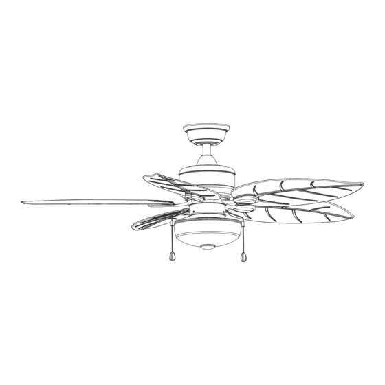
PALMARIA 52-INCH CEILING FAN
Questions, problems, missing parts? Before returning to the store,
call Hampton Bay Customer Service
8 a.m. - 7 p.m., EST, Monday-Friday, 9 a.m. - 6 p.m., EST, Saturday
1-855-HD-HAMPTON
HAMPTONBAY.COM
THANK YOU
We appreciate the trust and confidence you have placed in Hampton Bay through the purchase of this ceiling fan. We strive to continually create
quality products designed to enhance your home. Visit us online to see our full line of products available for your home improvement needs.
Thank you for choosing Hampton Bay!
Advertisement
Chapters
Table of Contents

Related Manuals for HAMPTON BAY PALMARIA EF200S(X)-52


Summary of Contents for HAMPTON BAY PALMARIA EF200S(X)-52
- Page 1 THANK YOU We appreciate the trust and confidence you have placed in Hampton Bay through the purchase of this ceiling fan. We strive to continually create quality products designed to enhance your home. Visit us online to see our full line of products available for your home improvement needs.
-
Page 2: Table Of Contents
Table of Contents Table of Contents ..............2 Assembly ................7 Safety Information ............... 2 Operation ................12 Warranty ................3 Care and Cleaning ............. 13 Pre-Installation ..............3 Troubleshooting ..............13 Installation ................6 Safety Information READ AND SAVE THESE INSTRUCTIONS. WARNING: To reduce the risk of personal injury, do not bend the blade brackets (also referred to as flanges) during assembly or after installation. -
Page 3: Warranty
A certain amount of “wobble” is normal and should not be considered a defect. Servicing performed by unauthorized persons shall render the warranty invalid. There is no other express warranty. Hampton Bay hereby disclaims any and all warranties, including but not limited to those of merchantability and fitness for a particular purpose to the extent permitted by law. - Page 4 Pre-Installation (continued) HARDWARE INCLUDED NOTE: Hardware not shown to actual size. Part Description Quantity Part Description Quantity Rubber gasket Plastic wire connector Pull chain Rubber plug Hanger pin Plastic plug Locking pin...
- Page 5 Pre-Installation (continued) PACKAGE CONTENTS Part Description Quantity Part Description Quantity Slide-on mounting bracket Fan-motor assembly (inside canopy) Light kit fitter assembly Ball/downrod assembly Blade Canopy Blade bracket Canopy ring (pre-assembled with canopy (C)) LED bulb Coupler cover IMPORTANT: This product and/or components are governed by one or more of the following U.S.
-
Page 6: Installation
Installation MOUNTING OPTIONS NOTE: You may need a longer downrod to maintain WARNING: To reduce the risk of fire, electric shock proper blade clearance when installing on a steep, sloped or personal injury, mount to outlet box marked ceiling. The maximum angle allowable is 30° away from “Acceptable for fan support of 35 lbs. - Page 7 Assembly - Standard Ceiling Mount Preparing for mounting Routing the wires □ □ Remove the canopy ring (D) from the canopy (C) by Route the wires exiting the top of the fan motor (F), through turning the ring counter-clockwise until it unlocks. the coupler cover (E) and canopy ring (D).
- Page 8 Assembly - Close to Ceiling Mount Preparing for mounting Routing the wires □ □ Remove the canopy ring (D) from the canopy (C) by turning the Remove three of the six screws and lock washers (every ring counter-clockwise until it unlocks. other one) securing the motor collar to the top of the fan □...
- Page 9 Assembly - Hanging the Fan Attaching the fan to the Hanging the fan electrical box □ Carefully lift the fan-motor assembly (F) up to the slide- WARNING: To reduce the risk of fire, electric shock or personal on mounting bracket (A). injury, mount to outlet box marked “Acceptable for fan support □...
-
Page 10: Assembly
Assembly - Hanging the Fan (continued) Making the electrical connection Wrapping the extra wire WARNING: Remove the rubber motor stops on the bottom of NOTE: Follow this step ONLY if you did not cut the extra length off the fan before installing the blades or testing the motor. from the wires coming from the ceiling fan. - Page 11 Assembly - Hanging the Fan (continued) Mounting the fan-motor assembly Standard mount (standard mount) WARNING: When using the standard ball/downrod mounting, the tab in the ring at the bottom of the mounting bracket must rest in the groove of the hanger ball. Failure to properly seat the tab in the groove could cause damage to the wiring.
- Page 12 Assembly - Attaching the Fan Blades Attaching the blades to blade brackets IMPORTANT: Insert the rubber plug (FF) to prevent water from entering the switch housing and to reduce the risk of fire, electric shock, or other personal injury. □ Remove and save the rubber plug (FF) from the switch cup to allow screw driver access when attaching blade arms.
- Page 13 Assembly - Attaching the Light Kit Attaching the light kit CAUTION: To reduce the risk of electric shock, disconnect the electrical supply circuit to the fan before installing the light kit. □ Remove the three screws (QQ) from the light kit fitter assembly (G).
- Page 14 Assembly - Assembling the Fan without the Light Kit Removing switch cup from glass bowl □ In order to use the fan without the light kit, remove the switch cup cover (GE) from the top of the light kit fitter assembly (G) by removing the center hex nut (GD) inside the switch cup cover, and then thread the switch cup cover off of the threaded nipple on the top of the light kit fitter assembly (G).
-
Page 15: Operation
Operation Turn on the power and check the operation of the fan. The pull Warm weather chain controls the fan speeds as follows: 1 pull - High, 2 pulls - Medium, 3 pulls - Low, 4 pulls - Off The appropriate speed settings for warm or cool weather depends on factors such as the room size, ceiling height, and number of fans. -
Page 16: Care And Cleaning
Care and Cleaning WARNING: Make sure the power is off before cleaning your fan. □ Because of the fan’s natural movement, some connections may become loose. Check the support connections, brackets, and blade attachments twice a year. Make sure they are secure. It is not necessary to remove the fan from the ceiling. □... - Page 17 Questions, problems, missing parts? Before returning to the store, call Hampton Bay Customer Service 8 a.m. - 7 p.m., EST, Monday-Friday, 9 a.m. - 6 p.m., EST, Saturday 1-855-HD-HAMPTON HAMPTONBAY.COM Retain this manual for future use.
- Page 18 GRACIAS Apreciamos la plena confianza que has depositado en Hampton Bay con la compra de este ventilador de techo. Nos esforzamos constantemente por crear productos de calidad diseñados para tu hogar. Visítanos por Internet para ver nuestra línea completa de productos disponibles a fin de...
- Page 19 Tabla de contenido Tabla de contenido .............. 2 Ensamblaje ................7 Información de seguridad........... 2 Operación ................12 Garantía ................3 Mantenimiento y limpieza ..........13 Preinstalación ..............3 Solución de problemas ............. 13 Instalación ................6 Información de seguridad ADVERTENCIA: Para reducir el riesgo de lesiones LEE Y GUARDA ESTAS INSTRUCCIONES.
-
Page 20: Garantía
Cualquier servicio prestado por personal no autorizado invalidará la garantía. No hay ninguna otra garantía expresa. Por este medio y en el alcance permitido por la ley, Hampton Bay queda exonerado de toda garantía, incluso, pero sin limitarse a ellas, aquellas de comercialización e idoneidad para un fin determinado. - Page 21 Preinstalación (continuación) HERRAJES INCLUIDOS NOTA: Los herrajes no se muestran en tamaño real. Pieza Descripción Cantidad Pieza Descripción Cantidad Junta de goma Conector plástico para cables Interruptor de cadena Tapón de goma Pasador de soporte Tapón plástico Pasador de cierre...
- Page 22 Preinstalación (continuación) CONTENIDO DEL PAQUETE Pieza Descripción Cantidad Pieza Descripción Cantidad Soporte de montaje deslizante Conjunto motor-ventilador (dentro de la cubierta) Conjunto ensamblado del soporte del Conjunto de tubo bajante/esfera kit de luces Cubierta Aspa Aro de la cubierta [preensamblado en la Soporte de aspa cubierta(C)] Bombilla LED...
-
Page 23: Instalación
Instalación OPCIONES DE MONTAJE ADVERTENCIA: Para reducir el riesgo de incendio, NOTA: Tal vez necesites un tubo bajante más largo para descarga eléctrica y lesiones, instala sólo en una caja mantener la altura mínima adecuada de las aspas al eléctrica clasificada como “apropiada para sostener instalar el ventilador en un techo inclinado. - Page 24 Ensamblaje - Montaje estándar en techo Preparación para el montaje Disposición de los cables □ □ Retira de la cubierta (C) su aro (D), girándolo hacia la Inserta los cables que salen por la parte superior del motor izquierda hasta liberarlo. del ventilador (F) a través de la cubierta del acoplador (E) y □...
- Page 25 Ensamblaje – Montaje cerca del cielo raso Preparación para el montaje Disposición de los cables □ □ Retira de la cubierta (C) su aro (D), girándolo hacia la izquierda Retira tres de los seis tornillos y arandelas de seguridad (en hasta liberarlo.
- Page 26 Ensamblaje - Cómo colgar el ventilador Cómo fijar el ventilador a Cómo colgar el ventilador la caja eléctrica □ Con cuidado, levanta el conjunto motor-ventilador (F) ADVERTENCIA: Para reducir el riesgo de incendio, descarga hasta el soporte de montaje deslizante (A). eléctrica y lesiones, instala sólo en una caja eléctrica □...
-
Page 27: Ensamblaje
Ensamblaje - Cómo colgar el ventilador (continuación) Cómo hacer las conexiones eléctricas Cómo enroscar el cable sobrante ADVERTENCIA: Quita los tapones de goma del motor en la parte inferior del ventilador antes de instalar las aspas o de NOTA: Siga este paso SOLO si no cortó el cable sobrante del verificar el motor. - Page 28 Ensamblaje - Cómo colgar el ventilador (continuación) Cómo montar el conjunto motor-ventilador Montaje estándar (montaje estándar) ADVERTENCIA: Cuando uses el conjunto del tubo bajante/esfera estándar, la pestaña en el aro en la parte inferior del soporte de montaje debe encajar en la ranura de la esfera de soporte. Si la pestaña no se asienta correctamente en la ranura, se puede dañar el cableado.
- Page 29 Ensamblaje - Cómo fijar las aspas del ventilador Cómo fijar las aspas a sus soportes IMPORTANTE: Inserta el tope de goma (FF) para evitar que entre agua a la caja del interruptor y reducir el riesgo de incendios, descargas eléctricas u otras lesiones físicas.
- Page 30 Ensamblaje - Cómo instalar el kit de luces Cómo instalar el kit de luces PRECAUCIÓN: Para disminuir el riesgo de descarga eléctrica, desconecta el circuito de energía del ventilador antes de instalar el kit de luces. □ Quita los tres tornillos (QQ) del conjunto del soporte del kit de luces (G).
- Page 31 Ensamblaje - Cómo ensamblar el ventilador sin el kit de luces Cómo quitar la caja del interruptor del tazón de vidrio □ Con el fin de utilizar el ventilador sin el kit de luces, retira la cubierta de la caja del interruptor (GE) de la parte superior del ensamblaje del soporte del kit de luces (G), retirando la tuerca hexagonal del centro (GD) dentro de la cubierta de la caja del interruptor;...
- Page 32 Funcionamiento Enciende la electricidad y comprueba el funcionamiento del Clima cálido ventilador. El interruptor de cadena controla las velocidades del ventilador de la siguiente manera: 1 vez: alta, 2 veces: media, 3 veces: baja y 4 veces: apagado. Las configuraciones de velocidadapropiadas para clima cálido o frío dependen de factores como tamaño de la habitación, altura del techo y cantidad de ventiladores.
-
Page 33: Mantenimiento Y Limpieza
Mantenimiento y limpieza ADVERTENCIA: Asegúrate de que la corriente esté apagada antes de limpiar el ventilador. □ Debido al movimiento natural del ventilador, algunas conexiones pueden aflojarse. Revisa dos veces al año las conexiones de soporte, los soportes y los accesorios de las aspas. Comprueba que estén seguros. No es necesario desmontar el ventilador del techo. □... - Page 34 ¿Preguntas, problemas, piezas faltantes? Antes de devolver a la tienda, llama al servicio al cliente de Hampton Bay entre 8 a.m. y 7 p.m. (Este), de lunes a viernes, o los sábados de 9 a.m. a 6 p.m. (Este). 1-855-HD-HAMPTON HAMPTONBAY.COM...
Need help?
Do you have a question about the PALMARIA EF200S(X)-52 and is the answer not in the manual?
Questions and answers