Table of Contents
Advertisement
Quick Links
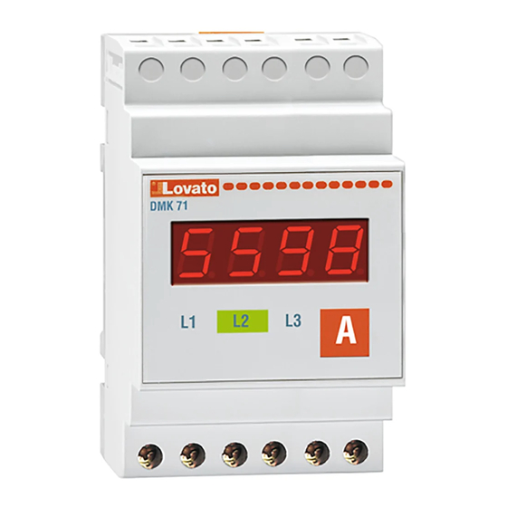
DMK71
DMK11
Schemat połączeń
Wiring diagram
DMK71
DMK11
Code: DMK71_DMK11-MH PL 100B0705
1/3
PL
AMPEROMIERZ CYFROWY
TRÓJFAZOWY
DMK71 / DMK11
UWAGA! Aby uniknąć zagrożenia dla zdrowia
i życia oraz uszkodzenia sprzętu, urządzenie powinno
być instalowane z zastosowaniem obowiązujących
norm przez wykwalifikowany personel. Przedstawiany
tu produkt może być w każdej chwili zmodyfikowany.
Dane techniczne oraz część opisowa oddają w jak najdokładniejszy
sposób posiadaną przez nas wiedzę, jednak nie bierzemy
odpowiedzialności za ewentualne błędy, braki oraz sytuacje
awaryjne. Instalacja urządzenia wymaga przełącznika load-break
albo automatycznego wyłącznika. Musi on być zainstalowany blisko
urządzenia, aby był łatwo dostępny dla operatora. Musi być
oznaczony jako niezależne urządzenie: IEC/EN 61010-§ 6.12.2.1.
Produkt musi być umieszczony w obudowie o stopniu ochrony
minimum IP40.
OPIS
Pomiar prądu (TRMS).
Zapamiętywanie wartości minimalnych i maksymalnych.
Ustawianie przekładni (CT) przyciskiem "A" .
WYŚWIETLANIE POMIARÓW
Wciśnij przycisk "A" by wyświetlić pomiary wskazane w poniższej tabeli:
LED
Pomiar
L1
Prąd fazy L1
L2
Prąd fazy L2
L3
Prąd fazy L3
Uwaga! Migająca dioda na wyświetlaczu oznacza pomiar wyrażony
w kA. Wskazanie "oL" oznacza przeciążenie wejścia pomiarowego.
WYŚWIETLANIE WARTOŚCI MIN I MAX ("HI" I "LO")
Wciśnij przycisk "A" przez 5 sekund do wyświetlenia "- - - - ".
Po 2 sek. pokaże się słowo "HI" i wartość maksymalna wybranego
pomiaru i następnie "LO" – wartość minimalna.
Wciśnij przycisk "A" by wybrać wartość "HI" i "LO" pozostałych
pomiarów.
Jeśli przycisk "A" jest wciśnięty przez kolejne 5 sek., wszystkie wartości
"Hi" i "Lo" są kasowane, to jest zapisują wartości obecnych pomiarów.
Wyświetla się słowo "CLr" (cleared) potwierdzające operację.
Jeśli przycisk "A", nie jest dłużej wciśnięty, po tym jak wartości "HI"
i "LO" zostały pokazane 3 razy, instrument przywraca wyświetlanie
normalnego pomiaru.
Uwaga: Wartości maksymalne pozostają w pamięci nawet kiedy DMK nie
jest zasilony.
USTAWIANIE PRZEKŁADNI CT
Wciśnij przycisk "A" przez 5 sekund do wyświetlenia " - - - - ",
następnie "puść" przycisk i natychmiast naciśnij go ponownie, przez 2
sek., aż do wyświetlenia P.01.
Z wyświetlonym "P01" wciśnij przycisk "A", by uzyskać dostęp do
ustawień przekładni CT.
Wciśnij przycisk "A" ponownie by wybrać prąd przekładni CT.
Wyświetlone wartości można przewijać przytrzymując wciśnięty
przycisk "A".
Jeśli wybrana została właściwa wartość przekładni i przycisk "A' nie jest
dłużej wciśnięty przez 2,5 sek, pojawia się P01.
Przy wyświetlonym P.01, instrument zapamiętuje wartości po 5 sek i
automatycznie wychodzi z ustawień. Podczas czasu wyświetlania P.01,
ustawienia mogą być zapamiętane przez wciśnięcie przycisku "A".
TABELA PARAMETRÓW
PAR
Funkcja
P.01
Prąd strony
pierwotnej
Uwaga: Wartość prądu strony pierwotnej 10000 jest wyświetlana jako
10.00, z migającą kropką, wskazującą kiloampery.
THREE-PHASE DIGITAL
AMMETER
DMK71 / DMK11
DESCRIPTION
Current measures in True RMS.
Storing of minimum and maximum values.
Current transformer (CT) primary setting using key "A"on front.
VIEWING OF MEASURES
Press the "A" key to view the measures indicated in the table below:
Notes! The flashing dot on the display indicates the measure is expressed
in kiloamperes. The "oL"indication means a measure input overload.
VIEWING OF MAXIMUM AND MINIMUM VALUES ("Hi" and "Lo")
Press the "A" key foat least 5 seconds untill "----" are shown.
After 2 seconds, the wording "HI" is viewed followed by the maximum
Press the "A" key to select the "Hi" and "Lo" values of the others
If the "A" key is maintained for another 5 seconds, all the "HI" and "LO"
Instead, if "A" key is not longer pushed, the instrument restores normal
Note: the maximum values remain stored in memory even when the DMK
CT SETTING
Press the "A" key for 5 seconds until " - - - - " are viewed, then release
With "P01" displayed, press the "A" key again to have access to the CT
Press the "A" key again to select the primary current of the CT. The
Once the required primary current value is displayed, P.01 is viewed if
At P.01 viewing, the instrument stores the value after 5 seconds and
Zakres
Domyślny
TABLE OF PARAMETERS
5 ÷ 10000A
5A
N.B. The value of the CT 10000° primary is viewed as 10.00, with flashing
dot, indicating kiloamperes.
06/02/2006
WARNING! This equipment is to be installed by qualified
personnel, complying to current standards, to avoid
damages or safety hazards. Products illustrated herein
are subject to alteration and changes without prior notice.
● Technical data and descriptions in the publication are accurate, to
the best of our knowledge, but no liabilities for errors, omissions or
contingencies arising therefrom are accepted.
● A load–break switch or circuit breaker must be included in the
electrical installation of the building. It must be installed close by the
equipment and within easy reach of the operator.
It must be marked as the disconnecting device of the equipment:
IEC /EN 61010-1 § 6.12.2.1
● Fit the instrument in an enclosure or cabinet with minimum IP40
degree protection.
LED
Measures
L1
Phase current of L1
L2
Phase current of L2
L3
Phase current of L3
value of the selected measure and then "LO" followed by the minimum
value.
measures.
values are cleared, that is they retain the same value of the measures
present in the moment. To confirm clearing, the wording "CLr" (cleared)
is displayed.
measures vieving after "HI" and "LO" values have been shown for 3
times.
is not powered
the key and immediately press it again, within 2 seconds, until "P.01" is
viewed.
setting.
displayed values rapidly scroll by keeping it pressed.
key "A" is not pressed for 2,5 seconds.
automatically exits the setting. During the P.01 viewing time, setting can
be restored by pressing the "A" key.
PAR
Function
Range
P.01
CT primary
5 ÷ 10000A
Default
5A
Str.
Advertisement
Table of Contents

Subscribe to Our Youtube Channel
Related Manuals for LOVATO ELECTRIC DMK71


Summary of Contents for LOVATO ELECTRIC DMK71
- Page 1 AMPEROMIERZ CYFROWY THREE-PHASE DIGITAL TRÓJFAZOWY AMMETER DMK71 / DMK11 DMK71 / DMK11 UWAGA! Aby uniknąć zagrożenia dla zdrowia WARNING! This equipment is to be installed by qualified i życia oraz uszkodzenia sprzętu, urządzenie powinno personnel, complying to current standards, to avoid być...
- Page 2 Typ zacisków Śrubowe DMK71/ wtykowe DMK11 Type of terminal Fixed / plug-in Przekrój przewodu 0.2 - 4.0 mm (24 - 12 AWG) – DMK71 Conductor cross 0.2 - 4.0 mm (24 - 12 AWG) (min i max) 0.2 - 2.5 mm (24 - 12 AWG) –...
- Page 3 Code: DMK71_DMK11-MH PL 100B0705 06/02/2006 Str.
Need help?
Do you have a question about the DMK71 and is the answer not in the manual?
Questions and answers