Table of Contents
Advertisement
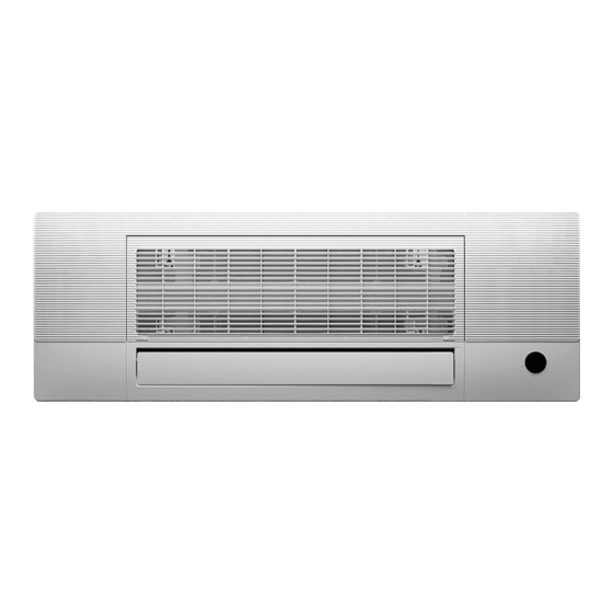
One Way Cassette Ductless Split Unit System - Sizes 06K - 18K
Fig. 1 - Sizes 06K - 18K
NOTE: Read the entire instruction manual before starting the
installation.
Images are for illustration purposes only. Actual models
may differ slightly.
DLFSOAH
Installation Instructions
SAFETY CONSIDERATIONS........................................................2
ACCESSORIES................................................................................3
PARTS..............................................................................................4
SYSTEM REQUIREMENTS...........................................................5
WIRING ...........................................................................................5
DIMENSIONS..................................................................................6
PRIOR TO INSTALLATION ..........................................................7
Step 1 - Select Unit Location............................................................7
Step 2 - Indoor Unit Installation .......................................................7
Step 3 - Optional Parts Installation...................................................9
ELECTRICAL DATA......................................................................10
CONNECTION DIAGRAMS ..........................................................10
WIRING DIAGRAM .......................................................................10
CAPACITY SETTING.....................................................................11
DRAIN PIPE INSTALLATION ......................................................12
REFRIGERANT PIPING CONNECTION......................................13
OPTIONAL PARTS INSTALLATION...........................................19
ELECTRICAL CONNECTIONS.....................................................20
TROUBLESHOOTING ...................................................................22
DUCTLESS START-UP CHECKLIST - Single Zone ....................23
Specifications subject to change without notice.
TABLE OF CONTENTS
PAGE
Advertisement
Table of Contents

Related Manuals for Carrier DLFSOAH


Summary of Contents for Carrier DLFSOAH
-
Page 1: Table Of Contents
DLFSOAH Installation Instructions One Way Cassette Ductless Split Unit System - Sizes 06K - 18K TABLE OF CONTENTS PAGE SAFETY CONSIDERATIONS............2 ACCESSORIES................3 PARTS....................4 SYSTEM REQUIREMENTS............5 WIRING ...................5 DIMENSIONS..................6 PRIOR TO INSTALLATION ............7 Step 1 - Select Unit Location............7 Fig. 1 — Sizes 06K - 18K Step 2 - Indoor Unit Installation ............7... -
Page 2: Safety Considerations
DLFSOAH: Installation Instructions SAFETY CONSIDERATIONS WARNING Improper installation, adjustment, alteration, service, maintenance, or use can cause explosion, fire, electrical shock, or other conditions which may cause death, personal injury or property damage. Consult a qualified ELECTRICAL SHOCK HAZARD installer, service agency, or your distributor or branch for information or Failure to follow this warning could result in personal injury or assistance. -
Page 3: Accessories
DLFSOAH: Installation Instructions ACCESSORIES The system is shipped with the following accessories (see Table 1). Use all of the installation parts and accessories to install the system. Improper installation may result in water leakage, electrical shock and fire, or cause the equipment to fail. -
Page 4: Parts
DLFSOAH: Installation Instructions PARTS Disconnect Switch (Factory Installed/Standard) Hanging bracket Outdoor unit power cable Fig. 2 — System Components NOTE: Illustrations in this manual are for reference only. The actual shape of the indoor unit and parts may differ slightly. -
Page 5: System Requirements
DLFSOAH: Installation Instructions SYSTEM REQUIREMENTS Allow sufficient space for airflow and unit service. See Fig. 3 — on page 6 for the minimum required distances between the unit and walls or ceilings. Table 4 — Indoor Unit Pipe Sizes UNIT SIZES... -
Page 6: Dimensions
DLFSOAH: Installation Instructions DIMENSIONS Installation place (unit: inch/mm) Wall Ceiling >7.87 in(200mm) air inlet air outlet Ceiling hole Indoor parts installation size (unit: inch/mm) 16.65in(423mm) 13.19in(335mm) 43.5in(1105mm) 53.54in(1360mm) Fig. 3 — Dimensions Manufacturer reserves the right to change, at any time, specifications and designs without notice and without obligations. -
Page 7: Prior To Installation
DLFSOAH: Installation Instructions PRIOR TO INSTALLATION Step 2 - Indoor Unit Installation Before installing the indoor unit, ensure the compatibility with the Ensure that only specified components are used for the installation. outdoor unit using the product data as a reference. It is also necessary to 1. - Page 8 DLFSOAH: Installation Instructions Connect the wire to the disconnect switch according to the Install the disconnect switch cover and secure the two screws. wire connecting diagram. Two screws Fig. 8 — Reinstall the cover TO INDOOR UNIT MAIN BOARD Disconnect...
-
Page 9: Step 3 - Optional Parts Installation
DLFSOAH: Installation Instructions Step 3 - Optional Parts Installation 3. Connect the other side of the connecting cable to the wire controller. Wire Controller For the function introduction, operation instruction and installation, refer to the wire controller installation and owner’s manual. However, for this unit, follow the steps for wire connection. -
Page 10: Electrical Data
DLFSOAH: Installation Instructions ELECTRICAL DATA Table 5 — Electrical Data ONE WAY CASSETTE (208/230V) (208/230V) (208/230V) (208/230V) Running Current Power Consumption Power Factor 64.4 64.4 97.7 67.7 CONNECTION DIAGRAMS Fig. 12 — Connection Diagram Sizes 06K-18K WIRING DIAGRAM TO WIRED... -
Page 11: Capacity Setting
DLFSOAH: Installation Instructions CAPACITY SETTING 18K to 12K Setting One-way cassette models are dual capacity and can be downsized by adjusting the dial switch ENC1 found in the main board as shown in The default capacity of DLFSOAH18XAK is 18K BTUH, to downsize it Figure 14. -
Page 12: Drain Pipe Installation
DLFSOAH: Installation Instructions DIP SWITCH SETTINGS Table 7 — Dip Switch Settings 1 OFF&2 DIAL CODE FUNCTION 1 ON&2 ON 1 ON&2 OFF 1 OFF&2 OFF Fan speed control after compressor [Default] SW2-1 Lowest speed stops Fan stop [Default] Breezeless... -
Page 13: Refrigerant Piping Connection
DLFSOAH: Installation Instructions Drill a Wall Hole REFRIGERANT PIPING CONNECTION When connecting the refrigerant piping, do not allow substances or 1. Use a 2.5in (65mm) or 3.5in (90mm) (depending on models) core drill to gases, other than the specified refrigerant, to enter the unit. The presence drill a hole in the wall. -
Page 14: Connection Instructions - Refrigerant Piping
DLFSOAH: Installation Instructions CONNECTION INSTRUCTIONS - Step 3 - Flare Pipe Ends REFRIGERANT PIPING Proper flaring is essential to achieve an airtight seal. 1. After removing burrs from the cut pipe, seal the ends with PVC tape to prevent foreign materials from entering the pipe. - Page 15 DLFSOAH: Installation Instructions Step 4 - Connect The Pipes Connect the copper pipes to the indoor unit first, then connect them to the outdoor unit. Connect the low pressure pipe then the high pressure pipe. CAUTION 1. When connecting the flare nuts, apply a thin coat of refrigeration oil to Be sure to wrap the insulation around the piping.
- Page 16 DLFSOAH: Installation Instructions Step 5 - Panel Installation - Ceiling Prep Use the following steps to prepare the ceiling. 3. Manually rotate the louver, secure the panel to the cassette with 3×M4*22 screws and a ST3.9*16 screw. 1. Drill a 16.93”x51.18” (430 mm x 1300 mm) hole into the ceiling based on the layout of the installation board.
- Page 17 DLFSOAH: Installation Instructions Model B NOTE: The corresponding colors or pins are connected to each other. 1. Press the circular position to open the two screw covers, then remove the two screws. (white 5-core) (white 10-core) ( 4 core) (red 5-core) Screw Covers Fig.
- Page 18 DLFSOAH: Installation Instructions 4. Manually rotate the louver, secure the panel to the cassette with 6. Connect the display board to the main control board, up to four wires 3×M4*22 screws and a ST3.9*16 screw. are required to make the connection.
-
Page 19: Optional Parts Installation
DLFSOAH: Installation Instructions OPTIONAL PARTS INSTALLATION Wi-Fi Dongle Installation 3. Open the front panel and insert the Wi-Fi dongle into the reserved interface. Use the following steps below to install the Wi-Fi dongle. NOTE: If you choose this configuration, it is recommended that the... -
Page 20: Electrical Connections
DLFSOAH: Installation Instructions ELECTRICAL CONNECTIONS NOTE: Before performing any electrical work, read these regulations. WARNING 1. All wiring must comply with local and national electrical codes, regulations, and must be installed by a licensed electrician Before performing any electrical or wiring work, turn off the main power to the system. - Page 21 DLFSOAH: Installation Instructions WIRELESS REMOTE CONTROL HOLDER OPTIONAL WIRED WALL-MOUNTED INSTALLATION REMOTE CONTROL INSTALLATION NOTE: For setup instructions, refer to the Wired Controller Installation Manual (KSACN0701AAA). SYSTEM CHECKS 1. Conceal the tubing where possible. 2. Ensure the drain tube slopes downward along its entire length.
-
Page 22: Troubleshooting
DLFSOAH: Installation Instructions TROUBLESHOOTING For ease of service, the systems are equipped with diagnostic code display LEDs on both the indoor and outdoor units. The indoor diagnostic display is a combination of flashing LEDs on the display panel or the front of the unit. -
Page 23: Ductless Start-Up Checklist - Single Zone
DLFSOAH: Installation Instructions DUCTLESS START-UP CHECKLIST - Single Zone Installation Data Site Address:_______________________________________________________________________________________________________ City:________________________________________________________ State:___________ Zip Code:__________________ Installing Contractor:______________________________________________________ Contractor Contact #: ( ) _____-___________ Job Name:_______________________________________________________________ Start-up Date:_____________________________ Distributor:_______________________________________________________________ System Details UNITS MODEL NO. SERIAL NO. CONTROLLER OUTDOOR UNIT... - Page 24 Outdoor Unit Error Code: Wall Controller: 24V Interface: Comments: __________________________________________________________________________________________________________________ __________________________________________________________________________________________________________________ © 2022 Carrier. All rights reserved. Edition Date: 12/22 Catalog No: IM-DLFSOAH-01 Replaces: NEW Manufacturer reserves the right to change, at any time, specifications and designs without notice and without obligations.
Need help?
Do you have a question about the DLFSOAH and is the answer not in the manual?
Questions and answers