Table of Contents
Advertisement
Quick Links
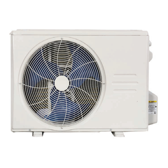
Outdoor Unit Single Zone Ductless System - Sizes 06K to 33K
Fig. 1 - Sizes 06K to 33K
NOTES: Read the entire instruction manual before
starting the installation.
Images are for illustration purposes only. Actual
models may differ slightly.
D5CSHAH
Installation Instructions
SAFETY CONSIDERATIONS........................................................2
ACCESSORIES................................................................................6
DIMENSIONS..................................................................................7
CLEARANCES ................................................................................12
INSTALLATION .............................................................................13
REFRIGERANT PIPING.................................................................14
EVACUATE COIL AND TUBING SYSTEM................................17
WIRING ...........................................................................................18
ELECTRICAL DATA......................................................................18
INSTALL THE OUTDOOR UNIT..................................................19
Step 1 - Select the Installation Location ...........................................19
Step 2 - Install the Drain Joint ..........................................................20
Step 3 - Anchor the Outdoor Unit.....................................................21
Step 4 - Connect Signal and Power Cables ......................................22
START-UP .......................................................................................24
CARE AND MAINTENANCE........................................................24
TROUBLESHOOTING ...................................................................24
ERROR CODES...............................................................................25
DUCTLESS START-UP CHECKLIST - Single Zone ....................26
Specifications subject to change without notice.
TABLE OF CONTENTS
PAGE
Advertisement
Table of Contents

Subscribe to Our Youtube Channel
Related Manuals for Carrier D5CSHAH


Summary of Contents for Carrier D5CSHAH
-
Page 1: Table Of Contents
D5CSHAH Installation Instructions Outdoor Unit Single Zone Ductless System - Sizes 06K to 33K TABLE OF CONTENTS PAGE SAFETY CONSIDERATIONS............2 ACCESSORIES................6 DIMENSIONS..................7 CLEARANCES ................12 INSTALLATION ................13 REFRIGERANT PIPING..............14 EVACUATE COIL AND TUBING SYSTEM........17 WIRING ...................18 ELECTRICAL DATA..............18 INSTALL THE OUTDOOR UNIT..........19 Step 1 - Select the Installation Location ...........19... -
Page 2: Safety Considerations
D5CSHA: Installation Instructions SAFETY CONSIDERATIONS Installing, starting up, and servicing air- conditioning equipment can be Refrigerant hazardous due to system pressures, electrical components, and equipment R-454B R-454B Safety Group location (roofs, elevated structures, etc.). Only trained, qualified installers and service mechanics should install, start- up, and service this equipment. - Page 3 D5CSHA: Installation Instructions Mechanical Code, or CSA B52. All field joints shall be accessible for inspection prior to being covered or enclosed. CAUTION - that protection devices, piping, and fittings shall be protected as far as possible against adverse environmental effects, for example, the danger of water collecting and freezing in relief pipes or the EQUIPMENT DAMAGE HAZARD accumulation of dirt and debris;...
- Page 4 D5CSHA: Installation Instructions 6. Detection of Flammable Refrigerants Under no circumstances shall potential sources of ignition be used in For appliances containing flammable refrigerants, refrigerants the searching for or detection of refrigerant leaks. A halide torch (or purging shall be achieved by breaking the vacuum in the system with any other detector using a naked flame) shall not be used.
- Page 5 D5CSHA: Installation Instructions Table 1 — A (min) hinst: Height Above Floor Level to Center of Indoor Unit / feet (meters ≤ 7.2 (2.2) 7.5 (2.3) 7.9 (2.4) 8.5 (2.6) 9.2 (2.8) 9.8 (3.0) ≤ 3.91 (1.776) 12 (1.10) 4.0 (1.8) 60 (5.53) 57 (5.29) 55 (5.07)
-
Page 6: Accessories
D5CSHA: Installation Instructions ACCESSORIES The system is shipped with the following accessories. Use all of the installation parts and accessories to install the system. Improper installation may result in water leakage, electrical shock and fire, or cause the equipment to fail. Keep the installation manual in a safe place and do not discard any other accessories until the installation work has been completed. -
Page 7: Dimensions
D5CSHA: Installation Instructions DIMENSIONS Table 3 — Dimensions and Weights SYSTEM SIZE (208/230 V) (208/230 V) (208/230V) (208/230 V) (208/230 V) (208/230 V) Height (H) in (mm) 21.85 (555) 21.81 (554) 21.81 (554) 26.50 (673) 31.89 (810) 31.89 (810) Width (W) in (mm) 30.12 (765) 31.69 (805) - Page 8 D5CSHA: Installation Instructions Fig. 3 — Size 06K Manufacturer reserves the right to change, at any time, specifications and designs without notice and without obligations.
- Page 9 D5CSHA: Installation Instructions Fig. 4 — Sizes 09K - 12K Manufacturer reserves the right to change, at any time, specifications and designs without notice and without obligations.
- Page 10 D5CSHA: Installation Instructions Fig. 5 — Size 18K Manufacturer reserves the right to change, at any time, specifications and designs without notice and without obligations.
- Page 11 D5CSHA: Installation Instructions Fig. 6 — Sizes 24K and 33K Manufacturer reserves the right to change, at any time, specifications and designs without notice and without obligations.
-
Page 12: Clearances
D5CSHA: Installation Instructions CLEARANCES Air inlet Air outlet Fig. 7 — Clearances Table 4 — Clearance Dimensions MINIMUM VALUE UNIT IN. (MM) 24 (610) 24 (610) 24 (610) 4 (101) 4 (101) NOTE: The outdoor unit must be mounted at least 2in (50mm) above the maximum anticipated snow depth. 19in (48cm) or more on a multiple parallel unit arrangement 4in (10cm) -
Page 13: Installation
D5CSHA: Installation Instructions INSTALLATION IMPORTANT: Both refrigerant lines must be insulated separately. Use refrigeration grade tubing ONLY. No other • A location which is convenient to installation and not exposed to type of tubing may be used. Use of other types of tubing will strong winds. -
Page 14: Refrigerant Piping
D5CSHA: Installation Instructions REFRIGERANT PIPING Table 6 — Refrigerant Piping Table MODEL D5CSHAQ06AA3 D5CSHAQ09AA3 D5CSHAQ12AA3 D5CSHAQ18AA3 D5CSHAQ24AA3 D5CSHAQ33AA3 Refrigerant Type Type R454B R454B R454B R454B R454B R454B Charge Amount lb. (kg) 2.03 (0.92) 2.2 (1.00) 2.2 (1.00) 3.46 (1.57) 3.97 (1.80) 5.45 (2.47) Additional refrigerant Oz/ft (g/m) - Page 15 D5CSHA: Installation Instructions Use the following steps to connect the refrigerant piping: 5. Flare Pipe Ends Proper flaring is essential to achieving an airtight seal. 1. Run the interconnecting piping from the outdoor unit to the indoor unit. a. After removing the burrs from the cut pipe, seal the ends with PVC 2.
- Page 16 D5CSHA: Installation Instructions 6. Connect the Pipes Connect the copper pipes to the indoor unit first, then connect the e. After connecting the copper pipes to the indoor unit, wrap the pipes to the outdoor unit. Connect the low-pressure pipe first, then power cable, signal cable and the piping together with binding connect the high pressure pipe.
-
Page 17: Evacuate Coil And Tubing System
D5CSHA: Installation Instructions EVACUATE COIL AND TUBING SYSTEM Evacuation Evacuation of the system removes air or nitrogen (non-condensables) as well CAUTION as moisture. A proper vacuum assures a tight, dry system before charging with refrigerant. The two methods used to evacuate a system are the deep vacuum method and the triple vacuum method. -
Page 18: Wiring
D5CSHA: Installation Instructions WIRING CAUTION All wires must be sized per NEC (National Electrical Code) or CEC (Canadian Electrical Code) and local codes. Use Electrical Data table MCA EQUIPMENT DAMAGE HAZARD (minimum circuit amps) and MOCP (maximum over current protection) to Failure to follow this caution may result in equipment damage or correctly size the wires and the disconnect fuse or breakers respectively. -
Page 19: Install The Outdoor Unit
D5CSHA: Installation Instructions INSTALL THE OUTDOOR UNIT Step 1 - Select the Installation Location NOTE: Before installing the outdoor unit, select an appropriate location. The following details are standards designed to help select an appropriate location for the unit. Proper installation locations meet the following standards: 20in.(500mm) or more when front and sides of the unit are clear Noise from the unit... -
Page 20: Step 2 - Install The Drain Joint
D5CSHA: Installation Instructions Step 2 - Install the Drain Joint NOTE: Before bolting the outdoor unit in place, you must install the drain joint at the bottom of the unit. For units with a base pan built-in (with multiple holes for proper draining during defrost), the drain joint is not needed to be installed. 1. -
Page 21: Step 3 - Anchor The Outdoor Unit
D5CSHA: Installation Instructions Step 3 - Anchor the Outdoor Unit WARNING When drilling into concrete, eye protection is recommended at all times. • The outdoor unit can be anchored to the ground or to a wall-mounted bracket with bolt (M10). Prepare the installation base of the unit according to Figure 22. -
Page 22: Step 4 - Connect Signal And Power Cables
D5CSHA: Installation Instructions Step 4 - Connect Signal and Power Cables WARNING All wiring work must be performed strictly in accordance with the wiring diagram located in the wire cover of the outdoor unit. Before performing any electrical or wiring work, turn off the main power to the system. - Page 23 D5CSHA: Installation Instructions The outside unit’s terminal block is protected by an electrical wiring cover on the side of the unit. A comprehensive wiring diagram is printed on the inside of the wiring cover. Terminal block 1. Remove the wire cover from the unit by loosening the 3 screws. 2.
-
Page 24: Start-Up
D5CSHA: Installation Instructions START-UP CARE AND MAINTENANCE Test Operation To help ensure high performance and minimize possible equipment failure, periodic maintenance must be performed on this equipment. Perform a test operation after completing a gas leak and electrical safety Maintenance frequency may vary depending upon geographic areas. check. -
Page 25: Error Codes
D5CSHA: Installation Instructions ERROR CODES Table 12 — Error Codes Display Malfunction and Protection Indication Display Malfunction and Protection Indication Other indoor unit refrigerant sensor detects a leak (multi-zone) ODL Current Protection ECC1 PC08 Outdoor DC fan motor speed out of control ODL AC voltage too low protection EC07 PC10... -
Page 26: Ductless Start-Up Checklist - Single Zone
D5CSHA: Installation Instructions DUCTLESS START-UP CHECKLIST - Single Zone Installation Data Site Address:_______________________________________________________________________________________________________ City:________________________________________________________ State:___________ Zip Code:__________________ Installing Contractor:______________________________________________________ Contractor Contact #: ( ) _____-___________ Job Name:_______________________________________________________________ Start-up Date:_____________________________ Distributor:_______________________________________________________________ System Details UNITS MODEL NO. SERIAL NO. CONTROLLER OUTDOOR UNIT INDOOR UNIT A Are the outdoor unit and indoor unit compatible? YES:______ NO:______... -
Page 27: Performance Check
D5CSHA: Installation Instructions Ductless Start-Up Checklist (CONT) Piping Leak Check: System held 500 psig (max. 550psi) for a minimum of 30 minutes using dry nitrogen. YES:______ NO:______ Evacuation Method: • YES:______ NO:______ Was the Triple Evacuation Method used as outlined in the installation manual? •... - Page 28 D5CSHA: Installation Instructions © 2024 Carrier. All rights reserved. Edition Date: 07/24 Catalog No: D5CSHAH-01SI A Carrier company Replaces: NEW Manufacturer reserves the right to change, at any time, specifications and designs without notice and without obligations.
Need help?
Do you have a question about the D5CSHAH and is the answer not in the manual?
Questions and answers