Table of Contents
Advertisement
Available languages
Available languages
Quick Links
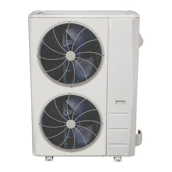
Outdoor Unit Single Zone Ductless System - Sizes 36 to 58
Fig. 1 —Size 36K
Fig. 2 —Sizes 48K - 58K
NOTES: Read the entire instruction manual before
starting the installation.
Images are for illustration purposes only. Actual
models may differ slightly.
DLCLRC
Installation Instructions
SAFETY CONSIDERATIONS . . . . . . . . . . . . . . . . . . . . . . . . . . . . . 2
INTRODUCTION . . . . . . . . . . . . . . . . . . . . . . . . . . . . . . . . . . . . . . . 3
ACCESSORIES . . . . . . . . . . . . . . . . . . . . . . . . . . . . . . . . . . . . . . . . . 3
DIMENSIONS . . . . . . . . . . . . . . . . . . . . . . . . . . . . . . . . . . . . . . . . . . 4
CLEARANCES . . . . . . . . . . . . . . . . . . . . . . . . . . . . . . . . . . . . . . . . . 6
INSTALLATION REQUIREMENTS . . . . . . . . . . . . . . . . . . . . . . . . 7
INSTALLATION . . . . . . . . . . . . . . . . . . . . . . . . . . . . . . . . . . . . . . . . 7
Step 1 - Check Equipment . . . . . . . . . . . . . . . . . . . . . . . . . . . . . . . . . 7
Step 2 - Mount Unit . . . . . . . . . . . . . . . . . . . . . . . . . . . . . . . . . . . . . . 7
Step 3 - Condensate Drain Installation . . . . . . . . . . . . . . . . . . . . . . . . 8
Step 4 - Refrigerant Piping . . . . . . . . . . . . . . . . . . . . . . . . . . . . . . . . . 9
Step 5 - Evacuate Coil And Tubing System . . . . . . . . . . . . . . . . . . . 12
Step 6 - Electrical Connections. . . . . . . . . . . . . . . . . . . . . . . . . . . . . 13
WIRING . . . . . . . . . . . . . . . . . . . . . . . . . . . . . . . . . . . . . . . . . . . . . . 13
ELECTRICAL DATA . . . . . . . . . . . . . . . . . . . . . . . . . . . . . . . . . . . 14
CONNECTION DIAGRAMS . . . . . . . . . . . . . . . . . . . . . . . . . . . . . 14
START-UP . . . . . . . . . . . . . . . . . . . . . . . . . . . . . . . . . . . . . . . . . . . . 15
CARE AND MAINTENANCE . . . . . . . . . . . . . . . . . . . . . . . . . . . . 15
OUTDOOR UNIT DIAGNOSTIC GUIDES . . . . . . . . . . . . . . . . . . 15
DUCTLESS START-UP CHECKLIST . . . . . . . . . . . . . . . . . . . . . . 16
Specifications subject to change without notice.
TABLE OF CONTENTS
Page
Advertisement
Table of Contents

Related Manuals for Carrier DLCLRC


Summary of Contents for Carrier DLCLRC
- Page 1 DLCLRC Installation Instructions Outdoor Unit Single Zone Ductless System - Sizes 36 to 58 TABLE OF CONTENTS Page SAFETY CONSIDERATIONS ......2 INTRODUCTION .
-
Page 2: Safety Considerations
DLCLRC: Installation Instructions SAFETY CONSIDERATIONS WARNING Installing, starting up, and servicing air- conditioning equipment can be hazardous due to system pressures, electrical components, and equipment location (roofs, elevated structures, etc.). ELECTRICAL SHOCK HAZARD Only trained, qualified installers and service mechanics should install, Failure to follow this warning could result in personal injury or start- up, and service this equipment. - Page 3 DLCLRC: Installation Instructions INTRODUCTION The Horizontal Discharge Outdoor units are R-410A condensing units designed with application flexibility in mind. These units have a max total piping length up to 213 ft (65 m) and a maximum piping lift of up to 98 ft (30m).
- Page 4 DLCLRC: Installation Instructions DIMENSIONS Table 3 — Dimensions UNIT SIZE Height in (mm) 31.89 (810) 52.48 (1333) 52.48 (1333) Width in (mm) 37.24 (946) 37.48 (952) 37.48 (952) Depth in (mm) 16.14 (410) 16.34 (415) 16.34 (415) Operating Weight lbs (kg) 155.42 (70.5)
- Page 5 DLCLRC: Installation Instructions DIMENSIONS (CONT.) Sizes 48K - 58K Fig. 5 —Sizes 48K - 58K Manufacturer reserves the right to change, at any time, specifications and designs without notice and without obligations.
-
Page 6: Air Inlet
DLCLRC: Installation Instructions CLEARANCES Air inlet Air outlet Fig. 6 — Outdoor Unit Clearances Table 4 — Outdoor Unit Clearance Dimensions MINIMUM VALUE UNIT in. (mm) 24 (610) 24 (610) 24 (610) 4 (101) 4 (101) 19in (48cm) or more on... -
Page 7: Installation Requirements
DLCLRC: Installation Instructions INSTALLATION REQUIREMENTS INSTALLATION • A location which is convenient to installation and not exposed to strong Step 1 - Check Equipment winds. Unpack the unit and move to the final location. Remove the carton, taking • A location which can bear the weight of the outdoor unit and where the care not to damage the unit. -
Page 8: Step 3 - Condensate Drain Installation
DLCLRC: Installation Instructions Step 3 - Condensate Drain Installation CAUTION Install drains must meet local sanitation codes. Install the outdoor unit drain joint EQUIPMENT DAMAGE HAZARD Fit the seal into the drain joint, then insert the drain joint into the base pan In cold climates, ensure the drain hose is as vertical as possible to hole of the outdoor unit. -
Page 9: Step 4 - Refrigerant Piping
DLCLRC: Installation Instructions Step 4 - Refrigerant Piping Table 6 — Piping and Refrigerant Information SYSTEM SIZE Min. Piping Length ft (m) 10(3) 10(3) 9.8 (3) Standard Piping Length ft (m) 25(7.5) 25(7.5) 24.6 (7.5) Max. outdoor-indoor height difference (OU higher than IU) - Page 10 DLCLRC: Installation Instructions Use the following steps to connect the refrigerant piping: 5. Flare Pipe Ends 1. Run the interconnecting piping from the outdoor unit to the indoor Proper flaring is essential to achieving an airtight seal. unit. a. After removing the burrs from the cut pipe, seal the ends with PVC 2.
- Page 11 DLCLRC: Installation Instructions 6. Connect the Pipes Connect the copper pipes to the indoor unit first, then connect the All tubing bends should be performed with a properly sized tubing bender pipes to the outdoor unit. Connect the low-pressure pipe first, then to prevent kinking or damaging the tubing.
- Page 12 DLCLRC: Installation Instructions Step 5 - Evacuate Coil And Tubing System Evacuation Evacuation of the system will remove air or nitrogen (non-condensables) as CAUTION well as moisture. A proper vacuum will assure a tight, dry system before charging with refrigerant. The two methods used to evacuate a system are the deep vacuum method and the triple vacuum method.
- Page 13 DLCLRC: Installation Instructions Step 6 - Electrical Connections WIRING Install All Power and Interconnecting Wiring to All wires must be sized per NEC (National Electrical Code) or CEC (Canadian Electrical Code) and local codes. Use Electrical Data table MCA (minimum...
-
Page 14: Electrical Data
DLCLRC: Installation Instructions ELECTRICAL DATA Table 9 — Electrical Data OUTDOOR UNIT SIZE 208/230 - 1 - 60 208/230 - 1 - 60 208/230 - 1 - 60 Max – Min* Oper. Voltage 253 - 187 253 - 187 253 - 187... -
Page 15: Care And Maintenance
DLCLRC: Installation Instructions START-UP Outdoor Unit Are there unusual noises or vibrations during operation? Test Operation Explain the Following Item to the Customer (with the aid of Perform a test operation after completing a gas leak and electrical safety the Owner's Manual): check. -
Page 16: Installation Data
DLCLRC: Installation Instructions DUCTLESS START-UP CHECKLIST Installation Data Site Address:_______________________________________________________________________________________________________ City:________________________________________________________ State:___________ Zip Code:__________________ Installing Contractor:______________________________________________________ Contractor Contact #: ( ) _____-___________ Job Name:_______________________________________________________________ Start-up Date:_____________________________ Distributor:_______________________________________________________________ System Details Units Model No. Serial No. Controller OUTDOOR UNIT INDOOR UNIT A... -
Page 17: Performance Check
DLCLRC: Installation Instructions Ductless Start-Up Checklist (CONT) Piping Leak Check: System held 500 psig (max. 550psi) for a minimum of 30 minutes using dry nitrogen. YES:______ NO:______ Evacuation Method: • YES:______ NO:______ Was the Triple Evacuation Method used as outlined in the installation manual? •... - Page 18 DLCLRC: Installation Instructions © 2022 Carrier. All rights reserved. Edition Date: 04/22 Catalog No: DLCLRC-01SI Replaces: NEW Manufacturer reserves the right to change, at any time, specifications and designs without notice and without obligations.
-
Page 19: Table Of Contents
DLCLRC Instructions d’installation Appareil extérieur monozone sans conduit - Capacités 36 à 58 TABLE DES MATIÈRES Page CONSIDÉRATIONS DE SÉCURITÉ ......2 INTRODUCTION . -
Page 20: Considérations De Sécurité
DLCLRC: Instructions d’installation CONSIDÉRATIONS DE SÉCURITÉ AVERTISSEMENT L’installation, le démarrage et l’entretien des équipements de climatisation peuvent être dangereux à cause des pressions présentes dans le système, des composants électriques et de RISQUE D’ÉLECTROCUTION l’emplacement des équipements (toits, structures surélevées, etc.). -
Page 21: Introduction
DLCLRC: Instructions d’installation INTRODUCTION Les appareils extérieurs à soufflage horizontal sont des groupes compresseur-condenseur R-410A conçus pour offrir une flexibilité d’utilisation. Ces appareils ont une longueur de tuyauterie maximale de 65 pi (213 m), avec une élévation maximale de 98 pi (30 m). -
Page 22: Dimensions
DLCLRC: Instructions d’installation DIMENSIONS Table 3 — Dimensions CAPACITÉ DE L’APPAREIL Hauteur po (mm) 31,89 (810) 52,48 (1 333) 52,48 (1 333) Largeur po (mm) 37,24 (946) 37,48 (952) 37,48 (952) Profondeur po (mm) 16,14 (410) 16,34 (415) 16,34 (415) Poids opérationnel... - Page 23 DLCLRC: Instructions d’installation DIMENSIONS (SUITE) Capacités 48K - 58K Fig. 5 —Capacités 48K - 58K Le fabricant se réserve le droit de changer les spécifications ou la conception sans avis préalable et sans obligation de sa part.
-
Page 24: Dégagements
DLCLRC: Instructions d’installation DÉGAGEMENTS Entrée d’air Sortie d’air Fig. 6 — Dégagement de l’appareil extérieur Table 4 — Dimensions – Dégagement de l’appareil extérieur VALEUR MINIMALE po (mm) 24 (610) 24 (610) 24 (610) 4 (101) 4 (101) 19 po (48 cm) ou plus pour une disposition de modules multiples en parallèle 4 po (10 cm) ou plus... -
Page 25: Recommandations D'installation
DLCLRC: Instructions d’installation RECOMMANDATIONS INSTALLATION D’INSTALLATION Étape 1 − Vérification de l’équipement • Emplacement pratique pour l’installation et non exposé à de forts Déballez l’appareil et placez-le à son emplacement final. Enlevez vents. l’emballage, en prenant soin de ne pas endommager l’appareil. Inspectez •... -
Page 26: Étape 3 − Installation De L'évacuation De Condensat
DLCLRC: Instructions d’installation Étape 3 − Installation de l’évacuation de MISE EN GARDE condensat Installez les flexibles d’évacuation conformément aux codes sanitaires locaux. RISQUE DE DÉTÉRIORATION DES ÉQUIPEMENTS Dans les climats froids, vérifiez que le flexible d’évacuation est Installation du raccord d’évacuation installé... -
Page 27: Étape 4 − Tuyauterie De Frigorigène
DLCLRC: Instructions d’installation Étape 4 − Tuyauterie de frigorigène Table 6 — Renseignements au sujet de la tuyauterie et du frigorigène CAPACITÉ DU SYSTÈME Longueur minimale de la tuyauterie m (pi) 10 (3) 10 (3) 9.8 (3) Longueur standard de la tuyauterie... - Page 28 DLCLRC: Instructions d’installation Pour raccorder le tuyau de frigorigène, réalisez les étapes suivantes : 5. Évasement de l’extrémité du tuyau 1. Acheminez la tuyauterie d’interconnexion entre l’appareil extérieur Un bon évasement est essentiel pour obtenir un joint étanche. et l’appareil intérieur.
- Page 29 DLCLRC: Instructions d’installation 6. Raccordez les tuyaux f. Après avoir connecté le tuyau en cuivre au module intérieur, enroulez le câble d’alimentation, le câble de signal et la Raccordez d’abord les tuyaux en cuivre au module intérieur, puis tuyauterie ensemble avec du ruban d’assemblage.
-
Page 30: Étape 5 - Évacuation Du Serpentin Et Du Système De Tuyauterie
DLCLRC: Instructions d’installation Étape 5 – Évacuation du serpentin et du Évacuation L’évacuation du système élimine l’air ou l’azote (non condensables) ainsi que système de tuyauterie l’humidité. Un bon aspirateur assure un système étanche et sec avant de charger le frigorigène. Deux méthodes sont utilisées pour évacuer un MISE EN GARDE système : méthode de vide profond et méthode d’évacuation triple. -
Page 31: Étape 6 - Branchements Électriques
DLCLRC: Instructions d’installation Étape 6 – Branchements électriques CIRCUIT DE TERRE La dimension de tous les fils doit être conforme aux exigences du NEC Installez tout le câblage électrique et d’interconnexion (National Electrical Code) ou au CEC (Code électrique canadien) et aux codes des appareils extérieurs. -
Page 32: Données Électriques
DLCLRC: Instructions d’installation DONNÉES ÉLECTRIQUES Table 10 — Données électriques CAPACITÉ DE L’APPAREIL EXTÉRIEUR 208/230 – 1 – 60 208/230 – 1 – 60 208/230 – 1 – 60 Tension de fonctionnement 253 – 187 253 – 187 253 – 187 max –... -
Page 33: Mise En Service
DLCLRC: Instructions d’installation MISE EN SERVICE Essai de fonctionnement Effectuez un essai de fonctionnement après avoir terminé la recherche de fuite de gaz et la vérification de sécurité électrique. Consultez les instructions d’installation du module intérieur et le manuel du propriétaire pour obtenir des renseignements supplémentaires sur la mise en service. -
Page 34: Guides De Diagnostic De L'appareil Extérieur
DLCLRC: Instructions d’installation GUIDES DE DIAGNOSTIC DE L’APPAREIL EXTÉRIEUR Pour faciliter l’entretien, les systèmes sont équipés de DEL d’affichage de codes de diagnostic sur le module intérieur et l’appareil extérieur. Le diagnostic de l’appareil extérieur s’affiche sur la carte du microprocesseur de l’appareil extérieur. -
Page 35: Liste De Vérification De Mise En Service
DLCLRC: Instructions d’installation LISTE DE VÉRIFICATION DE MISE EN SERVICE Données d’installation Adresse du site : ____________________________________________________________________________________________________ Ville :________________________________________________________État :___________Code postal :_______________ Entrepreneur installateur :__________________________________________ Coordonnées de l’entrepreneur : ( ) _____-___________ Nom du poste : __________________________________________________________ Date de début : _____________________________ Distributeur : ___________________________________________________________ Détails du système... - Page 36 Interface 24 V : Commentaires : __________________________________________________________________________________________________________________ __________________________________________________________________________________________________________________ __________________________________________________________________________________________________________________ © 2022 Carrier. All rights reserved. Edition Date: 04/22 Catalog No: DLCLRC-01SIFR Replaces: NEW Manufacturer reserves the right to change, at any time, specifications and designs without notice and without obligations.
Need help?
Do you have a question about the DLCLRC and is the answer not in the manual?
Questions and answers