
Related Manuals for Gamry Instruments eQCM 15M

Summary of Contents for Gamry Instruments eQCM 15M
- Page 1 15M™ Electrochemical Quartz Crystal Microbalance Operator’s Manual Copyright 2023 Gamry Instruments, Inc. Revision 1.1 August 1, 2023 988-00089...
-
Page 3: If You Have Problems
Please have your instrument model and serial numbers available, as well as any applicable software and firmware revisions. If you have problems with installation or use of a system containing an eQCM 15M, please call from a phone next to your computer, where you can type and read the screen while talking to us. -
Page 4: Disclaimers
Disclaimers Disclaimers Gamry Instruments, Inc. cannot guarantee that the eQCM 15M will work with all computer systems, operating systems, or third-party hardware/software. The information in this manual has been carefully checked and is believed to be accurate as of the time of printing. -
Page 5: Table Of Contents
Table of Contents ............................5 Chapter 1: Safety Considerations ........................7 Inspection ............................... 7 Product Safety ............................7 Grounding in the eQCM 15M ......................... 7 Temperature and Ventilation ........................8 Defects and Abnormal Stresses ........................ 8 Environmental Limits ..........................9 Cleaning .............................. - Page 6 Table of Contents Frequency Characteristics ........................33 General ..............................33 Environmental ............................33 Appendix B: Certifications..........................35 Declaration of Conformity: No. DOC-2023-CE-eQCM15M ..............35 Certificate of Conformance ........................36 Declaration of Conformity: No. DOC-2023-UKCA-eQCM15M ............. 37 Appendix C: Comprehensive Index ....................... 39...
-
Page 7: Chapter 1: Safety Considerations
Grounding in the eQCM 15M A Chassis Ground binding post on the rear panel of the eQCM 15M is provided for a connection to earth ground. Simply run a wire from this binding post to a suitable source of earth ground. A black 1.2-m wire is... -
Page 8: Temperature And Ventilation
Note that this connection of the instrument to an earth ground is not a “Protective Earth Ground” as defined in EN 61010. This binding post is not intended for any use other than connecting the eQCM 15M to an earth ground to improve shielding against noise. Connecting this binding post to a hazardous voltage can create a significant safety hazard. -
Page 9: Environmental Limits
Safety Considerations Do not use your eQCM 15M or any other apparatus if you think it could be hazardous. Have it checked by qualified service personnel. Environmental Limits There are environmental-limit conditions on the storage, shipping, and operation of this equipment. The eQCM 15M is not designed for outdoor use. -
Page 10: Electrical Transient Sensitivity
USB supply and Electrostatic Discharge. The eQCM 15M is not rated for continuous use when subject to ESD events. It should suffer no permanent damage when subject to the standard ESD events defined in EN61000-4-2 but may cease normal operation until it is switched off and restarted. -
Page 11: Chapter 2: Introduction
Chapter 1 includes an in-depth discussion of safety issues. This chapter describes this manual and gives a brief overview of the eQCM 15M features. Chapter 3 is a description of the electronic circuitry in the eQCM 15M. Chapter 4 contains installation instructions. Chapter 5 describes inserting a crystal into a holder and connecting the holder to the eQCM 15M, and Chapter 6 describes the eQCM 15M’s front and rear panels. -
Page 13: Chapter 3: Instrument Circuitry
Instrument Circuitry Chapter 3: Instrument Circuitry eQCM 15M Schematic/Block Diagram If you are not familiar with electronic schematics or quartz crystal microbalances, you probably want to skip this chapter. This information is for expert use only and is not required for routine use of the instrument. -
Page 15: Chapter 4: Installation
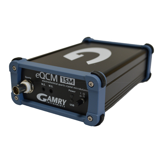
Front View of an eQCM 15M Initial Visual Inspection After you remove your eQCM 15M from its shipping carton, check it for any signs of shipping damage. If you find any damage, please notify Gamry Instruments, Inc., and the shipping carrier immediately. Save the shipping container for possible inspection by the carrier. -
Page 16: Computer Requirements
The eQCM 15M is completely compatible with the Windows Plug & Play configuration system. Like most Plug & Play hardware, it is best if you install the software for the eQCM 15M before you install the hardware. The latest Gamry software is not provided on a DVD anymore but is now available for download as *.exe or *.iso file on Gamry Instruments' Client Portal after creating an account and registering your instrument:... -
Page 17: Power-Up Test
Before you make any other connections to your eQCM 15M, check that the instrument is at least nominally functional. One quick test is to turn on the eQCM 15M and watch the blue Power LED indicator on the front panel. After connecting DC power to the instrument, turn press the Power button. -
Page 18: First-Time Device Installation In Windows
If the Power LED goes on, then turns off and does not come on, the eQCM 15M is not working properly! Contact Gamry Instruments or your local Gamry Instruments representative as soon as possible if this power up test fails. -
Page 19: Chapter 5: Cell Connections
Normal Cell Connections Each eQCM 15M is shipped with a standard, shielded BNC cable terminated with a ceramic adapter (P/N 985- 00124). Attach the male end of the cable to the front panel of the eQCM 15M (see Figure 5-1). Figure 5-1... - Page 20 Cell Connections 3. Press PEEK crystal holder into main block. 4. Carefully place O-ring into mounted crystal holder. 5. Using tweezers, carefully place quartz crystal into crystal holder.
- Page 21 Cell Connections Flat edge Contact Contact Note orientation of crystal: The flat edge MUST be at the top (12 o’clock position) and the two electrical contacts MUST be at the left and right (3 o’clock and 9 o’clock positions). 6. Press-fit BNC mount into main block, until it is flush with the exterior surface. 7.
- Page 22 Cell Connections 8. Test if the quartz crystal is mounted properly. a. Attach BNC cable to BNC mount. b. Attach other end of the cable to the eQCM. Switch on the eQCM, connect it to host computer, and start the Gamry Resonator™ software. d.
- Page 23 You may need to zoom in to examine the quality of the spectrum. If your spectrum is poor, disconnect the eQCM 15M from the main block and remount the quartz crystal according to steps 5 to 8. If your spectrum is good, continue with the assembly.
- Page 24 Cell Connections d. Slide cap onto top of static cell. e. Optional: Slide tubing to your temperature-control device onto both brass fittings. 10. If you have the optional flow cell (990-00402), assemble the flow cell. a. Place the O-ring around the side port of the flow cell. b.
- Page 25 Cell Connections If you wish, you may also connect the plastic tubing to the Pt-tube, or you may wait until the plastic fitting is mounted onto the main block. Carefully slide the static cell into the receptacle of the main block. Slide the platinum tube plus plastic fitting into port on flow cell.
- Page 26 Cell Connections Slide flow cell into main block. With two thumbscrews, affix capture plate to main block.
- Page 27 Cell Connections h. Insert the plastic plug or the screw-type reference electrode into the flow module. For typical QCM flow systems, insert the reference-electrode plug and seal it with an Allen key as shown here. For eQCM flow systems, insert the connection to a peristaltic pump. The connection is a very snug fit.
- Page 28 Connect the blue working sense lead of your potentiostat’s cell cable to the W.S. jack. A binding post on the rear panel of the eQCM 15M is provided for grounding purposes. A water pipe can be a suitable source of earth ground, or an AC mains ground is also suitable.
-
Page 29: Environmental Considerations
Make sure that you make your earth-ground connection to a legitimate source of earth ground. Consult a qualified electrician if you are uncertain how to obtain an earth ground. Connecting the eQCM 15M to an incorrect and unsafe voltage can create a safety hazard (see Chapter 1 for details). -
Page 31: Chapter 6: Panel Indicators And Connectors
Quartz Connector The Quartz connector is a male BNC-type connector that is used to connect the eQCM 15M to a quartz crystal test cell. Your eQCM 15M system includes a BNC cell cable (P/N 985-00124). Working Electrode Connectors The front panel has two 2 mm banana connectors which can be connected to a potentiostat’s cell cable. -
Page 32: Rear Panel
USB Port The USB port on the rear panel of the eQCM 15M is a Type C connector. This connection is used to power the instrument as well as for all the data transfer between the eQCM 15M and your host computer. -
Page 33: Appendix A: Eqcm 15M Specifications
15M Specifications Appendix A: eQCM 15M Specifications All specifications are subject to change without notice. Frequency Characteristics Range 1 – 15 MHz Resolution 0.02 General Power Dimensions 175 x 115 x 80 Weight 0.45 Environmental Operating temperature range 0 to 45 °C... -
Page 35: Appendix B: Certifications
Manufacturer's Name and Location: Gamry Instruments 734 Louis Drive Warminster, PA 18974 This declaration is for the Gamry Instruments product model: eQCM 15M Quartz Crystal Microbalance The declaration is based upon compliance with the following directives: EU Council Directive 2014/30/EU ... -
Page 36: Certificate Of Conformance
Certifications Certificate of Conformance... -
Page 37: Declaration Of Conformity: No. Doc-2023-Ukca-Eqcm15M
Manufacturer's Name and Location: Gamry Instruments 734 Louis Drive Warminster, PA 18974 This declaration is for the Gamry Instruments product model: eQCM 15M Quartz Crystal Microbalance The declaration is based upon compliance with the following directives: EU Council Directive 2014/30/EU ... -
Page 39: Appendix C: Comprehensive Index
Comprehensive Index shipping, 9 Appendix C: Comprehensive Single Scan button, 22 specifications, 33 Index static cell, 23, 24, 25 static electricity, 10 CE Compliance, 10 storage, 9 cell cable, 19 support, 3, 10 Chassis Ground binding post, 7 telephone assistance, 3 cleaning, 9 temperature, 8 computer, 11...
Need help?
Do you have a question about the eQCM 15M and is the answer not in the manual?
Questions and answers