Table of Contents
Advertisement
Quick Links
INSTALLATION INSTRUCTIONS
A96UH1EK & 96G1UHEK
This is a safety alert symbol and should never be ignored. When you see this symbol on labels or in manuals, be alert to
the potential for personal injury or death.
Improper installation, adjustment, alteration, service
or maintenance can cause property damage, personal
injury or loss of life. Installation and service must be
performed by a licensed professional installer (or
equivalent), service agency or the gas supplier.
As with any mechanical equipment, personal injury can
result from contact with sharp sheet metal edges. Be
careful when you handle this equipment.
This furnance is equipped with an ignition control factory
enabled for use with Allied A2L refrigerant systems.
Disabling the refrigerant detection functionality on A2L
system is prohibited by safety codes. Refer to furnace
installation instructions for non-A2L and non-Allied
refrigerant system setup.
Allied Air Enterprises LLC
215 Metropolitan Drive
West Columbia, SC 29170
Page 1 of 61
This manual must be left with the homeowner for future reference.
WARNING
CAUTION
WARNING
Manufactured By
Warm Air Gas Furnace Upflow/
Direct Vent & Non-Direct Vent
Unit Dimensions ..........................................................2
Parts Arrangement.......................................................3
Gas Furnace ................................................................4
Shipping and Packing List ...........................................4
Safety Information .......................................................4
General ........................................................................6
Combustion, Dilution & Ventilation Air .........................6
Installation ...................................................................9
Filters .........................................................................13
Duct System ..............................................................13
Venting Practices .......................................................16
Condensate Piping ....................................................34
Gas Piping .................................................................38
Electrical ....................................................................41
Ignition control............................................................44
Twinning.....................................................................49
Low GWP application.................................................50
Unit Start-Up ..............................................................53
Air for Non-Direct Vent Applications ..........................56
Other Unit Adjustments..............................................57
Blower Performance ..................................................58
Service.......................................................................58
Planned Service ........................................................60
Repair Parts List ........................................................60
*P508618-01*
Issue 2505
Horizontal Left/Right Air
Table of Contents
(P) 508618-01
Discharge
508618-01
Advertisement
Table of Contents

Related Manuals for Allied A96UH1EK


Summary of Contents for Allied A96UH1EK
-
Page 1: Table Of Contents
Testing for Proper Venting and Sufficient Combustion This furnance is equipped with an ignition control factory Air for Non-Direct Vent Applications ......56 enabled for use with Allied A2L refrigerant systems. Other Unit Adjustments..........57 Disabling the refrigerant detection functionality on A2L Blower Performance ..........58... -
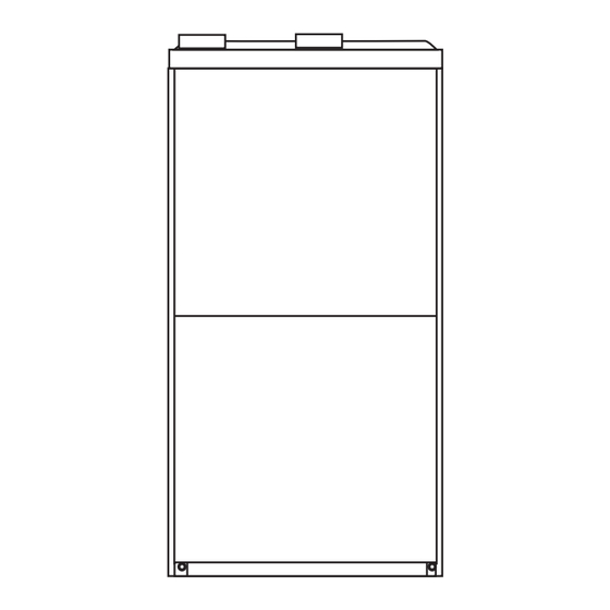
Page 2: Unit Dimensions
Unit Dimensions NOTE - C*20 (5 Ton) size units installed in upflow applications Top View that require air volumes of 1800 cfm (850 L/s) or greater must have one of the following: Single side return air with transition, to accommodate 20 x 25 Exhaust Air x 1 in. -
Page 3: Parts Arrangement
Parts Arrangement Figure 1. Page 3 of 61 Issue 2505 508618-01... -
Page 4: Gas Furnace
1 - Snap Plug return air. 1 - Wire tie The A96UH1EK & 96G1UHEK can be installed as either a 1 - Condensate trap Direct Vent or a Non-Direct Vent gas central furnace. 1 - Condensate trap cap... -
Page 5: Installation Locations
In order to ensure proper unit operation in non-direct vent applications, combustion and ventilation air supply must be provided according to the current National Fuel Gas Code or CSA-B149 standard. Installation Locations This furnace is CSA International certified for installation clearances to combustible material as listed on the unit nameplate and in the table in Figure 13 and Figure 18. -
Page 6: General
INSTRUCTIONS VOIDS MANUFACTURER’S EQUIPMENT LIMITED WARRANTY. ALLIED Combustion, Dilution & Ventilation Air DISCLAIMS ALL LIABILITY IN CONNECTION WITH INSTALLER’S FAILURE TO FOLLOW THE ABOVE If this unit is installed as a Non-Direct Vent Furnace, follow INSTALLATION INSTRUCTIONS. the guidelines in this section. -
Page 7: Unconfined Space
of ANSI on the referenced subject, which is represented may include bleaches, adhesives, detergents, solvents only by the standard in its entirety. and other contaminants which can corrode furnace components. The requirements for providing air for combustion and WARNING ventilation depend largely on whether the furnace is Insufficient combustion air can cause headaches, installed in an unconfined or a confined space. - Page 8 When communicating with the outdoors through horizontal ducts, each opening shall have a minimum free area of 1 square inch (645 mm²) per 2,000 Btu (.56 kW) per hour of the total input rating of all equipment in the enclosure. See Figure 8.
-
Page 9: Installation
Shipping Bolt Removal Units with 1/2 hp & 3/4 hp blower motor are equipped WARNING with three flexible legs and one rigid leg. The rigid leg is equipped with a shipping bolt and a flat white plastic If this unit is being installed in an application with washer (rather than the rubber mounting grommet used combustion air coming in from a space serviced by an with a flexible mounting leg). - Page 10 Tilt the unit slightly (Max. 1/2”) from back to front to aid in the draining of the heat exchanger. Unit must be level side-to-side in all applications. Figure 12. Setting Equipment WARNING Improper installation of the furnace can result in personal injury or death.
-
Page 11: Front View
Return Air Guidelines Return air can be brought in through the bottom or either side of the furnace installed in an upflow application. If the 20” X 25” X 1” furnace is installed on a platform with bottom return, make (508mm X 635mm X 25mm) an airtight seal between the bottom of the furnace and the Air Filter... -
Page 12: Horizontal Applications
(Upflow Applications Only) Right-Hand Discharge Left End Right End Flow Flow Bottom (Floor)** Left-Hand Discharge Left End Right End Flow Flow Bottom (Floor)** Figure 16. Removing the Bottom Panel Top/Plenum 1 in. (25 mm) * Front Removing the Bottom Panel Back Remove the two screws that secure the bottom cap to the Sides... -
Page 13: Filters
NOTE: Heavy-gauge sheet metal straps may be used to Filters suspend the unit from roof rafters or ceiling joists. When straps are used to suspend the unit in this way, support must be provided for both the ends. The straps must not This unit is not equipped with a filter or rack. -
Page 14: Specification
F656 PVC Solvent Cement D2564 IMPORTANT CPVC Solvent Cement F493 A96UH1EK & 96G1UHEK exhaust and intake ABS Solvent Cement D2235 connections are made of PVC. Use PVC primer and solvent cement when using PVC vent pipe. When using PVC/CPVC/ABS All Purpose Cement For... -
Page 15: Joint Cementing Procedure
Standard Concentric Flush Mount Kit Wall Kit 1-1/2 inch 2 inch 3 inch Vent Pipe Dia. Field (in.) 2 inch 3 inch Fabricated 71M80 (US) 69M29 (US) 60L46 (US) 51W11 (US) 44W92 44W92 444W93 22G44 (US) 44J40 (US) 51W12 (CA) (CA) (CA) (CA) -
Page 16: Venting Practices
Removal of the Furnace from Common Vent during assembly (but not after pipe is fully inserted) to distribute cement evenly. Do not turn ABS or cellular In the event that an existing furnace is removed from core pipe. a venting system commonly run with separate gas NOTE: Assembly should be completed within 20 appliances, the venting system is likely to be too large to seconds after last application of cement. -
Page 17: Vent Piping Guidelines
The vent should be checked for different sizes of vent pipe, a combination vent pipe may proper draw with the remaining appliance. be used. Contact Allied Air Technical Service for assistance in sizing vent pipe in these applications. Figure 22. - Page 18 030, 045, Furnace capacity? 070, 090, 110, 135 Standard or Which termination? Concentric? See Table 3 Which needs most Intake or Figure 23. elbows? Exhaust? IMPORTANT Do not use screens or perforated metal in exhaust or intake terminations. Doing so will cause freeze-ups and How many? may block the terminations.
- Page 19 Maximum Allowable Intake or Exhaust Vent Length in Feet Standard Termination at Elevation 0 - 2,000 ft 1-1/2” Pipe 2” Pipe 2-1/2" Pipe 3" Pipe Number Capacity Capacity Capacity Capacity of 90° Elbows 030/ 030/ 030/ 030 045 070 090 110 135 070 090 110 135 070 090 110 135 070 090 110 135...
- Page 20 Maximum Allowable Intake or Exhaust Vent Length in Feet Concentric Termination at Elevation 0 - 2,000 ft 1-1/2” Pipe 2” Pipe 2-1/2" Pipe 3" Pipe Number Capacity Capacity Capacity Capacity of 90° Elbows 030/ 030/ 030/ 030 045 070 090 110 135 070 090 110 135 070 090 110 135 070 090 110 135...
- Page 21 Maximum Allowable Exhaust Vent Lengths With Furnace Installed in a Closet or Basement Using Ventilated Attic or Crawl Space For Intake Air in Feet Standard Termination at Elevation 0 - 2,000 ft 1-1/2” Pipe 2” Pipe 2-1/2" Pipe 3" Pipe Number Capacity Capacity...
- Page 22 TYPICAL EXHAUST PIPE CONNECTIONS IN UPFLOW DIRECT OR NON-DIRECT VENT APPLICATIONS Pipe size determined in Table 5 2” 2” 2” 2” 3” 2” TRANSITION EXHAUST *2” 030/045/070 Only 1-1/2” DO NOT transition from smaller to larger TRANSITION pipe in horizontal runs 2”...
- Page 23 TYPICAL INTAKE PIPE CONNECTIONS IN UPFLOW DIRECT OR NON-DIRECT VENT APPLICATIONS 2” 3” Pipe size determined in Table 5 TRANSITION INTAKE *2” 2” 2” 2” 2” * When transitioning up in pipe size, use the shortest length of 2” PVC pipe possible. NOTE: Exhaust pipe and intake pipe must be the same diameter.
- Page 24 The air intake piping must not terminate too close to TYPICAL AIR INTAKE PIPE CONNECTIONS the flooring or a platform. Ensure that the intake air UPFLOW NON-DIRECT VENT APPLICATIONS inlet will not be obstructed by loose insulation or other items that may clog the debris screen. Intake Debris If intake air is drawn from a ventilated attic (Figure...
- Page 25 NOTE: See Table 6A through Table 6B for maximum allowed exhaust pipe length without insulation in unconditioned space during winter design temperatures Roof Terminated Exhaust Pipe below 32°F (0°C). If required exhaust pipe should be insulated with 1/2” (13 mm) Armaflex or equivalent. In extreme cold climate areas, 3/4”...
- Page 26 Maximum Allowable Exhaust Vent Pipe Length (in ft.) without Insulation in Unconditioned Space For Winter Design Temperatures Single - Stage High Efficiency Furnace Winter Design Unit Input Size Vent Pipe Temperatures Diameter ºF (ºC) 1-1/2 in. 32 to 21 2 in. (0 to -6) 2-1/2 in.
- Page 27 VENT TERMINATION CLEARANCES FOR NON-DIRECT VENT INSTALLATIONS IN THE US AND CANADA INSIDE CORNER DETAIL Fixed Operable Fixed Closed Closed Operable AREA WHERE TERMINAL AIR SUPPLY INLET VENT TERMINAL IS NOT PERMITTED US Installations Canadian Installations Clearance above grade, veranda, 12 inches (305mm) or 12 inches (305mm) 12 inches (305mm) or 12 inches (305mm) porch, deck or balcony...
- Page 28 VENT TERMINATION CLEARANCES FOR DIRECT VENT INSTALLATIONS IN THE USA AND CANADA INSIDE CORNER DETAIL Fixed Operable Fixed Closed Closed Operable AREA WHERE TERMINAL AIR SUPPLY INLET VENT TERMINAL IS NOT PERMITTED US Installations Canadian Installations Clearance above grade, veranda, 12 inches (305mm) or 12 inches (305mm) 12 inches (305mm) or 12 inches (305mm) porch, deck or balcony...
- Page 29 Details of Intake and Exhaust Piping 3” (76MM) MIN. SIZE PER EXHAUST PIPE Inches (MM) Terminations for Direct Vent Installations TERMINATION SIZE NOTE: In Direct Vent installations, combustion air is taken REDUCTION TABLE from outdoors and flue gases are discharged to outdoors. UNCONDITIONED ATTIC SPACE 8”...
- Page 30 FIELD FABRICATED WALL TERMINATION NOTE − FIELD−PROVIDED REDUCER MAY BE 2” (51mm) 3” (76mm) REQUIRED TO ADAPT LARGER VENT PIPE SIZE Vent Pipe Vent Pipe TO TERMINATION A− Minimum clearance above grade or average 12” (305 mm) 12” (305 mm) snow accumulation B−...
- Page 31 On field supplied terminations, a minimum distance DIRECT VENT CONCENTRIC ROOFTOP TERMINATION between the end of the exhaust pipe and the end of 71M80, 69M29 or 60L46 (US) the intake pipe without a termination elbow is 8” and a 44W92 or 44W93 (Canada) minimum distance of 6”...
- Page 32 Details of Exhaust Piping Terminations for Non- If exhaust piping must be run up a sidewall to position above snow accumulation or other obstructions, piping Direct Vent Applications must be supported every 24” (610 mm) as shown in Exhaust pipes may be routed either horizontally through Figure 47.
- Page 33 Exhaust through Crawl Space Vent Option All 33” condensing gas furnaces (92%+) are now approved Exhaust from Furnace to be vented down through a crawl space. Ensure a vent To Termination pipe drain kit, 51W18 (USA) or 15Z70 (Canada), is used as directed through the floor joists and into the crawl space.
-
Page 34: Condensate Piping
Figure 55 and Figure 56 show the furnace and Condensate Piping evaporator coil using a separate drain. If necessary the condensate line from the furnace and evaporator This unit is designed for either right or left side exit of coil can drain together. See Figure 57 and Figure 58. condensate piping in upflow applications. - Page 35 * Piping from furnace must slope down a minimum of 1/4” per ft. toward trap. Figure 53. Condensate Trap Locations (Unit shown in upflow position with remote trap) Figure 54. Condensate Trap with Optional Overflow Switch WARNING When combining the furnace and evaporator coil drains together, the A/C condensate drain outlet must be vented to relieve pressure in order for the furnace pressure switch to operate properly.
- Page 36 * Piping from furnace must slope down a minimum of 1/4” per ft. toward trap. Figure 55. Condensate Trap Locations Figure 56. Unit with Cooling Coil Using Separate Figure 57. Evaporator Coil Using a Common Drain Drain Piping from furnace and evaporator coil must slope down a minimum 1/4” per ft. toward trap. Figure 58.
- Page 37 Figure 59. Trap / Drain Assembly Using 1/2” PVC or 3/4” PVC Page 37 of 61 Issue 2505 508618-01...
-
Page 38: Gas Piping
Gas Piping IMPORTANT Compounds used on threaded joints of gas piping must be resistant to the actions of liquified petroleum gases. CAUTION If a flexible gas connector is required or allowed by the authority that has jurisdiction, black iron pipe shall Leak Check be installed at the gas valve and extend outside the After gas piping is completed, carefully check all field-... - Page 39 Figure 61. Gas Piping Upflow Applications Figure 62. Gas Piping Horizontal Applications Page 39 of 61 Issue 2505 508618-01...
- Page 40 Gas Pipe Capacity - FT³/HR (kL/HR) Nominal Length of Pipe - feet (m) Internal Iron Pipe Diameter Size - - inches inches (3.048) (6.096) (9.144) (12.192) (15.240) (18.288) (21.336) (24.384) (27.432) (30.480) (mm) (mm) .622 (12.7) (17.799) (4.96) (3.40) (2.75) (2.32) (2.07) (1.87)
-
Page 41: Electrical
The unit is equipped with a field makeup box. The makeup Electrical box may be moved to the right side of the furnace to facilitate installation. Seal unused openings on left side with plugs removed from right side. Secure the excess wire ELECTROSTATIC DISCHARGE (ESD) to the existing harness to protect it from damage. - Page 42 Generator Use - Voltage Requirements • The furnace requires 120 volts ± 10% (Range: 108 volts to 132 volts) • The furnace operates at 60 Hz ± 5% (Range: 57 Hz to 63 Hz) • The furnace integrated control requires both proper polarity and proper ground.
- Page 43 BLOWER SPEED CHART FACTORY CONNECTED SPEED TAPS BURNERS UNIT COOL HEAT PARK 030B(E)08K BROWN, BLUE 030B(E)12K BLACK YELLOW FLAME FLAME ROLLOUT FLAME ROLLOUT IGNITER 045B(E)12K SENSOR SWITCH SWITCH 070B(E)12K BLACK BROWN, YELLOW BLUE J159 090C(E)16K BLACK BROWN, YELLOW P159 BLUE 110C(E)20K COMBUSTION BLACK...
-
Page 44: Ignition Control
Ignition Control DIP Switch Settings heat fan-off delay (amount of time that the blower oper- A96UH1EK & 96G1UHEK units are equipped with a sin- ates after the heat demand has been satisfied) may be gle-stage integrated control. This control manages igni-... -
Page 45: Wiring Connections
On Board Links Must NOT Be Cut To Select Thermostat Wiring Connections AC ON System Options Heat / Cool FURNACE OUTDOOR T'STAT TERM. STRIP UNIT DO NOT CUT ANY ON-BOARD LINKS Figure 67 On Board Links Must Be Cut To Select Wiring Connections Thermostat Heat Pump Options... - Page 46 Single Stage, Constant Torque, Non-Communicating 107792-01 Figure 69 TABLE 10 TABLE 11 1/4” QUICK CONNECT TERMINALS THERMOSTAT INPUT TERMINALS HEAT 120V HUM POWER FOR HUMIDIFIER (120 VAC COMMON GROUND LINE INCOMING POWER LINE (120 VAC) 24V AC XFMR TRANSFORMER PRIMARY (120 VAC) CIRC INDOOR BLOWER MOTOR (120 VAC) COOL...
-
Page 47: Ignition Control Diagnostic Codes
IGNITION CONTROL DIAGNOSTIC CODES DIAGNOSTIC CODES / STATUS OF FURNACE CODE IDLE MODE (DECIMALBLINKS AT 1 HERTZ -- 0.5 SECONDS ON, 0.5 SECONDS OFF INDOOR BLOWER OPERATION: CONTINUOUS FAN MODE (COSTANT TORQUE ONLY) INDOOR BLOWER OPERATION: FOLLOWED BY CFM SETTING FOR INDOOR BLOWER (1 SECOND ON, 0.5 SECOND OFF) / CFM SETTING FOR MODE DISPLAYED (VARIALBE SPEED ONLY) COOLING STAGE (1 SECOND ON, 0.5 SECOND OFF) 1 OR 2 DISPLAYED / PAUSE / REPEAT CODES. -
Page 48: Performance Warning
See TABLE 14 for allowable circulation speeds. 2 - When the A96UH1EK & 96G1UHEK is running in the heating mode, the indoor blower will run on the heating speed. See TABLE 13 for allowable heating speeds. -
Page 49: Twinning
The 24 VAC secondary of the two systems must be in Twinning Two A96UH1EK & 96G1UHEK Furnaces phase. All thermostat connections are made to one control only. See diagram below. The control board in this furnace is equipped with a provi- sion to ”twin”... -
Page 50: Low Gwp Application
Low GWP Application WARNING For use with Allied approved evaporator coil and LGWP sensors only. Use original manufacturer recommended LGWP sensors if using non-Allied approved evaporator coil. Figure 71 CONNECTING THE FURNACE CONTROL BOARD SENSOR. TABLE 15 See Figure 72 and follow steps below: DIP Switch Settings 1 - Route sensor wire #1 through provided grommet. - Page 51 FURNACE CONTROL BOARD LOW GWP MODES OF The furnace control board activates the blower (high speed). The blower purges refrigerant from the OPERATION cabinet, plenum, and ductwork. The modes of operation for the furnace control board are 3. After the furnace control board determines the Initializing, Normal, Leak Detected, and Fault.
-
Page 52: Start-Up Procedure
LGWP TEST BUTTON FUNCTIONALITY External Alarm (For applications with external alarms wired directly to the The furnace control board is equipped with a Test/Reset furnace control board) push button. The Test button can be used to perform sev- The furnace control board triggers the external alarm sys- eral functions, depending on the mode of operation of the tem when it enters Leak Detected mode. -
Page 53: Unit Start-Up
Follow the lighting instructions to place the unit into Unit Start-Up operation. Set the thermostat to initiate a heating demand. FOR YOUR SAFETY READ BEFORE OPERATING Allow the burners to fire for approximately 3 minutes. Adjust the thermostat to deactivate the heating demand. -
Page 54: Proper Combustion
If flame is not detected after first ignition trial, the ignition control will repeat steps 3 and 4 four more times before locking out the gas valve. The ignition control will then automatically repeat steps 1 through 6 after 60 minutes. To interrupt the 60 minute period, move thermostat from “Heat”... - Page 55 High Altitude Information NOTE: In Canada, certification for installations at elevations over 4500 feet (1371 m) is the jurisdiction of local authorities. Units may be installed at altitudes up to 10,000 ft. above sea level. See Table 20 for de-rate manifold values. Units installed at altitude of 7501 - 10,000 feet require an orifice change.
-
Page 56: Testing For Proper Venting And Sufficient Combustion Air For Non-Direct Vent Applications
0 - 4500 ft 4501 - 7500 ft 7501 - 10000 ft Capacity (0 - 1,371m) (1371 - 2286m) (2286 - 3048m) 030/045 No Change 11U66 11U69 No Change 11U70 11U68 No Change 11U70 11U64 No Change 11U70 11U64 No Change 11U70 11U68 Pressure switch is factory set. -
Page 57: Other Unit Adjustments
Other Unit Adjustments Primary Limit Blower Speeds The primary limit is located on the heating compartment Follow the steps below to change the blower speeds. vestibule panel. This limit is factory set and requires no adjustment. 1. Turn off electrical power to furnace. Remove blower access panel. -
Page 58: Blower Performance
Blower Performance NOTE: Please refer to the Product Specifications for airflow/blower data. Winterizing and Condensate Trap Care Service 1. Turn off power to the furnace. Have a shallow pan ready to empty condensate water. Remove the clean out cap from the condensate trap WARNING and empty water. -
Page 59: Cleaning The Burner Assembly
18. Mark and disconnect any remaining wiring to heating 39. Secure burner assembly to vestibule panel using four compartment components. Disengage strain relief existing screws. Burners are self aligning to center of bushing and pull wiring and bushing through the hole clam shells. -
Page 60: Planned Service
Repair Parts List The following repair parts are available through Allied Air dealers. When ordering parts, include the complete furnace model number listed on the CSA nameplate. All service must be performed by a licensed professional installer (or equivalent), service agency, or gas supplier. -
Page 61: Requirements For Commonwealth Of Massachusetts
Requirements for Commonwealth of Massachusetts Modifications to NFPA-54, Chapter 10 INSPECTION. The state or local gas inspector of the side wall, horizontally vented, gas-fueled equipment Revise NFPA-54 section 10.8.3 to add the following shall not approve the installation unless, upon requirements: inspection, the inspector observes carbon monoxide For all side wall, horizontally vented, gas-fueled equipment...
Need help?
Do you have a question about the A96UH1EK and is the answer not in the manual?
Questions and answers