
Subscribe to Our Youtube Channel
Related Manuals for Kospel HPM2.C


Summary of Contents for Kospel HPM2.C
- Page 1 HPM2.C Heat Pump HPMD - 8 HPMD - 12 HPMD - 16 HPMO2 - 16/23 HPMO2 - 12 HPMO2 - 8 Installation and Operating Instructions Start-up card...
-
Page 2: Table Of Contents
Contents Explanation of symbols Target group Safety Guidelines Safety tips (cont.), Device description Product Information The installer's responsibilities include: The necessary activities involving the initial start-up include: Activities to be performed during periodic inspection: Noise HPMD Construction HPMO2 Construction Installation Installation (cont.) Connection to the electrical system Opening the HPMD Module... -
Page 3: Explanation Of Symbols
Explanation of symbols Follow the safety instructions carefully in order to prevent injury and damage. Danger This sign warns against danger of injury. Warning This sign warns of the danger of fire. Note This sign warns against property damage and environmental pollution. Text marked with the word Tip contains additional information. -
Page 4: Safety Guidelines
10. The manufacturer is not responsible for the installation of the HPM2.C heat pump with other devices, which may result in incorrect operation, lack of efficient working parameters of the heating system, increased heating system operating costs or failure of the HPM2.C heat pump. -
Page 5: Safety Tips (Cont.)
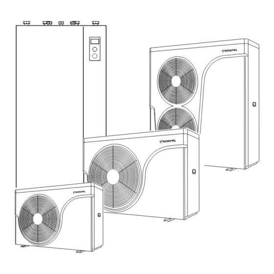
Device description The HPM2.C heat pump is a device intended for heating/cooling the building and heating domestic water. The device consists of two modules: External HPMO2, a compressor heat pump. -
Page 6: Product Information
Product Information External temperature ranges for air/water heat pumps Air/water heat pumps use external air as a heat source. They operate efficiently only within specific external temperature ranges, for example, between -25°C and +43°C. If the upper temperature limit is exceeded or the lower temperature limit is reached, the heat pumps switch off periodically. -
Page 7: The Installer's Responsibilities Include
Noting the appropriate parameters in the form "HPM2.C Heat Pump Commissioning Card" in the user manual. 6. Device registration by the company after performing the Initial Start-up in the Kospel sp. z o.o. "HPM2.C Heat Pump Registration" electronic system, no later than 2 days after starting the device. -
Page 8: Noise
Noise Sound pressure level for different distances from the device. Distance from the noise source r [m] Power level Directivity acoustic factor Lw [dB (A)] Sound pressure level Lp [dB (A)] HPMO2-8 HPMO2-12 HPMO2-16/23 Q = 2: freestanding heat pump on the outside of the building. Q = 4: heat pump on the building's wall. -
Page 9: Hpmd Construction
HPMD Construction [1] - Automatic air vent [11] - Control panel [2] - Heating assembly [12] - Revision hole [3] - Safety valve [13] - Electrical connector [4] - Three-way valve [14] - Cold water supply tube [5] - DHW temperature sensor tube [15] - Control board [6] - Circulation pump [16] - Electronic anti-corrosion protection... -
Page 10: Hpmo2 Construction
HPMO2 Construction Danger Touching components that conduct current can lead to serious injuries caused by electric shock. Some components on the installation plates conduct current even after the power supply is turned off. ■ When working on the external module, disconnect the installation from the power supply, e.g., by a separate fuse or main switch. - Page 11 Outdoor module with two fans: HPMO2-16/23 [1] - Right panel [22] - Four-way valve [2] - Plate heat exchanger bracket [23] - Middle partition assembly [3] - Handel [24] - Suspended Plate [4] - Panel bracket [25] - Front cover [5] - Plate heat exchanger [26] - Fan retainer [6] - Plate heat exchanger...
-
Page 12: Installation
Installation Minimum clearances for the internal module In conjunction with refrigerant R32: Strictly adhere to the minimum room surface area in addition to the minimum distances. min.60 min.100 min.50 min.100 [1] - Outlet to the heat pump 1¼" [2] - Inlet from the heat pump 1¼" [3] - Return from the heating/hot water installation 1¼"... - Page 13 Note Impacts, strong pressure, and high stress can cause damage to the external walls of the device. Do not load the top and front walls as well as the side walls. If several heat pumps are to be installed in one room, the minimum room volume should be calculated for the device with the most refrigerant.
-
Page 14: Installation (Cont.)
Installation (cont.) Outdoor module with one HPMO2-8 fan 1165 G1 heating medium outlet Place that power cord and communication cable enter G1 heating medium inlet Outdoor module with one HPMO2-12 fan 1280 G1 heating medium outlet Place that power cord and communication cable enter G1 heating medium inlet... - Page 15 Outdoor module with two HPMO2-16/23 fans 1240 G1 heating medium outlet G1 heating medium inlet Place where power cord and communication cable enter Transport Note Impacts, strong pressure and high stress can cause damage to the external walls of the device. Do not load the top, front, and side walls.
- Page 16 Influence of weather conditions: When installing in wind-exposed locations, consider wind loads. ■ If installing the external module on a flat roof, significant wind loads can occur depending on the wind load zone and building height. In this case, we recommend commissioning a designer to design the support structure considering the requirements stated in the DIN 1991-1-4 standard.
- Page 17 Minimum distances at the outdoor module Outdoor module with one fan Outdoor module with two fans A - Air outlet B - Air intake EN-117B_f.1558...
- Page 18 Mounting on the ground Foundations Mount the ground installation brackets on two horizontal foundation benches. It is recommended to make a concrete foundation according to the drawing. The given thicknesses of the layers are approximate values. They must be adapted to local conditions. Follow the principles of construction technology.
- Page 19 A - Bed mounting bracket B - Gravel bed to facilitate condensate absorption C - Concrete foundation: see chapter “Foundations”. It is recommended that the condensate drains freely, with no condensate duct. EN-117B_f.1558...
-
Page 20: Connection To The Electrical System
Connection to the electrical system Outdoor module: terminals Outdoor module with 1 fan: opening the connection area HPMO2-8 HPMO2-12 A - Connection area: ■ Communication bus cable for indoor module Electrical terminal of compressor ■ Outdoor module with 2 fans: opening the connection area HPMO2-16/23 A - Communication bus cable to indoor module... -
Page 21: Opening The Hpmd Module
Opening the HPMD Module Internal Module: Front Cover Mounting Note An unsealed housing can lead to damage caused by condensation, vibration, and can contribute to noise generation. The front cover is heavy, special care should be taken when removing it. Remove the front cover by unscrewing the securing screw in the hole at the bottom of the cover with a crosshead screw- driver. - Page 22 Connecting the communication bus wire between the internal and external modules A LIYcY 2x0.5mm cable should be used as the communication bus cable. There is a terminal for grounding the cable screen on the control circuit board. Remove 12mm of insulation from the cable, leaving the screen, place it under the terminal, and tighten it. Connect terminals A and B of the external module with a terminating resistor.
- Page 23 Indoor module: overview of connections Pumps: PHWC - circulating tap water pump PGC - glycol circulation pump PHC1 - CH1 circulation pump (without mixer) PHC2 - CH2 circulation pump (with mixer) PIDU - circulation pump in indoor unit Valves: VCH - cooling / heating switching valve / circulation pump VMHC2 - mixing valve for CH2 circuit VDC - valve switching between domestic hot water...
- Page 24 External UPS Power Source The device is designed to work with an emergency HPMD UPS power supply. In the event of a power outage in the energy network, functions related to protecting the hydraulic system from freezing on the external unit side are maintained.
- Page 25 Electrical Connection When connecting to a single-phase installation, bridges should be used to short the U V W terminals. HPM2.C-8 / HPM2.C-12 HPM2.C-16 HPM2.C-8 / HPM2.C-12 connection to 1-phase installation connection to 3-phase installation connection to 3-phase installation HPMD HPMD HPMD HPMO.2...
-
Page 26: Connection Of External Sensors And Control Devices
Connection of external sensors and control devices Radiator heating circuit temperature sensor WE-019/05 (THC1 input) The location for installing the sensor is shown on the hydraulic installation diagram. The sensor is required if the CH1 circuit is active [Configuration / Service -> Configuration -> CH1 circuit -> circuit: Yes]. Underfloor heating circuit temperature sensor WE-019/05 (THC2 input) The location for installing the sensor is shown on the hydraulic installation diagram. - Page 27 THC1 NW cwu ZA EA THC2 HP.HS.24 PHWC PHC1 PHC2 VMHC2 HPMO2 NW co HPMD THC1 NW cwu ZA EA THC2 HP.HS.24 PHWC PHC2 PHC1 VMHC2 HPMO2 NW co HPMD EN-117B_f.1558...
- Page 28 THC1 NW cwu ZA EA THC2 HP.HS.24 PHWC PHC2 PHC1 VMHC2 HPMO2 NW co HPMD THC1 NW cwu ZA EA THC2 HP.HS.24 PHWC PHC2 PHC1 VMHC2 HPMO2 NW co HPMD HPMO2 - heat pump THC2 - underfloor heating circuit temperature sensor HPMD - hydraulic module VMHC2 - CH2 circuit mixing valve KO - air vent...
-
Page 29: Operation Of Control Panel
Operation of control panel Use the mode selection knob [3] to set one of the modes: winter summer 9:37 Tu 04.02.2020 9:37 Tu 04.02.2020 standby 5,1° 5,1° Turning the navigation knob [2] (left or right), with the winter or summer mode being active, switches the function screens on the display [1]. - Page 30 MAIN SCREEN: [1] - signalling of heat take-up [2] - heating programme on indication [3] - heater on indication 9:37 Tu 04.02.2020 9:37 Tu 04.02.2020 [4] - compressor operation indication [5] - signalling of room temperature set 5,1° 5,1° [6] - room temperature [7] - outdoor temperature 55°...
- Page 31 SETTINGS: Adaptation of the device parameters to the user’s preferences. • Room temperature 9:37 Thu 22.04.2021 9:37 Thu 22.04.2021 Economy , Comfort- , Comfort , Comfort+ : setting the room temperature values available in the schedules Party, Holiday: selection of temperatures to be implemented in programmes Cooling: room temperature setting in the cooling mode (available with active panel cooling) Settings...
- Page 32 • Circulation program (available only within active circulation in system DHW) [1] - no. of time frame according to schedule (max 5) Circulation program Circulation program [2] - start time of circulation pump operation [3] - finish time of circulation pump operation 1 6:00 - 8:00 2 18:30 - 23:00 2 18:30 - 23:00...
- Page 33 • LANGUAGE choice of language menu • SYSTEM: MSPC PROGRAM: shows the version of indoor unit controllers program PW PROGRAM: shows the version of panel’s program RESET: heat pump’s start-up FACTORY SETTINGS: restore SERVICE / CONFIGURATION: Configuration 9:37 Thu 22.04.2021 9:37 Thu 22.04.2021 Adaptation of the heat pump: Service / Configuration...
- Page 34 • CH1 circuit: Heating curve no.: selection of a heating curve (see Chapter Heating curve). Hint: the parameter is present when the control is set according to heating curve [Configuration -> Heating -> Regulation type: Acc. curve], Curve offset: Heating curve offset (see section Curve heating). Hint: that the parameter is present when the control is set according to heating curve [Configuration ->...
- Page 35 • Cylinder: Time without immersion heater: the parameter defines the time after which the heat pump is supported it will be an addi- tional source of heat (immersion heater) if it does not reach the set value water temperature in the tank. Time is counted from the moment of reaching temperature of bivalent point [Configuration ->...
- Page 36 PARTY / HOLIDAY / MANUAL Quickly switch the hot water algorithm as required. 8:38 THU 14.04.2020 8:38 THU 14.04.2020 • Party: setting the duration of the mode (from 1 to 24 hours or until cancelled). • Holiday: setting the duration of the mode (from 1 to 60 days or until cancelled). •...
- Page 37 Heating curve The purpose of the heat pump controller is to maintain the temperature in the central heating system depending on the outdoor temperature. When the temperature outside the building is low, the need for heat is greater, whereas if the temperature outdoors is high, there is no need to maintain a high temperature in the system.
-
Page 38: Incorrect Operation Of The Device
Incorrect operation of the device The room temperature is too low Cause Remedial action ■ Switch on the power switch The heat pump is switched ■ Switch on the main switch (if installed, outside the boiler room). off. ■ Switch on the fuse in the electrical switchboard (the house fuse). Space heating/cooling must be activated. -
Page 39: Cleaning
„Warning” Cause Remedial action Warning concerning special occurrence, operating condition of If necessary, contact an Authorised Service Centre heat pump, heating system „Fault” Cause Remedial action Fault in heat pump or in heating If necessary, contact an Authorised Service Centre system Cleaning Note... -
Page 40: Keeping The Device In Good Technical Condition
Keeping the device in good technical condition Checklist in relation to keeping the device in good technical shape For systems with flammable refrigerants • Anyone working on a refrigeration system is required to submit a proof of qualification issued by an accredited body authorised to issue industry certifications. - Page 41 Only those components that meet the requirements for operation in a flammable ■ atmosphere may be connected to voltage in a flammable atmosphere. Use only original spare parts or parts approved by the Kospel company. In the event of ■ a leak, all other parts may ignite the refrigerant.
- Page 42 Wiring ■ Check that the wiring is not exposed to wear, corrosion, stretching, vibration or any adverse environmental conditions and that it is not located near sharp edges. ■ When inspecting, also consider the effects of ageing and the effects of continuous vibration on the compressors and fans.
-
Page 43: Check-Up Of Temperature Sensor
Check-up of temperature sensor Connection to indoor module The temperature sensors are connected to a low-voltage printed circuit board. Temperature sensor Measuring element ■ Outdoor temperature sensor WE-027 NTC 10 kΩ ■ Buffer storage tank temperature sensor WE-019/01 ■ Water temperature sensor in hot tap water storage tank, WE-019/01 ■... -
Page 44: Final Decommissioning And Disposal
Final decommissioning and disposal The products may be recycled. The components and consumables must not be disposed of in municipal waste. To decommission the installation, disconnect the electrical supply and allow the components to cool down. All the components must be expertly disposed of. Consumables (e.g. -
Page 45: Technical Data
Technical data OUTDOOR UNIT HPMO2-8 HPMO2-12 HPMO2-16/23 Heating power A+2/W35 11,3 20,5 Power consumption A+2/W35 1,78 2,87 5,11 Efficiency factor A+2/W35 4,01 3,94 4,02 Heating power A+7/W35 2,3 - 8,2 3,8 - 12,5 7,0 - 23,0 Power consumption A+7/W35 0,5 - 1,84 0,8 - 2,95 1,47 - 5,9 Efficiency factor A+7/W35... - Page 46 Maximum operating pressure of refrigerant High pressure side Low pressure side Amount of refrigerant GWP of refrigerant AR4 (according to IPCC 0,675 0,675 0,675 Fourth Assessment Report) equivalent 0,743 1,215 1,350 Dimensions (HxWxD) 795 x 1165 x 450 928 x 1280 x 500 1329 x 1240 x 540 Mass INDOOR UNIT...
-
Page 47: Product Sheet
Product Sheet Supplier name or trademark KOSPEL.Sp z o.o. HPM2.C-8 HPM2.C-12 HPM2.C-16 Supplier model identifier (HPMO2-8 (HPMO2-12 (HPMO2-16/23 + HPMD-8) + HPMD-12) + HPMD-16) Declared load profile Seasonal energy efficiency class for room heating for the model in moderate climate conditions (*) - Page 48 Energy efficiency class of temperature controller The product data listed corresponds to the requirements of EU Regulation 811/2013. Energy efficiency class of Contribution to the energy Criterion temperature controller efficiency of space heating • Room thermostat for switching the heat generator on/off •...
- Page 49 Heat pump HPM2.C Kospel Sp. z o.o. start-up card Start-up date Assembly address Stamp Certi cate no. Installer's data Outdoor unit no. Indoor unit no. C.MI2 module no. Data Type of plate exchanger DHW cylinder type Buffer CH type Data of additional devices...
-
Page 50: Packaging Contents
Declaration of conformity; reference standards and directives KOSPEL Sp. z o.o. declares with full responsibility that the HPM2.C Heat Pump mentioned in this user manual complies with the requirements of Directives and corresponding safety standards for electrical appliances for household use:... - Page 52 KOSPEL Sp. z o.o. 75-136 Koszalin, ul. Olchowa 1, Poland tel. +48 94 31 70 565 serwis@kospel.pl www.kospel.pl Made in Poland...
Need help?
Do you have a question about the HPM2.C and is the answer not in the manual?
Questions and answers