Advertisement
Quick Links
Advertisement

Related Manuals for Kospel HPI-4


Summary of Contents for Kospel HPI-4
- Page 1 HEAT PUMP HPI-4...
-
Page 2: Safety Instructions
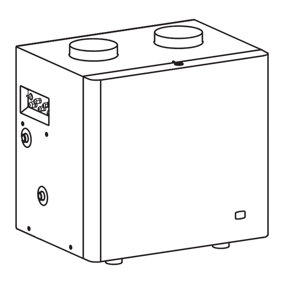
Safety instructions Please read and follow the Installation and Operating Instructions carefully, to ensure the long life and reliable operation of this appliance. Installation and use of heat pump inconsistent with this instruction is not permit- ted - may cause malfunction and will void the warranty. The device must not be installed in unheated rooms. The minimum air intake temperature 5°C. Mounting and commissioning of the heat pump and accompanying installation should be entrusted to a specialist service company. The heat pump should be installed only in horizontal position on a flat surface with appropriate lifting capacity or on a suitable supports on the wall. The device must be installed in such a place and in a such a way that the emergency leakage from connectors would not cause flooding of the room. The room must have a possibility to drain condensate to the sewer. After setting up, the device must be connected to the cylinder as described in contained manual. Inconsistence with the description of the connection invali- dates the warranty and may cause malfunction. 10. The heat pump unit is designed to connect to installation with pressure not exceeding 0,6 MPa. If the water pressure exceeds 0,6 MPa, install a pressure reducing valve in front of the machine. - Page 3 Description The heat pump HPI-4 is used to heat sanitary water. The unit derives heat from surrounding air and passes through the water by electrically powered compressor refrigerant circuit. The heat pump HPI-4 can be used to supply water storage tanks with a capacity of 100 - 400dm [1] - air outlet [10] - water outlet G3/4” [2] - pipecross valve [11] - condensate outlet [3] - air inlet...
- Page 4 The device is designed for co-operating with hot water cylinder connected to plumbing and protected against ex- cessive pressure according to PN-76 /B-02440. The heat pump HPI-4 is a Inlet TZAS pressure device adapted to connection to plumbing pressure not exceeding Outlet 0,6MPa. At the inlet of water into the...
- Page 5 Air cables connection air inlet air outlet Air can be extracted from the room in which the device is mounted, another Ø200 room or from the outside of the building. In the second and third case, the device Ø200 should result in appropriate air ducts. In the case where the air intake on the air outlet are on one wall at a distance of less than 4 meters, on the air there must be a moulder directing air flow in a direction opposite to the air intake. At the inlet and air outlet there are DN200 connectors. The installation should be made of DN200 pipe using reducing heat pump fittings on a connections. In order to achieve optimal device param- eters, ensure that the air flow of at 800 /h. To minimize losses associated with air resistance, the cable must be performed in a straight line. For DN200 the total length of the inlet and air outlet...
-
Page 6: Air Filter
Air filter On the inlet of the device there is an air filter mounted, and at least once a year the cleanness should be checked and replaced if necessary. Designation of filter - pocket filter 287 x 287 x 200 with filtration class G3. Pull the pocket vigorously and move Tilt the filter to the bottom and pull the filter maximum to the right out of the handle Connecting of the condensate hose During normal operation, moisture in the air condenses on the walls of evaporator. Condensates flow into the drip tray where are led to the tube nozzle on the outside of the device. During the operation of the pump, fan creates under pressure inside, to allow free drainage of condensate, siphon should be installed to the drain pipe. -
Page 7: Temperature Regulator
Connection to the electric installation The device must be connected to the electrical system using the attached cable sec- tion 3 x 1mm ended with a plug. The electrical system shall be equipped with a residual current protective devices. LED 485 TZAS TS1 TS2 TD TG1 TG2 SG SW K A B A +5 S G In order to allow interaction with other devices the driver is equipped with SG and NA clamps. SG (max.0,1A 250V ~) - relay output excluding slave device; during operation of the heat pump output circuit connected to SG is open. „NA” (input voltage free) - input of the master device; opening the contact of „NA” disables starting the device. While connecting to the clamps „NA” the master device (eg. time switch or temperature regulator) switch pos. [6] switch to „ON” , and in the case of connecting temperature regulator the N03 setting should be changed to „OFF” position and then unplug TZAS sensor. - Page 8 Start-up Before starting the unit, visually check the connection of the device and proper instal- lation in accordance with the diagrams. The tank must be filled with water: open the valve on the cold water inlet, open the valve on the hot water outlet installation (full flow of the water stream, without air bubbles indicates that the tank is full, close the taps. Check for leaks of the sanitary hot water side. Check the operation of the safety valve (in accordance with the valve’s manufacturer instruction). Check the connection of air ducts. Check the electrical connection. Connect the switch [6] on the “ON” position, the unit will process with factory settings. The heat pump controller The heat pump controller is located under the cover. To remove the cover twist locks on the upper and lower part thereof as shown on the picture. Functions of the controller buttons: a) Selection mode of displayed informa- tion. Indication markings: B (ERRORS) - Error display mode, available if the device diagnoses the fault, (SERVICE) - service mode, N (SETTINGS) - setting mode...
- Page 9 ERR error COM communication with the master device STAT status of the device ▲ Modes B; S and P are available for service purposes. ERR COM STAT Temperature of cylinder 0°C, if N03 setting chosen - „off” displayed value „0” Intake air temperature °C Change parameters of settings: 1. Select (a) setting mode (highlighted indicator N), then sequently on the display will appear setting number and setting value. 2. Select setting using (b) and (c). 3. Using button (d) enter setting change mode (indicator N starts flashing). 4. Change setting by using (b) and (c). 5. Using button (d) exit change setting mode (indicator N stops flashing). N01 set point temperature in the tank 20 - 55°C - factory setting 50°C N02 minimum temperature for the lower source (air) 5 - 15°C - factory setting 10°C N03 deactivating of the temperature sensor in the tank „on-off” factory setting „on” GB-066B_f.
-
Page 10: Technical Data
Technical data Model HPI-4 A20/W35 A7/W35 Heating power (wg EN 14511) A20/W45 A7/W45 A20/W35 A7/W35 COP (wg EN 14511) efficiency factor A20/W45 A7/W45 Power supply ~V/Hz 230/50 Power consumption Number of compressors pcs. The maximum pressure of the refrigerant Refrigerant type R407C Refrigerant volume 1250 Maximum water temperature °C Rated water pressure Water flow rate Available pump pressure Air flow Available static pressure Surrounding temperature °C 5 ÷ 40 Dimensions (H x W x D) 673 x 690 x 520 Weight Noise level... - Page 11 This product must not be treated as a communal waste. Dismantled appliance ought to be given to an appropriate recycling point for electrical and electronic waste. Appropriate disposal of the used product prevents potential negative influence on the environment, which could occur in case of an improper waste disposal. In order to obtain more detailed information on the recycling of the product, contact your local authority, refuse disposal services or the store, where the product has been purchased.
- Page 12 KOSPEL S.A. ul. Olchowa 1 75-136 Koszalin tel. +48 94 31 70 565 serwis@kospel.pl www.kospel.pl...
Need help?
Do you have a question about the HPI-4 and is the answer not in the manual?
Questions and answers