Chapters
Table of Contents

Related Manuals for Hinkley SCULPT 60


Summary of Contents for Hinkley SCULPT 60
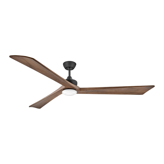
- Page 1 60" SCULPT ™ INDOOR / OUTDOOR LED FAN READY TO USE. CONTROL PRE-PAIRED. CONTROL DC MOTOR CEILING FAN INSTRUCTION MANUAL PAIR WITH HINKLEY APP DOWNLOAD ON APP STORE or GOOGLE PLAY HINKLEY...
- Page 2 SO WE’RE HERE IF YOU HAVE A QUESTION, NEED SOME HELP OR WANT TO CHAT ABOUT OUR PRODUCTS. SEND SUGGESTIONS OUR WAY TOO—WE’RE ALWAYS LOOKING TO MAKE YOUR EXPERIENCE WITH HINKLEY A POSITIVE ONE. > SERVICE@HINKLEY.COM > 800.HINKLEY > LET’S SEE THAT HINKLEY STYLE @Hinkleylighting...
-
Page 3: Table Of Contents
NOTE: If PAIRING is necessary, refer to the control pairing instruction PRE-PAIRED. in the operation section of this Instruction Manual. WARNING: Read and follow these instructions carefully and be mindful of all warnings shown throughout. ©2023 Hinkley Lighting, Inc. | hinkley.com |... -
Page 4: Instructions
If the battery compartment does not close securely, stop using the product and keep it away from children. If you think batteries might have been swallowed or placed inside any part of the body, seek immediate medical attention. | hinkley.com... -
Page 5: Important Safety Precautions
These factors must be supplied by the person(s) installing, caring for and operating the unit. TOOLS & MATERIALS REQUIRED • PHILLIPS SCREWDRIVER • FLAT SCREWDRIVER • WRENCH OR PLIERS • WIRE CUTTER • STEPLADDER • WIRING SUPPLIES AS REQUIRED BY ELECTRICAL CODE ©2023 Hinkley Lighting, Inc. | hinkley.com |... -
Page 6: Unpacking Your Fan
Blade to Motor Screws w/Lock MH903660 Washers, Balance Kit, Safety cable hardware (wood screw, flat washer), Allen wrench, Lead Wire Extension. NOTE: Design of parts shown above may look slightly different for your specific model of fan. XX=FAN FINISH | hinkley.com... -
Page 7: Preparation
The outlet box must be able to support a minimum of 35 pounds. Attach hanging bracket to outlet box using screws Flat washer provided with the outlet box. Spring washer Outlet box screw Fig. 1 ©2023 Hinkley Lighting, Inc. | hinkley.com |... -
Page 8: Hanging The Fan
Safety cable Tighten security set screws against downrod using a large Lead wires flat blade screwdriver to ensure a tight fit against downrod. Downrod Mounting collar Security screws Downrod pin Cotter pin Fig. 2 | hinkley.com... - Page 9 Firmly Wood screw and washer tighten screw in the clamp. Cut off excess cable and tighten the wood screw to ceiling joist. Safety cable Fig. 4 ©2023 Hinkley Lighting, Inc. | hinkley.com |...
-
Page 10: Electrical Connections
GREEN ground wires from the fan and controller. Turn the wire nut connections upward, spreading them apart so the green (ground) and white wires will be on one side of the outlet box and the black wire will be on the other side. Fig. 2 | hinkley.com... - Page 11 Make sure the hook on the hanging bracket properly sits in the groove in the hanger ball before attaching the canopy to the bracket by turning the housing until it drops into place. Fig. 1 ©2023 Hinkley Lighting, Inc. | hinkley.com |...
-
Page 12: Installation Of The Blades
Repeat this process to attach the other blades. Blades NOTE: Blade support plates Cordless power screwdrivers are NOT recommended, as they usually strip the heads of the screws and Screws usually will not fully compress the lock washers on the motor screws. Fig. 1 | hinkley.com... - Page 13 Restore power and your light kit is ready for operation. previously removed. Remove one of the three screws on the adapter plate located on the fan motor. Loosen the other 2 screws. (Do not remove) (Fig. 2) ©2023 Hinkley Lighting, Inc. | hinkley.com |...
- Page 14 Metal cover Allen screws Allen wrench Fig. 1 Mounting hub (bottom of motor) Adapter plate Screws Metal cover Allen screws Allen wrench Fig. 2 | hinkley.com...
-
Page 15: Installing The Wall Control
Remote transmitter will be held in place with built in magnets. Cradle B Wall plate Plastic Face plate anchor Transmitter Outlet box Wall plate Cradle A Face plate Transmitter Wall Fig. 1 HIRO Control System Fig. 2 ©2023 Hinkley Lighting, Inc. | hinkley.com |... - Page 16 Attach the cradle A to the wall switch box using the supplied hardware. Attach the multi-gang faceplate (not provided) to the switch set in the wall outlet box. Cradle A of Hinkley switch will fit in any standard decora face plate.
-
Page 17: Operation
NOTE: A single fan can be controlled with as many as 3 wall controls in one room. Every control will need to repeat the pairing process based on instructions above and all controls must be within 30 feet of the fan. ©2023 Hinkley Lighting, Inc. | hinkley.com |... - Page 18 An UPWARD airflow moves warmer air off the ceiling area as shown in Figure 4. This allows you to set your heating unit on a cooler setting without affecting your comfort. Airflow direction can be changed between summer mode and winter mode by pressing the reverse button on the HIRO control. SUMMER MODE WINTER MODE (COUNTERCLOCKWISE DIRECTION) (CLOCKWISE DIRECTION) Fig. 3 Fig. 4 | hinkley.com...
-
Page 19: Care And Cleaning
If the blade wobble is still noticeable, interchanging two adjacent (side by side) blades can redistribute the weight and possibly result in smoother operation. Make sure the mounting plate is securely fastened to the ceiling outlet box. Make sure ceiling box is secure. ©2023 Hinkley Lighting, Inc. | hinkley.com |... -
Page 20: Energy Guide
• Your cost depends on rates and use • Energy Use: 22 Watts RPMs All estimates based on typical use, excluding lights ftc.gov/energy Airflow Shown Is a Weighted Average of High and Low Cubic Feet per Minute Based on Close to Ceiling | hinkley.com... - Page 21 In addition to the included wall control, you can control your Hinkley fan through the Hinkley app. • To use the Hinkley app, download it for free from the App Store or Google Play. • Open the Hinkley app where you will be prompted to create an account.
- Page 22 HINKLEY IS PROUD TO PROVIDE YOU WITH CEILING FAN PRODUCTS THAT ENHANCE YOUR SPACE WITH COMFORT, PURPOSE AND STYLE. AS A FAMILY COMPANY, WE ARE COMMITTED TO DESIGN, PERFORMANCE AND QUALITY, AND WHAT’S IMPORTANT TO YOU IS PARAMOUNT TO US.
- Page 23 GLOBAL HEADQUARTERS 33000 Pin Oak Parkway | Avon Lake, Ohio 44012 T (440) 653 5500 | F (440) 653 5555 | hinkley.com...
- Page 24 60" SCULPT ™ INDOOR / OUTDOOR LED FAN LISTO USAR. MANDO PREPARADO. CONTROL DC MOTOR MANUAL DE INSTRUCCIONES DEL VENTILADOR DE TECHO EMPAREJAR CON LA APLICACIÓN HINKLEY DESCARGAR EN APP STORE o GOOGLE PLAY HINKLEY...
- Page 25 Si no está familiarizado o no se siente cómodo con el cableado, comuníquese con un electricista calificado. Si necesita asistencia adicional o tiene alguna pregunta, comuníquese con nosotros. Para obtener información sobre la garantía, visite hinkley.com.
- Page 26 PREPARADO. de controles en la sección de operación de este Manual de instrucciones. WARNING: Lea y siga estas instrucciones atentamente y tenga en cuenta todas las advertencias que se muestran en todas partes. ©2023 Hinkley Lighting, Inc. | hinkley.com |...
-
Page 27: Instrucciones Generales De
Si el compartimento de la batería no cierra de forma segura, deje de usar el producto y manténgalo alejado de los niños. Si cree que las pilas pueden haber sido ingeridas o colocadas dentro de cualquier parte del cuerpo, busque atención médica inmediata. | hinkley.com... -
Page 28: Precauciones De Seguridad
TOOLS & MATERIALS REQUIRED • DESTORNILLADOR PHILLIPS • DESTORNILLADOR PLANO • LLAVE O PINZAS • CORTADOR DE CABLES • ESCALERA DE TIJERA • SUMINISTROS DE CABLEADO SEGÚN LO REQUIERE EL CÓDIGO ELÉCTRICO ©2023 Hinkley Lighting, Inc. | hinkley.com |... -
Page 29: Desembalando Tu Ventilador
Hardware del cable de seguridad (tornillo para madera, arandela plana), llave Allen, extensión NOTA: El diseño de las piezas que se muestran arriba puede del cable conductor. parecer ligeramente diferente para su modelo específico de ventilador. XX=ACABADO DEL VENTILADOR | hinkley.com... -
Page 30: Preparación
La caja eléctrica debe poder soportar un mínimo de 35 libras. Arandela plana Arandela de resorte Fije el soporte para colgar a la caja eléctrica utilizando los Tornillo de la caja de tornillos proporcionados con la caja eléctrica. salida Fig. 1 ©2023 Hinkley Lighting, Inc. | hinkley.com |... -
Page 31: Colgar El Ventilador
Apriete los tornillos de seguridad contra la varilla con un destornillador grande de punta plana para asegurar un ajuste perfecto contra la varilla. varilla de descenso Collar de montaje Tornillos de seguridad Pasador de pasador de varilla chaveta Fig. 2 | hinkley.com... - Page 32 Apriete firmemente el tornillo madera de la abrazadera. Corte el exceso de cable y apriete el tornillo para madera a la viga del techo. Cable de seguridad Fig. 4 ©2023 Hinkley Lighting, Inc. | hinkley.com |...
-
Page 33: Conexiones Eléctricas
Gire las conexiones de las tuercas para cables hacia arriba, separándolas de modo que los cables verde (tierra) y blanco queden en un lado de la caja eléctrica y el cable negro en el otro lado. Fig. 2 | hinkley.com... - Page 34 Asegúrese de que el gancho del soporte para colgar se asiente correctamente en la ranura de la bola para colgar antes de fijar la cubierta al soporte girando la carcasa hasta que encaje en su lugar. Fig. 1 ©2023 Hinkley Lighting, Inc. | hinkley.com |...
- Page 35 Placas de soporte NOTA: de cuchillas NO se recomiendan los destornilladores eléctricos inalámbricos, ya que generalmente pelan las cabezas Tornillos de los tornillos y generalmente no comprimen completamente las arandelas de seguridad de los Fig. 1 tornillos del motor. | hinkley.com...
- Page 36 Restablezca la energía y su kit de iluminación estará listo para Retire uno de los tres tornillos de la placa adaptadora funcionar. ubicada en el motor del ventilador. Afloje los otros 2 tornillos. (No quitar) (Fig. 2) ©2023 Hinkley Lighting, Inc. | hinkley.com |...
- Page 37 Cubierta metálica tornillos allen llave Allen Fig. 1 Centro de montaje (parte inferior del motor) Placa adaptadora Tornillos Cubierta metálica tornillos allen llave Allen Fig. 2 | hinkley.com...
-
Page 38: Instalación Del Control De Pared
El transmisor remoto se mantendrá en su lugar con imanes placa de pared Cuna B integrados. El plastico placa frontal ancla Caja de salida Transmisor placa de pared Cuna A placa frontal Transmisor Wall Fig. 1 Sistema de control HIRO Fig. 2 ©2023 Hinkley Lighting, Inc. | hinkley.com |... - Page 39 Conecte la placa frontal de múltiples salidas (no incluida) al juego de interruptores en la caja eléctrica de pared. El soporte A del interruptor Hinkley encaja en cualquier placa frontal decorativa estándar. El transmisor remoto se mantendrá en su lugar con imanes integrados.
- Page 40 3 controles de pared en una habitación. Cada control deberá repetir el proceso de emparejamiento según las instrucciones anteriores y todos los controles deben estar a menos de 30 pies del ventilador. ©2023 Hinkley Lighting, Inc. | hinkley.com |...
- Page 41 La dirección del flujo de aire se puede cambiar entre el modo verano y el modo invierno presionando el botón de retroceso en el control Hiro. MODO VERANO MODO INVIERNO (SENTIDO DE LAS AGUJAS DEL RELOJ) (SENTIDO ANTIHORARIO) Fig. 3 Fig. 4 | hinkley.com...
-
Page 42: Cuidado Y Limpieza
3. Asegúrese de que la placa de montaje esté bien sujeta a la caja eléctrica del techo. 4. Asegúrese de que la caja del techo esté segura. ©2023 Hinkley Lighting, Inc. | hinkley.com |... -
Page 43: Guía Energética
Todas las estimaciones se basan en el uso típico, excluidas las luces. ftc.gov/energy El flujo de aire que se muestra es un promedio ponderado de pies cúbicos por minuto alto y bajo basado en la proximidad al techo. | hinkley.com... - Page 44 Hinkley a través de la aplicación Hinkley. • Para utilizar la aplicación Hinkley, descárguela gratis de App Store o Google Play. • Abra la aplicación Hinkley donde se le pedirá que cree una cuenta. • Ingrese toda la información necesaria para crear una cuenta.
- Page 45 HINKLEY ESTÁ ORGULLOSO DE OFRECERLE PRODUCTOS DE VENTILADORES DE TECHO QUE MEJORAN SU ESPACIO CON COMODIDAD, PROPÓSITO Y ESTILO. COMO EMPRESA FAMILIAR, ESTAMOS COMPROMETIDOS CON EL DISEÑO, EL RENDIMIENTO Y LA CALIDAD, Y LO QUE ES IMPORTANTE PARA USTED ES LO PRIORITARIO PARA NOSOTROS.
- Page 46 GLOBAL HEADQUARTERS 33000 Pin Oak Parkway | Avon Lake, Ohio 44012 T (440) 653 5500 | F (440) 653 5555 | hinkley.com...
- Page 47 60" SCULPT ™ INDOOR / OUTDOOR LED FAN PRÊT UTILISER. COMMANDE PRÉ- CONTROL DC MOTOR APPARIÉE. MANUEL D'INSTRUCTIONS DU VENTILATEUR DE PLAFOND Associer avec l'application HINKLEY TÉLÉCHARGER SUR APP STORE ou GOOGLE PLAY HINKLEY...
- Page 48 Si vous n'êtes pas familier ou mal à l'aise avec le câblage, veuillez contacter un électricien qualifié. Si vous avez besoin d'aide supplémentaire ou avez des questions, n'hésitez pas à nous contacter. Pour plus d’informations sur la garantie, visitez hinkley.com.
- Page 49 REMARQUE : Si un APPAIRAGE est nécessaire, reportez-vous aux instructions CONTRÔLE d'appariement des commandes dans la section Fonctionnement de ce manuel PRÉ-ASSOCIÉ. d'instructions. AVERTISSEMENT: Lisez et suivez attentivement ces instructions et soyez attentif à tous les avertissements qui y figurent. ©2023 Hinkley Lighting, Inc. | hinkley.com |...
-
Page 50: Instructions Générales D'installation Et
Si le compartiment à piles ne se ferme pas correctement, arrêtez d'utiliser le produit et gardez-le hors de portée des enfants. Si vous pensez que des piles ont pu être avalées ou placées dans une partie quelconque du corps, consultez immédiatement un médecin. | hinkley.com... -
Page 51: Précautions De Sécurité Importantes
être intégrés à ce produit. Ces facteurs doivent être fournis par la ou les personnes qui installent, entretiennent et utilisent l'unité. OUTILS ET MATÉRIAUX REQUIS • TOURNEVIS CRUCIFORME • TOURNEVIS PLAT • CLÉ OU PINCE • COUPE-FIL • ESCABEAU • FOURNITURES DE CÂBLAGE COMME REQUIS PAR LE CODE ÉLECTRIQUE ©2023 Hinkley Lighting, Inc. | hinkley.com |... -
Page 52: Déballage De Votre Ventilateur
Matériel de câble de sécurité (vis à bois, rondelle plate), clé Allen, rallonge de fil de plomb. REMARQUE : La conception des pièces illustrées ci-dessus peut être légèrement différente pour votre modèle spécifique de ventilateur. XX=FINITION VENTILATEUR | hinkley.com... -
Page 53: Préparation
35 livres. Fixez le support de suspension à la boîte de sortie à l’aide des Rondelle plate vis fournies avec la boîte de sortie. Rondelle élastique Vis de boîte de sortie Fig. 1 ©2023 Hinkley Lighting, Inc. | hinkley.com |... -
Page 54: Suspendre Le Ventilateur
Serrez les vis de sécurité contre la tige de suspension à Tige de suspension l'aide d'un grand tournevis à lame plate pour garantir un ajustement serré contre la tige de suspension. Collier de montage Vis de sécurité Goupille de tige goupille de suspension Fig. 2 | hinkley.com... - Page 55 Insérez l'extrémité du câble dans la pince et faites passer autant de câble que possible. Serrez fermement la vis dans la pince. Coupez l'excédent de câble et serrez la vis à bois sur la solive du plafond. Câble de sécurité Fig. 4 ©2023 Hinkley Lighting, Inc. | hinkley.com |...
-
Page 56: Connections Electriques
Tournez les connexions des serre-fils vers le haut, en les écartant de manière à ce que les fils vert (terre) et blanc soient d'un côté de Fig. 2 la boîte de sortie et le fil noir de l'autre côté. | hinkley.com... - Page 57 Assurez-vous que le crochet du support de suspension est correctement placé dans la rainure de la boule de suspension avant de fixer l'auvent au support en tournant le boîtier jusqu'à ce qu'il se mette en place. Fig. 1 ©2023 Hinkley Lighting, Inc. | hinkley.com |...
-
Page 58: Installation Des Lames
Plaques support de lame Les tournevis électriques sans fil ne sont PAS recommandés, car ils dénudent généralement les têtes des vis et ne compriment Des vis généralement pas complètement les rondelles de blocage des vis du moteur. Fig. 1 | hinkley.com... - Page 59 Rétablissez l'alimentation et votre kit d'éclairage est prêt à fonctionner. Retirez l'une des trois vis de la plaque d'adaptation située sur le moteur du ventilateur. Desserrez les 2 autres vis. (Ne pas retirer) (Fig. 2) ©2023 Hinkley Lighting, Inc. | hinkley.com |...
- Page 60 ; il peut être enregistré pour une utilisation ultérieure si vous le souhaitez. Couverture métallique clé Allen Fig. 1 Moyeu de montage (bas du moteur) Plaque d'adaptation Des vis Couverture métallique Allen clé Allen Fig. 2 | hinkley.com...
-
Page 61: Installation De La Commande Murale
L'émetteur à distance sera maintenu en place avec des aimants intégrés. plaque murale Berceau B Plastique Plaque frontale ancre Boîte de sortie Émetteur plaque murale Berceau A Plaque frontale Émetteur Wall Fig. 1 Système de contrôle HIRO Fig. 2 ©2023 Hinkley Lighting, Inc. | hinkley.com |... - Page 62 Fixez le support A au boîtier d'interrupteur mural à l'aide du matériel fourni. Fixez la façade multi-groupes (non fournie) à l'interrupteur situé dans la boîte de prise murale. Le berceau A de l'interrupteur Hinkley s'adapte à n'importe quelle plaque frontale Decora standard.
-
Page 63: Opération
3 commandes murales dans une pièce. Chaque commande devra répéter le processus de couplage en fonction des instructions ci-dessus et toutes les commandes doivent se trouver à moins de 30 pieds du ventilateur. ©2023 Hinkley Lighting, Inc. | hinkley.com |... - Page 64 La direction du flux d'air peut être modifiée entre le mode été et le mode hiver en appuyant sur le bouton d'inversion MODE HIVER MODE ÉTÉ (DANS LE SENS DES AIGUILLES D'UNE MONTRE) (SENS ANTI-HORAIRE) Fig. 3 Fig. 4 | hinkley.com...
-
Page 65: Entretien Et Nettoyage
éventuellement entraîner un fonctionnement plus fluide. 3. Assurez-vous que la plaque de montage est solidement fixée au boîtier de sortie au plafond. 4. Assurez-vous que le boîtier de plafond est sécurisé. ©2023 Hinkley Lighting, Inc. | hinkley.com |... -
Page 66: Guide Énergie
• Consommation d'énergie : 22 watts Toutes les estimations sont basées sur une utilisation typique, à l'exclusion des lumières ftc.gov/energy Le débit d'air indiqué est une moyenne pondérée de pieds cubes hauts et bas par minute, basée sur la proximité du plafond. | hinkley.com... - Page 67 Hinkley via l'application Hinkley. • Pour utiliser l'application Hinkley, téléchargez-la gratuitement depuis l'App Store ou Google Play. • Ouvrez l'application Hinkley où vous serez invité à créer un compte. • Entrez toutes les informations nécessaires pour créer un compte.
- Page 68 HINKLEY EST FIER DE VOUS PROPOSER DES PRODUITS DE VENTILATEUR DE PLAFOND QUI AMÉLIORENT VOTRE ESPACE AVEC CONFORT, OBJECTIF ET STYLE. EN TANT QUE ENTREPRISE FAMILIALE, NOUS NOUS ENGAGEONS SUR LA CONCEPTION, LA PERFORMANCE ET LA QUALITÉ, ET CE QUI EST IMPORTANT POUR VOUS EST PRIMORDIAL POUR NOUS.
- Page 69 GLOBAL HEADQUARTERS 33000 Pin Oak Parkway | Avon Lake, Ohio 44012 T (440) 653 5500 | F (440) 653 5555 | hinkley.com...
Need help?
Do you have a question about the SCULPT 60 and is the answer not in the manual?
Questions and answers