Table of Contents
Advertisement
Quick Links
Advertisement
Table of Contents

Related Manuals for Geotech Geoflo 3


Summary of Contents for Geotech Geoflo 3
- Page 1 Geoflo 3 Installation and Operation Manual Rev 10/05/2023 Part # 11200092...
-
Page 3: Table Of Contents
Table of Contents Section 1: System Description ................3 Applications ........................3 Section 2: System Installation ................4 Preinstallation ........................ 4 Installation........................6 Installing the Pump ......................7 Section 3: System Operation and Assembly ............ 8 Electrical Connection ..................... 9 Cable Sizing ......................... - Page 4 DOCUMENTATION CONVENTIONS This uses the following conventions to present information: An exclamation point icon indicates a WARNING of a situation or condition that could lead to personal injury or death. You should not proceed until you read and thoroughly understand the WARNING message.
-
Page 5: Section 1: System Description
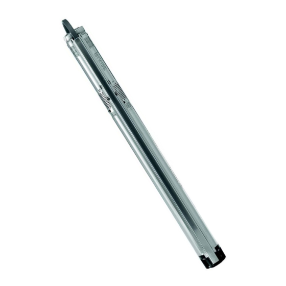
Section 1: System Description The Geoflo 3 is a three inch diameter deep well submersible pump mainly designed for the pumping of raw water in domestic water supply. This manual is designed to assist in the proper set-up, installation, and operation of these pumps. -
Page 6: Section 2: System Installation
CAUTION: This pump has been approved for pumping water of a maximum 86°F only. Liquid Temperatures/Cooling Figure 2-1 shows a Geoflo 3 pump installed in a well. With the pump operating, it illustrates the following: Well diameter ... - Page 7 Figure 2-1: Pump Inside Well Motor Preparation Geoflo 3 submersible motors have water-lubricated slide bearings. No additional lubrication is required. The submersible motors are factory-filled with a special motor liquid, type SML 2 or SML 3, which will protect the motor liquid down to 4°F and prevent...
-
Page 8: Installation
the growth of bacteria. The level of motor liquid is important for the operating life of the bearings and consequently the life of the motor. Refilling of Motor Liquid If for any reason the motor liquid has been drained or lost, the motor must be refilled with Geoflo motor liquid SML 2 or SML 3. -
Page 9: Installing The Pump
Installing the Pump Installation Depth The dynamic water level should always be above the pump, see Figure 2-4. A = Dynamic water level B = Static water level C = Minimum 3 inch well diameter D = Drawdown E = Installation depth below static water level. - Page 10 Installation Depths Maximum installation depth: 500 feet below the static water level. Minimum installation depth: 1.75 feet below the dynamic water level. Vertical Installation During start-up and operation, the pump must always be completely submerged in water. Horizontal Installation The pump must be installed at least 1.75 feet below the dynamic water level. If there is a risk that the pump might be covered by mud, the pump must always be placed in a flow sleeve.
-
Page 11: Section 3: System Operation And Assembly
The current consumption can only be measured accurately by means of a true RMS instrument. If other instruments are used, the value measured will differ from the actual value. The Geoflo 3 pumps can be connected to a CU 300 control box. Motor Protection The motor has built-in automatic thermal overload protection and requires no additional motor protection. - Page 12 WARNING: Reduced risk of electric shock during operation of this pump requires the provision of acceptable grounding. If the means of connection to the supply connected box is other than grounded metal conduit, ground the pump back to the service by connecting a copper conductor, at least the size of the circuit conductors supplying the pump.
-
Page 13: Cable Sizing
Note: The values apply to 230 V, 60 Hz, and conform to the requirements stated in the National Electrical Code Book. Note: Recommended maximum cable length between the Geoflo 3 and the CU 300 control box = 650 ft. Splicing the Cable The submersible drop cable can be ordered separately in lengths of 25 to 300 ft., see... -
Page 14: Piping
Figure 3-5: Gripping the Pump Generator Operation It is safe to operate the Geoflo 3 with a generator. The generator must be sized 50% above the P1 (input power) values of the pump. See the following table. Motor... - Page 15 Switch off the electricity supply for 1 minute. Geoflo 3 Motors NOTE: All Geoflo 3 motors are factory-set to detect dry-running conditions. However, if the maximum pump speed setting is changed, the dry-running stop value must also be changed. Please refer to CU 300...
-
Page 16: Assembly Of Pump And Motor
Assembly of Pump and Motor To assemble pump end and motor, proceed as follows: Place the motor horizontally in a vice and tighten it, see fig. 3-7. Pull the pump shaft out to the position shown in fig. 3-6. Grease the motor shaft end with the grease supplied with the motor. Screw the pump end on the motor (55 Nm). -
Page 17: Section 4: System Maintenance
Section 4: System Maintenance The pumps are normally maintenance-free. Deposits and wear may occur. For that purpose, service kits and service tools are available from Geotech. The pumps can be serviced at a Geotech service center. -
Page 18: Section 5: System Troubleshooting
Section 5: System Troubleshooting Fault Cause Remedy 1. The pump does a) The fuses are blown. Replace the blown fuses. If the not run. new fuses blow too, check the electrical installation and the drop cable. b) The GFI circuit breaker has Reset the circuit breaker. -
Page 19: Instruments Not Allowed
4. Frequent starts a) The differential of the Increase the differential. and stops. pressure switch between the However, the stop pressure start and stop pressures is must not exceed the operating too small. pressure of the pressure tank and the start pressure should be high enough to ensure sufficient water supply. -
Page 20: Checking Of Motor And Cable
Checking of Motor and Cable 1. Supply voltage Measure the voltage L1 The voltage should, when the (RMS) between phase and motor is loaded, be within the range specified under Electrical Connection in Connect the voltmeter to Section 3: System Operation the terminals at the and Assembly. -
Page 21: Section 6: System Specifications
Section 6: System Specifications Technical Data Supply voltage Storage conditions 1 x 100-115 V, 50/60 Hz, PE. Minimum ambient temperature: 4°F. 1 x 200-240 V, 50/60 Hz, PE. Maximum ambient temperature: 140°F. Operation via generator Freeze protection Recommended generator output must Note: The motor must not be stored be equal to P1 [kW] + 50% and without being filled with motor liquid. -
Page 22: Disposal
Disposal This product or parts of it must be disposed of in an environmentally sound way: Use the public or private waste collection service If this is not possible, contact Geotech. -
Page 23: Section 7: Parts And Accessories
Section 7: Parts and Accessories Pumps Part Number Description 86750100 PUMP,GEOFLO3,5S05-90,115V 86750101 PUMP,GEOFLO3,5S05-90,240V 86750102 PUMP,GEOFLO3,5S05-140,115V 86750103 PUMP,GEOFLO3,5S05-140,240V 86750104 PUMP,GEOFLO3,5S05-180,115V 86750105 PUMP,GEOFLO3,5S05-180-,240V 86750106 PUMP,GEOFLO3,5S07-230,240V 86750107 PUMP,GEOFLO3,5S07-270,240V 86750108 PUMP,GEOFLO3,5S07-320,240V 86750109 PUMP,GEOFLO3,5S10-360,240V 86750110 PUMP,GEOFLO3,5S10-410,240V 86750111 PUMP,GEOFLO3,5S15-450,240V 86750112 PUMP,GEOFLO3,10S05-110,115V 86750113 PUMP,GEOFLO3,10S05-110,240V 86750114 PUMP,GEOFLO3,10S05-160,115V 86750115 PUMP,GEOFLO3,10S05-160,240V 86750116 PUMP,GEOFLO3,10S07-200,240V... -
Page 24: Jacketed Tefzel Motor Leads
11200183 STATUS BOX, GEOFLO3 CU300 11200950 MODULE,GO REMOTE, BLUETOOTH SHROUD,COOLING,SS,3”,4.25” OD 11200251 TANKFULL PROBE, 25’ 2390073 TANKFULL PROBE, 50’ 2390069 82350002 GEOTECH SITEPRO TELEMETRY 12350067 SITEVIEW REMOTE SYSTEM CONTROL 11200370 POTENTIOMETER, GEOFLO3 81200030 CU300 STATUS BOX 81200058 CU300 STATUS BOX+POTENTIOMETER... - Page 25 Revision History Project # Description Date Created Geotech Manual – AH D2305 10/5/2023...
- Page 26 NOTES...
-
Page 27: The Warranty
Geotech agrees to repair or replace, at Geotech’s option, the portion proving defective, or at our option to refund the purchase price thereof. Geotech will have no warranty obligation if the product is subjected to abnormal operating conditions, accident, abuse, misuse, unauthorized modification, alteration, repair, or replacement of wear parts. - Page 28 Geotech Environmental Equipment, Inc. 2650 East 40th Avenue Denver, Colorado 80205 (303) 320-4764 ● (800) 833-7958 ● FAX (303) 322-7242 email: sales@geotechenv.com website: www.geotechenv.com...
Need help?
Do you have a question about the Geoflo 3 and is the answer not in the manual?
Questions and answers