Table of Contents
Advertisement
Quick Links
Advertisement
Table of Contents

Related Manuals for Geotech Guzzler


Summary of Contents for Geotech Guzzler
- Page 1 Geotech Guzzler Installation and Operation Manual Rev 07/31/2018 Part #16600169...
-
Page 3: Table Of Contents
Quarterly Maintenance ....................14 Cleaning the Skimmer and Intake Screen..............15 Air Regulator Maintenance ..................15 Servicing the Guzzler Pump and Control Box .............. 15 Section 6: System Troubleshooting ................16 Section 7: System Specifications ................. 19 Tubing Information ....................... 21 System Schematics ..................... -
Page 4: Documentation Conventions
DOCUMENTATION CONVENTIONS This manual uses the following conventions to present information: An exclamation point icon indicates a WARNING of a situation or condition that could lead to personal injury or death. You should not proceed until you read and thoroughly understand the WARNING message. -
Page 5: Section 1: System Description
The Guzzler’s Dual Diaphragm Pump creates a vacuum, drawing product from the down well intake and discharges it into a recovery tank (not included with system). The Guzzler requires 6 SCFM (.17 SCMM) minimum of air pressure at 45 PSI (3 bar) in order to operate. -
Page 6: Section 2: System Components
Operating Manual for the pump. Air Regulator Each Guzzler includes a built-in Air Regulator with a filter and pressure gauge, and an AIR ON/OFF switch. The Air Regulator controls operating pressure, removes particles and liquids in the air stream, and has an automatic drain plumbed to the bottom of the control box. -
Page 7: Down Well Intakes: Skimmers And Total Fluids
Skimmer shaft to protect the intake float and to allow unobstructed travel within the well. Standard Skimmers can provide 12” (30 cm) to 24” (61 cm) of intake travel. Geotech can provide up to an extended 5’ (1.5 m) of travel (4” Skimmers only) on a custom order basis. - Page 8 Heavy Oil Skimmer Attachment The optional Heavy Oil Skimmer attachment is designed to recover a range of fluids from gasoline to gear oil, skimming the product down to .01’ (3 mm) in 4” (10 cm) diameter and larger wells. This option is best suited when the viscosity of the hydrocarbon is greater than the capability of the filter screen technology (screen can no longer pass the hydrocarbon fluid).
- Page 9 High Temperature, Heavy Oil Skimmer Attachment For high temperature well environments, Geotech provides a High Temperature, Heavy Oil (HTHO) Skimmer that incorporates an ultra-high molecular weight (UHMW) polyethylene intake buoy. The HTHO Skimmer has stainless steel end caps placed at the top and bottom of a stainless steel screen to keep out debris.
- Page 10 The Total Fluids System consists of a Level Control Valve, a Total Fluids Intake, and 50’ of sensor airline. The Level Control Valve is mounted directly onto the Guzzler Control Box at the AIR SUPPLY INPUT quick connect. Figure 2-5 shows an example of how the Total Fluids System connects to the Guzzler.
- Page 11 The Tankfull Shut-off Sensor assembly consists of a PVC or Stainless Steel sensor installed to a 2” NPT bung opening in a recovery tank and connects to the Guzzler Control Box’s TANKFULL SHUTOFF input with a 1/4” OD sensor airline. The recovery tank with the Tankfull Shut-off Sensor tube installed must be within 50’...
-
Page 12: Accessories
Bottled air may be used to operate the Guzzler if operating an air compressor is not feasible. A high-pressure regulator must be used to reduce the air pressure to the range of 45 PSI (.06 bar) to 100 PSI (7 bar). -
Page 13: Section 3: System Installation
Section 3: System Installation Planning Guidelines To install the Guzzler, use the following guidelines to determine a suitable location for the air compressor, Guzzler Control Box, down well intakes, and product recovery tank. The Standard Guzzler does not include an air source. The air source/compressor must supply 6 CFM (170 LFM) at 45 PSI (bar) minimum. -
Page 14: Installation
When the fluid level reaches approximately 11” (28 cm) on the sensor tube side, the Tankfull Shut-off Valve will activate to shut off the pump. Attach tubing from Tankfull Shut-off Sensor tube to the Guzzler Control Box tube connector labeled TANKFULL SENSOR. -
Page 15: Section 4: System Operation
Allow 20 seconds for the pump to prime before adjusting to desired air pressure, recommended 45 PSI/3 bar. The Guzzler requires only compressed air to operate. All units will be sent with the AIR ON/OFF switch in the OFF position. Required pressure will vary depending on site conditions. -
Page 16: Section 5: System Maintenance
Section 5: System Maintenance The Guzzler requires very little maintenance. With proper installation, and by following periodic maintenance procedures, operation of the system will remain efficient and trouble free. In cold climates where the temperatures may fall below freezing, the air supply should be run through an air dryer to prevent the pump from stalling. -
Page 17: Cleaning The Skimmer And Intake Screen
Blow air through filter element from inside to outside to remove surface contaminants. Inspect parts. Replace any parts that are damaged. 10. Reassemble the Air Regulator. Servicing the Guzzler Pump and Control Box To service the Guzzler Control Box, contact Geotech at 1-800-833-7958. -
Page 18: Section 6: System Troubleshooting
Section 6: System Troubleshooting Problem: The Guzzler operates but recovers no product. Solutions: Product has been removed. Decrease the pumping rate/pressure to conserve air. Pump is operating too fast, pumping rate exceeds product recharge rate. Decrease the pumping rate. - Page 19 Solutions: The viscosity of the product is too thick for the Skimmer. Contact Geotech to discuss other Skimmer options for the type of product in the well. The intake screen is obstructed or the coiled hose is kinked. ...
- Page 20 Check Level Control Valve plumbing for air leaks. All seals must be tight. Breather vent may exhaust small amounts of air. If there are no noticeable leaks, contact Geotech. If these troubleshooting guidelines have not resolved the problem, then contact Geotech at 1-800-833-7958.
-
Page 21: Section 7: System Specifications
Materials: PVC, Stainless Steel, Brass, Rubber Process Connections: To Guzzler Control Box: 1/4" OD Tube, Poly-Tite Compression Fitting To recovery tank: 2” NPT Bung on sensing tube Maximum 1/4” OD tubing length from Sensor to Guzzler Control Box: 50’ (15.2 m) - Page 22 2” Skimmer Assembly Size: 35.5” L x 1.75” OD (90 cm L x 4.5 cm OD) Weight: 1.8 lbs. (0.8 kg) Materials: 304 SS, Polyethylene, PVC, Polypropylene, and Brass Fittings Effective Travel: 12” (30.5 cm) Standard Travel Operating Temperature: 32º to 100º F (0° to 38° C) Minimum fluid level to activate Skimmer = 15”...
-
Page 23: Tubing Information
Tubing Information FEP tubing ASTM 3296; Chemically Inert to most industrial fluids and gasses; UL 94 V-0; FDA Compliant Material: Virgin/Recycled Blend Chemical resistance: Excellent Weather Resistance: ASTM Method: Florida Exposure. No significant change in tensile strength; slight increase in elongation, but still high after 25 years. -
Page 24: System Schematics
System Schematics Figure 7-1: Guzzler Hydrocarbon Recovery Schematic... - Page 25 Figure 7-2: Guzzler Total Fluids Schematic...
-
Page 26: Section 8: Replacement Parts List
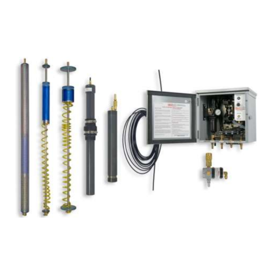
Section 8: Replacement Parts List Guzzler Components Figure 8-1: Guzzler System... -
Page 27: Guzzler Components List
VENT, BREATHER, 1/4" NPT 11150252 GUZZLER, INTAKE,TOTAL FLUIDS,W/ LVL CNTRL 56600093 SNSR,50’1/4”TUBING GUZZLER, LVL CNTRL SNSR ONLY,TOTAL FLUIDS,UPPER 56600092 GUZZLER, INTAKE ONLY, LVL CNTRL, TOTAL FLUIDS, LOWER 56600091 TUBING,NYL,1/4ODX.040"W,BLK 16600039 GUZZLER, INTAKE ONLY, LVL CNTRL, TOTAL FLUIDS, LOWER 56600091 TUBE,CONN,1/4x1/8MPT,POLYTITE PUMP 16600037 HOSEBARB, BRS,3/8”x1/8MPT... - Page 28 Additional Intake Options ASSY, INTAKE, 166, DROP TUBE, WITH 3/8" HOSEBARB 51150138 Remediation Accessories MANUAL,TEST KIT,HYDROCARBON VISCOSITY 26030020 TEST KIT,HYDROCARBON VISCOSITY 86020001...
- Page 29 Down Well Skimmers Figure 8-2: Standard 2” Skimmer Assembly...
- Page 30 2” Skimmer Assembly 100-mesh (56600003) and 60-mesh (56600069) Item # Part Description Part # CLAMP,SS,STEPLESS EAR,7MM 16600005 HOSE,COILED,PR2 26650304 HOSEBARB,BRS,3/8"X1/8FPT 16650308 CENTRALIZER,PVC,SKIMMER,2" 26650306 SHAFT,SS,SKIMMER,33.5",PRC 26600002 CAP,BRS,1/8FPTx10-32 90 DEG 16600064 HOSEBARB,BRS,1/8"X10-32,90DEG 17500149 ASSY,BUOY,SKIMMER,2"100MESH 56650309 ASSY,BUOY,SKIMMER,2" 60 MESH 56650312 HOSE CLIP,SKIMMER FLOAT 26650028 2"...
- Page 31 Figure 8-3: Standard 4” Skimmer Assembly, extended options available...
- Page 32 4” Skimmer Assembly 100-mesh (56600004) and 60-mesh (56600070) Item # Part Description Part # CLAMP,SS,STEPLESS EAR,7MM 16600005 HOSE,COILED,PR4 16650312 HOSEBARB,BRS,3/8"X1/8FPT 16650308 CENTRALIZER,SKIMMER,PR4 16600048 SHAFT,SS,SKIMMER,33.5",PRC 26600002 CAP,BRS,1/8FPTx10-32 90 DEG 16600064 HOSEBARB,BRS,1/8"X10-32,90DEG 17500149 ASSY,BUOY,SKIMMER,4"100 MESH 56650310 ASSY,BUOY,SKIMMER,4" 60 MESH 56650313 HOSE CLIP,SKIMMER FLOAT 26650028 4"...
- Page 33 Figure 8-4: 4” Heavy Oil Skimmer Assembly...
- Page 34 4” Heavy Oil Skimmer (56600005) Item # Part Description Part # BUOY,PP,HEAVY OIL 26600004 FTG,INTAKE,OIL BOUY 26600005 HOSEBARB,BRS,.170"X1/8MPT,90D 17500148 HOSEBARB,BRS,3/8"X1/8FPT 16650308 CENTRALIZER,SKIMMER,PR4 16600048 SHAFT,SS,OIL SKIMMER,38" 26600006 HOSE,COILED,OIL SKIMMER 26600007 CLAMP,SS,DBL PINCH,9/32-23/64" 11200273 COUPLING,SS4,.125" 16600006 4" Heavy Oil Skimmer Options ASSY,BUOY,OIL SKIMMER,4" 56600060 VALVE, CHECK, PRODUCT DISCHARGE 26600157...
- Page 35 Figure 8-5: 4” High Temperature, Heavy Oil Skimmer Assembly...
-
Page 36: 4", High Temp, Heavy Oil Skimmer With Screen (56600012)
4”, High Temp, Heavy Oil Skimmer with Screen (56600012) Item # Part Description Part # BUOY,UHMW,HEAVY OIL,HI-TEMP 26600206 FITTING,BUOY INTAKE,HTHO 26600207 HOSEBARB,BRS,1/8"X10-32,90DEG 17500149 HOSEBARB,EXT,1/8M/F NPT,10-32 27200012 END CAP,BUOY INTAKE,HTHO 26600209 TUBING, COILED, PTFE, HTHO 56600074 SKIMMER,SHROUD,4",HTHO 26600210 PIPE,CENTERING,SCH80,1/8",HTHO 27500005 FITTING,HEX CAP,1/8FPT,HTHO 27200013 Additional 4"... - Page 37 EDCF# DESCRIPTION REV/DATE Previous Release 11/02/2011 Project Updated manual to reflect standard pump - DD 03/25/2014 #1369 Project Updated with tubing information – DD 06/03/2014 #1369 Project Combined Total Fluid System, updated Guzzler 4/18/2017 #1427 Design and Operation, StellaR, SB...
- Page 38 NOTES...
- Page 39 NOTES...
-
Page 40: The Warranty
Geotech agrees to repair or replace, at Geotech’s option, the portion proving defective, or at our option to refund the purchase price thereof. Geotech will have no warranty obligation if the product is subjected to abnormal operating conditions, accident, abuse, misuse, unauthorized modification, alteration, repair, or replacement of wear parts. - Page 41 Geotech Environmental Equipment, Inc. 2650 East 40th Avenue Denver, Colorado 80205 (303) 320-4764 ● (800) 833-7958 ● FAX (303) 322-7242 email: sales@geotechenv.com website: www.geotechenv.com...
Need help?
Do you have a question about the Guzzler and is the answer not in the manual?
Questions and answers