Table of Contents
Advertisement
Quick Links
Advertisement
Table of Contents
Troubleshooting

Related Manuals for Dormakaba RAC5 MFC


Summary of Contents for Dormakaba RAC5 MFC
- Page 1 RAC5 Installation Guide PK3738- 06/2023 Original document...
-
Page 2: Table Of Contents
7 Annex C: Electromagnetic Interference ..........18 8 Annex D: RAC5 MFC Components ............19 9 Annex E: Single Reader Wiring ............. 20 10 Annex F: Dual Reader Wiring ............... 21 06-2023 dormakaba Canada Inc. RAC5 MFC Installation Guide – PK3738 | 1... - Page 3 11 Annex G: RAC5 MFC Wall Reader Mounting Instructions ....22 11 Annex H: Access Override Panel Wiring ..........31 12 Annex I: Reader Drilling Templates ............ 32 06-2023 dormakaba Canada Inc. RAC5 MFC Installation Guide – PK3738 | 2...
-
Page 4: Introduction And Disclaimers
Do not connect to a receptacle controlled by a switch. If installing the RAC5 MFC in an elevator cage environment, or in proximity to any other equipment that may generate high levels of electromagnetic interference, follow the installation requirements as indicated in Annex C to prevent any operational instability. -
Page 5: Safety Procedures
This device complies with Part 15 of the FCC Rules. Operation is subject to the following two conditions: (1) This device may not cause harmful interference, and (2) This device must accept any interference received, including interference that may cause undesired operation. 06-2023 dormakaba Canada Inc. RAC5 MFC Installation Guide – PK3738 | 4... -
Page 6: Product Description
For surface mount, the surface area required for the contactless reader is 2 7/8" L (73mm) x 1 7/8" W (47.7mm) x 2" D (50.8mm), 2" depth behind panel required. The RAC5 MFC is an access control solution that can operate 2 individual card readers, provides multiple relays, and much more as per the feature list below. -
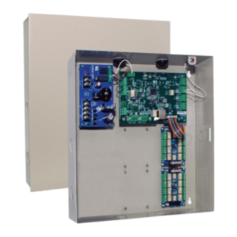
Page 7: Components
Power Supply: Provides the DC power required for operation of the controller PCB and all peripherals Controller Board: Controls all the features of the RAC5 MFC system Tamper Switch: Attached to the RAC5 MFC enclosure to generate an alarm if the box is opened during operation Power &... -
Page 8: Contactless Card Reader
3.1.3 Cables (not shown) NOTE: All items come factory installed. System cables: Power supply to LEDs, controller PCB and controller PCB jumpers 3.1.4 Card Reader(s) Contactless Reader Options (see Figure 3) 06-2023 dormakaba Canada Inc. RAC5 MFC Installation Guide – PK3738 | 7... -
Page 9: Power Adapter
Philips screwdriver - #2 • Slotted screwdriver • Adjustable wrenches • Crimp tool 18-22 AWG • Pliers • Wire cutter/stripper • Hammer or rubber mallet • Awl or center punch 06-2023 dormakaba Canada Inc. RAC5 MFC Installation Guide – PK3738 | 8... -
Page 10: Exploded View
Ensure all components ordered and materials/tools required are available • Ensure all cabling is available for the peripherals/components being installed All installations and wiring of RAC5 MFC enclosure & peripherals must comply with all IMPORTANT applicable local building codes and regulations and National Electric Code, ANSI/NFPA 70. -
Page 11: Pre-Installation Procedures
2. Identify location(s) for contactless readers. • Card readers must be placed within 1,000 feet (300 m) from the RAC5 MFC enclosure • Readers should be installed in an obvious location at an ergonomic height near the access door or elevator being controlled •... -
Page 12: Installation And Wiring Procedures
IMPORTANT is closed, the switch itself is also in a closed state. Ensure that the wiring to the premise alarm system is done accordingly to prevent false alarms. 06-2023 dormakaba Canada Inc. RAC5 MFC Installation Guide – PK3738 | 11... - Page 13 Up to 8 expansion boards can be used for total control of 64 floors (secure stops). The relay outputs are at the wiring input of each three-terminal connector (1, C, 3) on the expansion PCB as well as being 06-2023 dormakaba Canada Inc. RAC5 MFC Installation Guide – PK3738 | 12...
- Page 14 Several floors can be controlled by one relay (one secure stop). The relays in the RAC5 MFC are UL rated and are capable of a maximum switching of 30 VDC @ 1A. For time duration of relay state see Ambiance System Settings, under Security and Lock Access.
- Page 15 8. Complete the installation. a) If the access door was removed, reinstall the door to the RAC5 MFC enclosure b) Bend the two tabs on the door to a maximum of 30 degrees as shown in Figure 7 Figure 7...
-
Page 16: Annex A: Quick Troubleshooting Guide
Annex B, Figure 8 5.2 Card Reading Troubleshooting Symptom Action • Verify that the RAC5 MFC controller is active. If not, restart the RAC5 MFC controller: Press the Reset Switch (SW1) or disconnect and No feedback on Reader when reconnect the power •... -
Page 17: External Inputs Troubleshooting
Tamper Switch 5.4 Relay Expansion Board Troubleshooting The power for the RAC5 MFC must be turned off before connecting or disconnecting the CAUTION Relay Expansion Board or if changing the relay output state using Switch 4. If Switch 4 is set to RELAYS OFF, LEDs on the Relay Expansion board should be normally OFF in idle state. -
Page 18: Annex B: Multi-Floor Controller Rac5 Mfc
If SW4 is in the ON position when the bypass switches (SW1 and SW3) are "OFF", then GREEN LEDs are "ON" & Controller Board Test Mode (SW4) ON - Test mode can activate the relays operation dormakaba Canada Inc. - PK3745 06-2023 dormakaba Canada Inc. RAC5 MFC Installation Guide – PK3738 | 17... -
Page 19: Annex C: Electromagnetic Interference
7 Annex C: Electromagnetic Interference As per any other electronic equipment, the RAC5 MFC can be affected by electromagnetic interference cause by industrial electrical equipment such as elevator motors. To prevent the unit from operational instability, lded cables should be used and connections made as per the diagram below. -
Page 20: Annex D: Rac5 Mfc Components
IMPEDANCE OF CABLE TO BE 100 OHMS. MAXIMUM LENGTH OF CABLE IS 1000 FT. NORTH AMERICAN POWER ADAPTER 062/511929R INTERNATIONAL POWER ADAPTER 126-515160-1 RING TERMINAL SURFACE MOUNT FLUSH MOUNT ROUND READER 06-2023 dormakaba Canada Inc. RAC5 MFC Installation Guide – PK3738 | 19... -
Page 21: Annex E: Single Reader Wiring
J12 pin 4 J5 TXM Wire connection to back of contactless card reader J4 - (BLACK), J4 + (RED), J5 TXP (WHITE), J5 TXM (GREEN) CONTACTLESS RFID WALL MOUNTED READER 06-2023 dormakaba Canada Inc. RAC5 MFC Installation Guide – PK3738 | 20... -
Page 22: Annex F: Dual Reader Wiring
J12 pin 4 J5 TXM Wire connection to back of contactless card reader J4 - (BLACK), J4 + (RED), J5 TXP (WHITE), J5 TXM (GREEN) CONTACTLESS RFID WALL MOUNTED READER 06-2023 dormakaba Canada Inc. RAC5 MFC Installation Guide – PK3738 | 21... - Page 23 Wear Safety glasses while preparing wall. Introduction The RFID wall mounted reader provided by dormakaba is compact, lightweight, rugged and water resistant, able to withstand temperatures from -30°F to 150°F (-35°C to 66°C). It is made from durable materials and comes with at least 15 feet (4.6 m) of cable.
- Page 24 5. Hook the top of the reader enclosure (item #2) onto the top of the mounting plate (item #4) and secure together with the included screw (item #1), tightened at the bottom of the reader 06-2023 dormakaba Canada Inc. RAC5 MFC Installation Guide – PK3738 | 23...
- Page 25 2. Install reader (item #2) then faceplate (item #5) into the panel using the screws (item #4) and nuts (item 3. Connect cables for RAC5 as per Annex E and F 06-2023 dormakaba Canada Inc. RAC5 MFC Installation Guide – PK3738 | 24...
- Page 26 6. Re-assemble items #1 through #5 in order as shown in Figure 15 etail , then assemble to gang box (item #6) and tighten screws making sure the reader face protrudes past the faceplate as shown in Figure 15 C 06-2023 dormakaba Canada Inc. RAC5 MFC Installation Guide – PK3738 | 25...
- Page 27 5. Connect cables for RAC5 as per Annex E and F 6. Re-connect BLE cable (item #6) 7. Re-assemble reader (item #2) to assembly and secure with screw (item #1) 06-2023 dormakaba Canada Inc. RAC5 MFC Installation Guide – PK3738 | 26...
- Page 28 6. Assemble to panel using provided 6-32 hex screws, lock nuts, and washers. Ensure there is no washer under 2 8-32 reader assembly screws when using double gang plate 06-2023 dormakaba Canada Inc. RAC5 MFC Installation Guide – PK3738 | 27...
- Page 29 4. Connect cables for RAC5 as per Annex E and F 5. Connect BLE cable (item#6) to BLE connector (Figure 18 C) 6. Re-assemble reader (item #2) assuring that the screw (item #1) is at the bottom 06-2023 dormakaba Canada Inc. RAC5 MFC Installation Guide – PK3738 | 28...
- Page 30 5. Connect cables for RAC5 as per Annex E and F 6. Connect BLE cable (item #6) to BLE connector (Figure 19 B) 7. Re-assemble reader (item #2) assuring that the BLE connector is at the bottom 06-2023 dormakaba Canada Inc. RAC5 MFC Installation Guide – PK3738 | 29...
- Page 31 3. Connect BLE module to the reader connector as shown 4. Install BLE bracket under 2 #4 screws 5. Tighten #4 screws 6. Re-install reader to panel using previously removed hardware 06-2023 dormakaba Canada Inc. RAC5 MFC Installation Guide – PK3738 | 30...
- Page 32 RD#2 Note 1: The input from the Access Override Panel must be connected to a Normally Closed Dry contact. When the RAC5 MFC Access Override is activated, power to all relays will be removed. Ensure you have configured Switch 4 of the Relay Expansion Board appropriately for your desired controller behavior.
- Page 33 12 Annex I: Reader Drilling Templates Reader Drilling Templates (not to scale) SURFACE MOUNT PREP SURFACE MOUNT READER FLUSH MOUNT PREP FLUSH MOUNT READER WITH TRIM PLATE 06-2023 dormakaba Canada Inc. RAC5 MFC Installation Guide – PK3738 | 32...
- Page 34 ROUND READER FOR DIRECT PANEL MOUNT PREP ROUND READER WITH TRIM PLATE REMOVED ROUND READER WITH TRIM PLATE ROUND READER WITH TRIM PLATE PREP 06-2023 dormakaba Canada Inc. RAC5 MFC Installation Guide – PK3738 | 33...
- Page 35 Mechanical Lodging Key Systems Systems Entrance Interior Glass Systems Systems Safe Service Locks dormakaba dormakaba Canada 6161 E. 75th Street 7301 Decarie Blvd. Indianapolis, IN 46250 Montreal Quebec H4P 2G7 T: 800 999 6213 T: 800 999 6213 dormakaba.us dormakaba.com...
Need help?
Do you have a question about the RAC5 MFC and is the answer not in the manual?
Questions and answers