Table of Contents
Advertisement
Quick Links
Advertisement
Table of Contents
Troubleshooting

Related Manuals for Dormakaba RAC5 Lite


Summary of Contents for Dormakaba RAC5 Lite
- Page 1 RAC5 Lite Installation Guide...
-
Page 2: Table Of Contents
4.2.2 Mount the Contactless Card Reader ................. 4.2.3 Connect Peripheral Wiring ..........4.2.3.1 Electric Strike or Electromagnetic Lock (Locking Device) ................4.2.3.2 Request to Exit Button (REX) ..................4.2.3.3 Remote Unlock Button 12-2020 dormakaba Canada Inc. RAC5 Lite Installation Guide – PK3736 | 1... - Page 3 ................9.2 Card Reading Troubleshooting ................9.3 External Inputs Troubleshooting ................9.4 Locking Device Troubleshooting ............9.5 Programming and Auditing Troubleshooting 10 Annex E: Reader Drilling Template ............12-2020 dormakaba Canada Inc. RAC5 Lite Installation Guide – PK3736 | 2...
-
Page 4: Introduction And Disclaimers
Do not connect to a receptacle controlled by a switch. If installing the RAC5 LITE in an elevator cage environment, or in proximity to any other equipment that may generate high levels of electromagnetic interference, follow the installation requirements as indicated in Annex C to prevent any operational instability. -
Page 5: Safety Procedures
This device complies with Part 15 of the FCC Rules. Operation is subject to the following two conditions: (1) This device may not cause harmful interference, and (2) This device must accept any interference received, including interference that may cause undesired operation. 12-2020 dormakaba Canada Inc. RAC5 Lite Installation Guide – PK3736 | 4... -
Page 6: Product Description
The Contactless Card Reader mounts directly on doorframes as narrow as 2 inches (5.1 cm), while the insert card reader can only be installed in an elevator panel. The RAC5 Lite is a simple access control solution for a dual-card reader, providing features as per the feature list below. See Figure 1 for a typical configuration. -
Page 7: Components
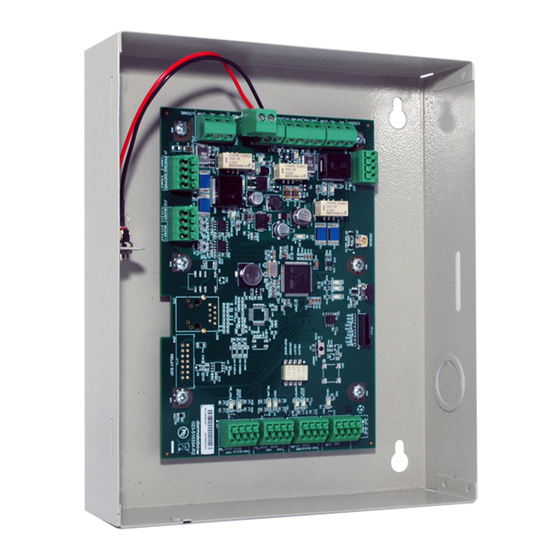
2.2.1 Controller Box Figure 3 – RAC5 Lite Controller Box RAC5 Lite Enclosure & Access Door: Holds the controller board (PCB) and the power adapter jack. Knockouts are available on 3 sides for routing of peripheral cables Controller Board (PCB): Controls all the features of the RAC5 Lite system... -
Page 8: Contactless Card Reader
Figure 4 – Contactless Card Reader 2.2.3 Locking Devices The RAC5 Lite controller PCB provides a single relay output that can be used to control an Electric Strike (G) or Electromagnetic Lock (H) as shown in Figure 5. Figure 5 – Electric Strike & Electromagnetic Lock 2.2.3 Optional Peripherals... -
Page 9: Checklist And Exploded Views
AC outlet prongs. Input power requirements of 220-240 VAC, 50-60 Hz 3.1.6 Other Peripherals (optional) Request to Exit button Remote Programming Interface (RPI) [not shown] Remote Unlock (not shown) 12-2020 dormakaba Canada Inc. RAC5 Lite Installation Guide – PK3736 | 8... -
Page 10: Programming Device
3.1.7 Programming Device NOTE: Purchased separately. Programming of the RAC5 Lite can only be done with the M-Unit. IMPORTANT 3.1.8 Installation Hardware Bag 4x Philips wood screw, #8 x 1-1/4” 4x Nylon anchor, #6-10 4x Concrete anchor, #7-9 1x Strain relief connector with locking nut... -
Page 11: Exploded View
Do not connect power to the enclosure until the end of the installation process. If installing CAUTION the RAC5 Lite in an elevator cage environment, or in proximity to any other equipment that may generate high levels of electromagnetic interference, follow the installation requirements as indicated in Annex C to prevent any operational instability. -
Page 12: Pre-Installation Procedures
Access to the RAC5 Lite enclosure must be restricted to authorized personnel • AC power must be available within 6 feet (1.8 m) of the RAC5 Lite enclosure • The location temperature must be from 0 to 49 °C (32 to 120 °F) and sheltered against weather hazards and dripping water with relative humidity conditions less than 85% at 32 °C (90 °F) -
Page 13: Installation And Wiring Procedures
Install the enclosure in the desired location using the appropriate items from the hardware bag. NOTE: For easier access, we recommend removing the access door prior to installation Figure 8 – Enclosure 12-2020 dormakaba Canada Inc. RAC5 Lite Installation Guide – PK3736 | 12... -
Page 14: Mount The Contactless Card Reader
Every wire must pass through the strain relief as connected in the pre-installation IMPORTANT procedures. Follow the indications below for the different peripherals being connected. The actual items to connect will vary based on the system configuration ordered. 12-2020 dormakaba Canada Inc. RAC5 Lite Installation Guide – PK3736 | 13... -
Page 15: Electric Strike Or Electromagnetic Lock (Locking Device)
4.2.3.1 Electric Strike or Electromagnetic Lock (Locking Device) Refer to Annex B for detailed wiring. dormakaba Canada Inc. does not provide technical or field support for third party locking IMPORTANT devices. Please consult the device manufacturer for support. The following table indicates the maximum recommended wire length that can be used for typical locking devices, based on wire gauge. -
Page 16: Motion Detector
4.2.4 Install Strain Relief Bushing (For Power Adapter Only) One strain relief bushing is provided in the hardware bag to secure the power adapter cable leading into the RAC5 Lite enclosure to help prevent the possibility of wire tampering. Figure 9 – Enclosure Remove the keyhole knock-out on from the inner side of the enclosure using a hammer and screwdriver or awl to tap out the small metal disc. -
Page 17: Complete The Installation
8. If the RAC5 Lite is connected to a Fire Panel and the electromagnetic lock powered by the 12 VDC output of the RAC5 Lite, verify that the electromagnetic lock or a fail-safe electric strike is deactivated when the Fire Alarm is active (open input). -
Page 18: Power Failure
CAUTION The maximum recommended load for the output relay in the RAC5 Lite system is 1 Amp at 30 VDC. The current supplies by the controller PCB for each locking device used is 0.64 Amps from connector J18, pin 1 and J6, pin 1. -
Page 19: Annex A: Wiring Diagram And Tables
Wire connection to back of contactless card reader J11 pin 2 TB-1 (BLACK), TB-2 (RED), TB-3 (WHITE), TB-4 (GREEN) REX2 J3 pin 1 Request to Exit #2 J3 pin 2 12-2020 dormakaba Canada Inc. RAC5 Lite Installation Guide – PK3736 | 18... -
Page 20: Annex B: Peripheral Wiring Diagrams
PWR GND GND PWR READE R 2 READE R 1 1 (+) 2 (-) 3 (+) 4 (-) RD#1 RD#2 Green Black White Maximum cable length of 1000 Feet 12-2020 dormakaba Canada Inc. RAC5 Lite Installation Guide – PK3736 | 19... - Page 21 Bypass wire and connect J18 to the Fire Alarm panel as per Fire Alarm Panel Wiring diagram (see Annex B, Figure 10). In this case the Electric Strike MUST be powered from the RAC5 Lite’s +12V output as shown in this diagram.
- Page 22 Locking Device Note: If the locking device is inductive (such as a strike) place a diode across the locking device’s terminals as shown in the strike wiring diagrams. 12-2020 dormakaba Canada Inc. RAC5 Lite Installation Guide – PK3736 | 21...
- Page 23 1 (+) 2 (-) 3 (+) 4 (-) RD#1 RD#2 Power Supply NOTE: If the second reader is not used on RAC5 Lite, the motion detector can be powered from J1, pin 3 (12V) Motion and 4 (GND). Detector 12-2020...
- Page 24 Normally Closed dry contact output. Note 2: If the Fire Alarm Panel connection is not required, place a jumper wire between pin 3 and 4 of J18. 12-2020 dormakaba Canada Inc. RAC5 Lite Installation Guide – PK3736 | 23...
-
Page 25: Annex C: Electromagnetic Interference
Use shielded cables for the reader. 2. Connect the shield wire of the reader cable to the Ground wire. 3. Connect the wires to the mounting screw of the RAC5 Lite. (Remove the paint under the mounting screw for good electrical contact). -
Page 26: Annex D: Quick Troubleshooting Guide
9.2 Card Reading Troubleshooting Symptom Action • Verify that the RAC5 Lite controller is active. If not, reset the RAC5 Lite controller: Press the Reset Switch (SW1) or disconnect and reconnect No feedback on reader when the power using a card •... -
Page 27: External Inputs Troubleshooting
9.3 External Inputs Troubleshooting Symptom Action • Verify that the REX LED (D33) on the RAC5 Lite controller turns on Request to Exit (REX) does not when the button is pressed. If not, verify the wiring to the Request to work Exit (REX) button •... -
Page 28: Programming And Auditing Troubleshooting
9.5 Programming and Auditing Troubleshooting Symptom Action • Verify the RAC5 Lite controller is active: The Heartbeat (D46) should be Cannot program or audit the blinking and Reader LED (D48, D37) LEDs should be ON. If not, reset RAC5 Lite... - Page 29 Canada Inc. www.dormakaba.us...
Need help?
Do you have a question about the RAC5 Lite and is the answer not in the manual?
Questions and answers