Table of Contents
Advertisement
Advertisement
Table of Contents
Troubleshooting

Subscribe to Our Youtube Channel
Related Manuals for Dormakaba RAC5 XT


Summary of Contents for Dormakaba RAC5 XT
- Page 1 RAC5 XT Installation Guide...
-
Page 2: Table Of Contents
..............4.2.2 Mount the Contactless Card Reader ................. 4.2.3 Connect Peripheral Wiring ..........4.2.3.1 Electric Strike or Electromagnetic Lock (Locking Device) ................4.2.3.2 Request to Exit Button (REX) 12-2020 dormakaba Canada Inc. RAC5 XT Installation Guide – PK3737 | 1... - Page 3 ................9.2 Card Reading Troubleshooting ................9.3 External Inputs Troubleshooting ................9.4 Locking Device Troubleshooting ............9.5 Programming and Auditing Troubleshooting 10 Annex E: Reader Drilling Template ............12-2020 dormakaba Canada Inc. RAC5 XT Installation Guide – PK3737 | 2...
-
Page 4: Introduction And Disclaimers
Do not connect to a receptacle controlled by a switch. If installing the RAC5 XT in an elevator cage environment, or in proximity to any other equipment that may generate high levels of electromagnetic interference, follow the installation requirements as indicated in Annex C to prevent any operational instability. -
Page 5: Safety Procedures
This device complies with Part 15 of the FCC Rules. Operation is subject to the following two conditions: (1) This device may not cause harmful interference, and (2) This device must accept any interference received, including interference that may cause undesired operation. 12-2020 dormakaba Canada Inc. RAC5 XT Installation Guide – PK3737 | 4... -
Page 6: Product Description
The RAC5 XT is an access control solution that can operate 2 individual card readers, provides multiple relays, a battery back-up option, and much more as per the feature list below. -
Page 7: Components
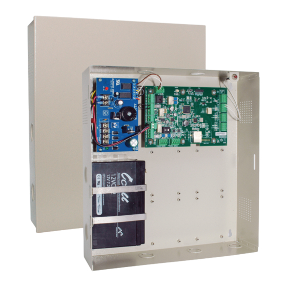
Power Supply: Provides the DC power required for operation of the controller PCB and all peripherals Controller Board (PCB): Controls all the features of the RAC5 XT system Tamper Switch: Attached to the RAC5 XT enclosure to generate an alarm if the box is opened during operation 12-2020 dormakaba Canada Inc. -
Page 8: Contactless Card Reader
Figure 4 – Contactless Card Reader 2.2.3 Locking Devices The RAC5 XT controller PCB provides one or multiple relay outputs that can be used to control Electric Strikes (K) or Electromagnetic Locks (L) as shown below. Figure 5 – Electric Strike & Electromagnetic Lock 12-2020 dormakaba Canada Inc. -
Page 9: Optional Peripherals
2.2.4 Optional Peripherals The RAC5 XT can also be used with the following peripherals: Exit Devices • Motion Detectors • Panic Bars • Request to Exit (REX) button • Remote Unlock button • Remote Programming Interface • 3 Checklist and Exploded Views 3.1 Parts and Tools List... -
Page 10: Cables (Not Shown)
Request to Exit button (REX) Remote Unlock (not shown) 3.1.8 Programming Device NOTE: Purchased separately, dependent on hotel configuration. Programming of the RAC5 XT can only be done with the M-Unit. IMPORTANT 3.1.9 Installation Hardware Bag 4x Philips wood screw, #8 x 1-1/4”... -
Page 11: Tools Required (Not Supplied)
Wire cutter/stripper • Ambiance or System 6000 via the M-Unit • Hammer or rubber mallet • Awl or centre punch 3.2 Exploded View Figure 6 – Exploded View 12-2020 dormakaba Canada Inc. RAC5 XT Installation Guide – PK3737 | 10... -
Page 12: System Installation Overview
Do not connect power to the enclosure until the end of the installation process. If installing CAUTION the RAC5 XT in an elevator cage environment, or in proximity to any other equipment that may generate high levels of electromagnetic interference, follow the installation requirements as indicated in Annex C to prevent any operational instability. -
Page 13: Installation And Wiring Procedures
Determine the routing needed for all wiring of the RAC5 XT card reader and peripherals and select the enclosure knock-out(s) to be removed for installation of the strain relief(s) b) Remove the selected knock-out(s) using a hammer and screwdriver / awl, and from the... -
Page 14: Mount The Contactless Card Reader
The actual items to connect will vary based on the system configuration ordered. 4.2.3.1 Electric Strike or Electromagnetic Lock (Locking Device) Refer to Annex B for detailed wiring. dormakaba Canada Inc. does not provide technical or field support for third party locking IMPORTANT devices. Please consult the device manufacturer for support. -
Page 15: Request To Exit Button (Rex)
2. Mount the device at the desires location and run a 2-conductor cable from the remote unlock button to the controller PCB connector J8, pins 1 & 2. Connect as per Annex B. 12-2020 dormakaba Canada Inc. RAC5 XT Installation Guide – PK3737 | 14... -
Page 16: Motion Detector
2. Route the wires out of the enclosure to the AC power source and secure the wires (recommended with tie wraps). 3. Crimp the fork terminals supplied in the hardware bag to the end of the wires and connect them to the power adapter screw terminals. 12-2020 dormakaba Canada Inc. RAC5 XT Installation Guide – PK3737 | 15... -
Page 17: Complete The Installation
4.2.5 Complete the Installation If the access door was removed, reinstall the door to the RAC5 XT enclosure. 2. Bend the two tabs on the door to a maximum of 30 degrees as shown in Figure 9. Figure 9 – Door Tabs 3. -
Page 18: Settings And Operation
10. If a Motion Detector is connected, pass in front of it to verify the door unlocks. 11. If the RAC5 XT is connected to a Fire Panel and the electromagnetic lock powered by the 12 VDC output of the RAC5 XT, verify that the electromagnetic lock or a fail-safe electric strike is deactivated when the Fire Alarm is active (open input). -
Page 19: Battery Back-Up Replacement
NOTE: For preventative maintenance, the battery back-up should be replaced every 2 to 3 years and tested every 6 months by removing the main AC power. Turn off the main AC power to the RAC5 XT or disconnect the power adapter from the wall outlet. 2. Disconnect the red and black wires from the battery. -
Page 20: New Battery Back-Up Installation
Do not exceed the load limitations of the control panel. CAUTION The maximum recommended load for the output relays in the RAC5 XT system is 1 Amp at 30 VDC. The tamper switch rating is 1 Amp at 30 VDC. -
Page 21: Annex A: Wiring Diagram And Tables
25mA at a minimum of 5V rating. J1 is rated for an output of 12V @ 500mA. J6 & J18 are rated for outputs of 12V @ 500mA. 12-2020 dormakaba Canada Inc. RAC5 XT Installation Guide – PK3737 | 20... -
Page 22: Annex B: Peripheral Wiring Diagrams
PWR GND GND PWR READE R 2 READE R 1 1 (+) 2 (-) 3 (+) 4 (-) RD#1 RD#2 Green Black White Maximum cable length of 1000 Feet 12-2020 dormakaba Canada Inc. RAC5 XT Installation Guide – PK3737 | 21... - Page 23 J6 pin 1 which would be connected to COM J15 pin 1 with the Strike connected to NO J15 pin 3 and the Ground connection would be connected to J6 pin 2. 12-2020 dormakaba Canada Inc. RAC5 XT Installation Guide – PK3737 | 22...
- Page 24 Bypass wire and connect J18 to the Fire Alarm panel as per Fire Alarm Panel Wiring diagram (see Annex B, Figure 10). In this case the Electric Strike MUST be powered from the RAC5 XT’s +12V output as shown in this diagram.
- Page 25 Locking Device Note: If the locking device is inductive (such as a strike) place a diode across the locking device’s terminals as shown in the strike wiring diagrams. 12-2020 dormakaba Canada Inc. RAC5 XT Installation Guide – PK3737 | 24...
- Page 26 1 (+) 2 (-) 3 (+) 4 (-) RD#1 RD#2 Power Supply NOTE: If the second reader is not used on RAC5 XT, the motion detector can be powered from J1, pin 3 (12V) Motion and 4 (GND). Detector 12-2020...
- Page 27 Note 2: If the Fire Alarm Panel connection is not required, place a jumper wire between pin 3 and 4 of J18. Figure 20 – Power Adapter to Power Supply PCB Wiring Power Adaptor Power Supply 12-2020 dormakaba Canada Inc. RAC5 XT Installation Guide – PK3737 | 26...
-
Page 28: Annex C: Electromagnetic Interference
8 Annex C: Electromagnetic Interference As per any other electronic equipment, the RAC5 XT can be affected by electromagnetic inference caused by industrial electrical equipment, such as elevator motors. To prevent the unit from operational instability, such as ‘freezing’ or losing programming, shielded cables should be used and connections made as per the diagram below. -
Page 29: Annex D: Quick Troubleshooting Guide
If using the 24 VDC international adapter, verify the polarity is correct Power supply DC ON red LED is • Verify the wiring between the power supply and the RAC5 XT controller • Verify the power supply output is not shorted •... -
Page 30: Card Reading Troubleshooting
9.2 Card Reading Troubleshooting Symptom Action • Verify that the RAC5 XT controller is active. If not, reset the RAC5 XT controller: Press the Reset Switch (SW1) or disconnect and reconnect No feedback on Reader when the power using a card •... -
Page 31: Locking Device Troubleshooting
9.4 Locking Device Troubleshooting Symptom Action • If the Locking Device Relay LED (D31) on the RAC5 XT controller is ON: Verify that the lock is not in Passage Mode • • If the Locking Device Relay LED (D31) on the RAC5 XT controller is OFF: •... -
Page 32: Annex E: Reader Drilling Template
10 Annex E: Reader Drilling Template Figure 21 – Reader Drilling Template (not to scale) 12-2020 dormakaba Canada Inc. RAC5 XT Installation Guide – PK3737 | 31... - Page 33 Canada Inc. www.dormakaba.us...
Need help?
Do you have a question about the RAC5 XT and is the answer not in the manual?
Questions and answers