
Related Manuals for rtd DM35MRM128HR


Summary of Contents for rtd DM35MRM128HR
- Page 1 DM35MRM128HR 8x16 Switch Matrix User’s Manual BDM-610020160 Rev. A RTD Embedded Technologies, Inc. AS9100 and ISO 9001 Certified...
- Page 2 RTD Embedded Technologies, Inc. 103 Innovation Boulevard State College, PA 16803 USA Telephone: 814-234-8087 Fax: 814-234-5218 www.rtd.com sales@rtd.com techsupport@rtd.com...
- Page 3 Failure to follow the instructions found in this manual may result in damage to the product described in this manual, or other components of the system. The procedure set forth in this manual shall only be performed by persons qualified to service electronic equipment. Contents and specifications within this manual are given without warranty, and are subject to change without notice. RTD Embedded Technologies, Inc. shall not be liable for errors or omissions in this manual, or for any loss, damage, or injury in connection with the use of this manual.
-
Page 4: Table Of Contents
Differential Cabling Switch Matrix..................................... 18 4.3.1 Crosspoint Matrix DM35MRM128HR Configuration Register Address Space Troubleshooting Additional Information PC/104 Specifications ................................26 PCI and PCI Express Specification ............................26 Limited Warranty | www.rtd.com DM35MRM128HR User’s Manual RTD Embedded Technologies, Inc. BDM-610020160 Rev. A... - Page 5 Figure 7: CN6 Vin Power Connector ..................................13 Figure 8: CN6 Vin Power Connector Pin Assignments ............................13 Figure 9: Example 104™Stack ....................................15 Figure 10: DM35MRM128HR Block Diagram ................................. 16 Figure 11: NXP PCA9616 Example Circuit ................................17 Figure 12: PCA9616 Termination ................................... 17 Figure 13: Example 5x5 Matrix Crosspoint ................................
-
Page 6: Introduction
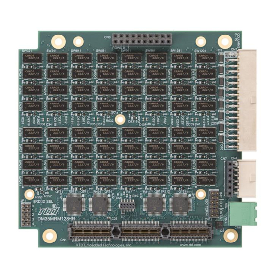
Product Overview The DM35MRM128HR is a stackable switch matrix module. This module consists of an 8x16 array of single pole (form A) rhodium contact reed relays. Each relay can be individually closed to connect a single column to a single row, and a combination of relay closures can form any desired network of connections. - Page 7 ® ® built RTD HiDAN or HiDANplus High Reliability Intelligent Data Acquisition Node. Contact RTD sales for more information on our high reliability systems. | www.rtd.com DM35MRM128HR User’s Manual RTD Embedded Technologies, Inc. BDM-610020160 Rev. A...
-
Page 8: Contact Information
If you are having problems with your system, please try the steps in the Troubleshooting section of this manual on page 25. For help with this product, or any other product made by RTD, you can contact RTD Embedded Technologies technical support via the following methods: Phone: 1-814-234-8087 Monday through Friday, 8:00am to 5:00pm (EST). -
Page 9: Specifications
Switch Power Switch Current Carry Current Closed Switch Path Ω Open Switch Path Ω Bandwidth -3 dB, 50 Ω termination Channel-to-channel crosstalk 10 kHz 100 kHz 1 Mhz | www.rtd.com DM35MRM128HR User’s Manual RTD Embedded Technologies, Inc. BDM-610020160 Rev. A... -
Page 10: Board Connection
Handle the board in an antistatic environment and use a grounded workbench for testing and handling of your hardware. Physical Characteristics STEP model is available upon request; contact RTD Tech Support for more information. • Weight: Approximately 0.25 lbs. (0.11 Kg) •... -
Page 11: Connectors And Jumpers
Figure 3 CN8 Rows Connector ROW 0 ROW 2 ROW 4 ROW 6 ROW 1 ROW 3 ROW 5 ROW 7 Table 4: CN8 Rows Connector Pin Assignments | www.rtd.com DM35MRM128HR User’s Manual RTD Embedded Technologies, Inc. BDM-610020160 Rev. A... -
Page 12: Cn3: Columns Connector
CN4 is a 0.1” 6-pin right angle cabled I2C connector. An example of its’ mating connector is the Samtec IPD1-06-S-K. Pin 1 is indicated by a square pad on both the top and bottom of the board. Figure 5: CN4 Cabled I2C Connector | www.rtd.com DM35MRM128HR User’s Manual RTD Embedded Technologies, Inc. BDM-610020160 Rev. A... -
Page 13: Cn7: Stack Through I2C Connector
CN16: PCI Connector The PCI connector is the connection to PCI peripheral modules. The position and pin assignments are compliant with the PCI/104-Express Specification. (See PC/104 Specifications on page 26) | www.rtd.com DM35MRM128HR User’s Manual RTD Embedded Technologies, Inc. BDM-610020160 Rev. A... -
Page 14: Jumpers
An ‘X’ indicates a closed jumper, while an empty cell indicates an open jumper. I2C base address Jumpers (Hexadecimal) Table 7: I2C base address | www.rtd.com DM35MRM128HR User’s Manual RTD Embedded Technologies, Inc. BDM-610020160 Rev. A... -
Page 15: Steps For Installing
11. Re-connect the power cord and apply power to the stack. 12. Boot the system and verify that all the hardware is working properly. Figure 9: Example 104™Stack | www.rtd.com DM35MRM128HR User’s Manual RTD Embedded Technologies, Inc. BDM-610020160 Rev. A... -
Page 16: Functional Description
4.2.1 ONTROLLER NFORMATION In this section RTD provides information about the NXP PCA9616 buffer that is used on the DM35MRM128HR to provide the differential I C bus. If you do not use the CM35I2C03HR as a host I C host, the information below can be used to develop a differential I C interface for your host module. -
Page 17: Nxp Pca9616 Buffer
C interface is designed for 100Ω impedance transmission lines. Using the termination circuit shown above, RTD suggest using CAT5, CAT6, or CAT7 data cable for cabling between host and slave. CAT5, CAT6 and CAT7 provide 4 twisted pairs, the 4 pairs can be used for 3 signals (INT, CLK, DATA) and power. -
Page 18: Switch Matrix
Switch Matrix The DM35MRM128HR is a high-density matrix module consisting of 8 rows by 16 columns of type A reed relays. This configuration allows for 128 crosspoints. This allows for users to programmatically switch wiring configuration as needed, this makes for a perfect tool for DUT (device under test) testing. -
Page 19: Register Address Space
OMMANDS EGISTER This register contains how many valid write registers are in the module. The DM35MRM128HR has separate read and write pointers. The write pointer starts at 0x00, the last valid write register is value of this register minus one. - Page 20 OMMANDS EGISTER This register contains how many valid read registers are in the module. The DM35MRM128HR has separate read and write pointers. The read pointer starts at 0x00, the last valid read register is value of this register minus one.
- Page 21 0 controls column 0). It is not required to read both bytes. Address Bits Description 0x0C Lower Byte corresponds to the columns 0-7 0x0D Upper Byte corresponds to the columns 8-15 | www.rtd.com DM35MRM128HR User’s Manual RTD Embedded Technologies, Inc. BDM-610020160 Rev. A...
- Page 22 0x60 Bits 7:0 of the build number 0x61 Bits 15:8 of the build number 0x62 Bits 23:16 of the build number 0x63 Bits 31:24 of the build number | www.rtd.com DM35MRM128HR User’s Manual RTD Embedded Technologies, Inc. BDM-610020160 Rev. A...
- Page 23 Write Command Set The figure below provides a summary of the DM35MRM128HR I C Write Command Set. Table 9: I C Write Command Set Name Address Bank 0 Shadow 0x00-0x01 Configures the relay of bank 0. You may configure each byte individual.
- Page 24 This register is used to set the readback pointer. The value written into this will be the first address that is return when issue a read to the controller. Note this register will self-increment after the Host ACKnowledges at the end of each data sequence. Bits Description Reserved | www.rtd.com DM35MRM128HR User’s Manual RTD Embedded Technologies, Inc. BDM-610020160 Rev. A...
-
Page 25: Troubleshooting
If problems persist, or you have questions about configuring this product, contact RTD Embedded Technologies via the following methods: Phone: +1-814-234-8087 E-Mail: techsupport@rtd.com Be sure to check the RTD web site (http://www.rtd.com) frequently for product updates, including newer versions of the board manual and application software. | www.rtd.com DM35MRM128HR User’s Manual RTD Embedded Technologies, Inc. -
Page 26: Additional Information
PCI and PCI Express Specification A copy of the latest PCI and PCI Express specifications can be found on the webpage for the PCI Special Interest Group: www.pcisig.com | www.rtd.com DM35MRM128HR User’s Manual RTD Embedded Technologies, Inc. BDM-610020160 Rev. A... -
Page 27: Limited Warranty
RTD Embedded Technologies, Inc. warrants the hardware and software products it manufactures and produces to be free from defects in materials and workmanship for one year following the date of shipment from RTD Embedded Technologies, Inc. This warranty is limited to the original purchaser of product and is not transferable. - Page 28 RTD Embedded Technologies, Inc. 103 Innovation Boulevard State College, PA 16803 USA Telephone: 814-234-8087 Fax: 814-234-5218 www.rtd.com sales@rtd.com techsupport@rtd.com Copyright 2024 by RTD Embedded Technologies, Inc. All rights reserved.
Need help?
Do you have a question about the DM35MRM128HR and is the answer not in the manual?
Questions and answers