Table of Contents
Advertisement
Quick Links
IM
Installation Manual
CAP 30/Flex
662950-0100
ScrewCap
WARNING
Read and follow all safety precaution instructions throughout this
manual and on safety signs attached to this equipment.
Failure to follow all safety precaution instructions could result in death or
serious injury.
Doc. No. IM-2852922-0103
Advertisement
Chapters
Table of Contents

Subscribe to Our Youtube Channel
Related Manuals for Tetra Pak CAP 30/Flex ScrewCap


Summary of Contents for Tetra Pak CAP 30/Flex ScrewCap
- Page 1 Installation Manual CAP 30/Flex 662950-0100 ScrewCap WARNING Read and follow all safety precaution instructions throughout this manual and on safety signs attached to this equipment. Failure to follow all safety precaution instructions could result in death or serious injury. Doc. No. IM-2852922-0103...
- Page 2 Tetra Pak products are trademarks belonging to the Tetra Pak Group. The content of this manual is in accordance with the design and construction of the machine or equipment at the time of publishing. Tetra Pak reserves the right to introduce design modifications without prior notice.
- Page 3 4 Positioning, Assembly and Connections 5 Final Installation Check 6 Preparation for Commissioning 7 Disassembly and Removal Machine or equipment configurations that this manual is valid for are described on the next page. Doc. No. IM-2852922-0103 Issue 2007-10 Tetra Pak Packaging Solutions...
- Page 4 Valid for: Name Drawing Specification Additional Information and Development Step CAP 30/Flex ScrewCap 662950-0100 TBA 500 Sq StreamCap 1000 TBA 1000 Sq StreamCap 1000 TBA 1000 S SlimCap 1000 TBA 1500 S SlimCap 1000 TBA 1890 S SlimCap 2000 TBA 2000 S SlimCap 2000...
- Page 5 i Introduction i - 1 Doc. No. IM-2852922-0103 (14)
- Page 6 Introduction About the Introduction Chapter This chapter contains basic information about this manual and the related Tetra Pak equipment. i - 2 Doc. No. IM-2852922-0103 (14)
-
Page 7: Table Of Contents
Table of Contents i Introduction Abbreviations and Terminology ....i - 5 Manual Information ......i - 7 Delivered Manuals . - Page 8 i Introduction This page intentionally left blank i - 4 Doc. No. IM-2852922-0103 (14)
-
Page 9: Abbreviations And Terminology
Abbreviations and Terminology i Introduction Abbreviations and Terminology Abbreviation/ Meaning Translation Terminology Ampere ANSI American National Standards Institute Base (package shape) Cap Applicator Communautés Européennes/European Communities Cont’d Continued Decibel Distribution Equipment Deg. Degree Doc. Document European Economic Area Electrical Manual Foot / feet Hertz kilogram... - Page 10 Packaging Line Monitoring System Position Pound per square inch Polyvinyl chloride Slim (package shape) sec. Second Spare Parts Catalogue Square (package shape) Tetra Brik Aseptic Technical Manual Tetra Pak Tetra Prisma Aseptic Volt i - 6 Doc. No. IM-2852922-0103 (14)
-
Page 11: Manual Information
It is important to keep this manual for the lifetime of the equipment and to pass the manual on to any subsequent holder or user. Tetra Pak will not be held responsible for any damage to the equipment caused by not following the instructions given in this manual. -
Page 12: Page Layout
Manual Information i Introduction Page Layout Every main page in a manual contains a header and a footer. The page header contains the chapter name (1) and the section name (2). The page footer contains the page number (3), and the document number (4). See also the Page Numbering section. -
Page 13: Page Numbering
Manual Information i Introduction Page Numbering A page number has three parts: • chapter number (1) • consecutive page number (2) within the chapter • total number of pages (3) in the chapter. 4 - 11 (18) 1 Chapter number 2 Consecutive page number 3 Total number of pages Typographical Conventions... -
Page 14: Machine Introduction
Introduction Machine Introduction Intended Use of the Equipment The intended use of this Tetra Pak equipment is to apply a closure onto a package. Tetra Brik Aseptic Slim packages with SlimCaps or ReCaps must have opening tabs. The opening tabs are applied by a PullTab unit which is incorporated in to the filling machine. -
Page 15: Identification
The illustration below shows an example of the machine plate and its location on the equipment. The machine plate carries data needed when contacting Tetra Pak concerning this specific equipment. Make sure that the equipment data in the front pages of this manual corresponds to the machine plate data and the machine specification. -
Page 16: Orientation
Orientation i Introduction Orientation The illustration below shows the orientation of the equipment. This orientation information will be used throughout this manual. The arrows indicate the flow of material. A Front B Back C Left D Right E Infeed F Outfeed i - 12 Doc. -
Page 17: Hygiene
Hygiene i Introduction Hygiene Packaging Material Avoid microbiological contamination of the packaging material: • Always protect your packaging material against contamination. Do not let the caps come into contact with contaminated areas. Only use caps direct from their packaging material. •... - Page 18 Hygiene i Introduction This page intentionally left blank i - 14 Doc. No. IM-2852922-0103 (14)
- Page 19 ii Safety Precautions ii - 1 Doc. No. IM-2852922-0103 (30)
- Page 20 ii Safety Precautions Safety Precaution Instructions WARNING Read all safety precaution instructions throughout this manual and on safety signs attached to this equipment. Failure to follow all safety precaution instructions could result in death or serious injury. Definition of Lockout Procedure A lockout procedure is a procedure to put each necessary energy isolating device in its safe position to prevent the energisation of the equipment, such as when a maintenance procedure should be carried out.
- Page 21 Table of Contents ii Safety Precautions Safety Messages Description....ii - 5 Personnel Requirements ....ii - 6 Skilled Person .
- Page 22 Table of Contents ii Safety Precautions Hotmelt Equipment ..... . . ii - 24 General ........ii - 24 Hotmelt Unit .
-
Page 23: Safety Messages Description
Safety Messages Description ii Safety Precautions Safety Messages Description A safety message is always accompanied by a safety alert symbol and a signal word. The safety alert symbol is used to alert about potential personal injury hazards. To avoid hazards, obey all safety messages that follow this symbol. The following safety alert symbols and signal words are used in this manual to inform the user of hazards. -
Page 24: Personnel Requirements
Personnel Requirements ii Safety Precautions Personnel Requirements Note! Personnel includes all persons working on or near this equipment. Only skilled or instructed persons are allowed to work with this equipment. Skilled Person A skilled person must have relevant education and experience to enable him or her to identify hazards, analyse risks, and avoid hazards which electricity, machinery, chemicals, other energies, and supply systems on this equipment can create. -
Page 25: Safety Signs
Safety Signs ii Safety Precautions Safety Signs WARNING Damaged or missing safety signs increase the risk of death or serious injury. Replace all missing or damaged safety signs immediately. Safety signs are attached to the equipment. The table below lists all the signs that are used, and illustrations show their locations on the equipment. - Page 26 Safety Signs ii Safety Precautions Pos. ISO sign ANSI sign Blade hazard. Do not touch the sharp knife. Blade hazard. Do not touch the sharp knife. ii - 8 Doc. No. IM-2852922-0103 (30)
-
Page 27: Location Of Safety Signs
Safety Signs ii Safety Precautions Location of Safety Signs The illustration shows where the safety signs are located. The position numbers refer to the table in the Safety Signs section. ii - 9 Doc. No. IM-2852922-0103 (30) -
Page 28: Protective Devices
Protective Devices ii Safety Precautions Protective Devices WARNING Hazardous zones. Hazardous zones are safeguarded and provided with protective devices. Do not inch or run this equipment if any protective device is inoperative. Change inoperative components of the safety system immediately. WARNING Hazardous voltage. -
Page 29: Emergency Stop Push-Buttons
Protective Devices ii Safety Precautions Emergency Stop Push-Buttons Press one of the EMERGENCY STOP push-buttons to stop this equipment immediately. The location of each EMERGENCY STOP push-button is shown by an arrow. ii - 11 Doc. No. IM-2852922-0103 (30) -
Page 30: Safeguards
Protective Devices ii Safety Precautions Safeguards WARNING Moving machinery. Never defeat or bypass the interlocking devices. Movable guards, for example, doors and covers leading to hazardous zones, are fitted with interlock devices where required. These devices are usually electric safety switches that are part of the safety system and must never be defeated, bypassed, or otherwise made inoperative. - Page 31 Protective Devices ii Safety Precautions (Cont'd) CAUTION Equipment damage. Never stop this equipment by opening a movable guard with an interlock device installed. Movable guards with safety switches installed are shown by an arrow. Movable guards with an electromagnetic door lock installed are shown by an arrow.
-
Page 32: Warning Lamp
Protective Devices ii Safety Precautions Warning Lamp A warning lamp is a column of warning lights: • A red light (1) indicates a hazardous condition. This is a situation that requires immediate action. • A yellow light (2) indicates an abnormal or impending critical condition. This is a condition calling for action by the operator. -
Page 33: Personal Protection
Personal Protection ii Safety Precautions Personal Protection This section applies to all personnel at all times when this equipment is in operation. For special personal protection required when handling hazardous substances, see the Hazardous Substances section. Noise Hazard WARNING Hazardous noise. Risk of impaired hearing. -
Page 34: Hazardous Substances
Hazardous Substances ii Safety Precautions Hazardous Substances WARNING Contact with chemicals can cause death, serious injury, or illness. Always read and follow the instructions in the safety data sheet supplied by the manufacturer or local supplier, when handling chemicals. Make sure that •... -
Page 35: Determelt 3
Hazardous Substances ii Safety Precautions Determelt 3 WARNING Risk of personal injury. Wear personal protective equipment. Determelt 3 is a blend of orange oils, mineral spirits and antioxidant. Determelt 3 is used to remove hotmelt from metal machine parts, such as, the cap holders and should only be used neat. -
Page 36: Handling
Hazardous Substances ii Safety Precautions (Cont'd) Handling WARNING Risk of Self-ignition. Self-ignition can occur at temperature more than 200°C (392°F). Determelt 3 can only be used neat and used cold. Never pour on hot surfaces or turn on hotmelt applications. Ensure that equipment to be cleaned is cool and all supplies to the equipment are OFF. -
Page 37: Disposal Of Chemical Substances
Hazardous Substances ii Safety Precautions Disposal of Chemical Substances Always read and follow the disposal instructions in the safety data sheet supplied by the manufacturer or local supplier. It is strongly recommended that used chemical containers are • Disposed of according to the instructions immediately after use •... -
Page 38: Supply Systems
Supply Systems ii Safety Precautions Supply Systems Power Supply DANGER Hazardous voltage and moving machinery. The power supply disconnector must be turned off and secured with a lock before any maintenance. Note! The key to the lock must be removed by the technician and retained in his/her possession until all work is completed. -
Page 39: Electrical Cabinet
Supply Systems ii Safety Precautions Electrical Cabinet DANGER Hazardous voltage. Will shock, burn, or cause death. The power supply disconnector must be turned off and secured with a lock before maintenance inside the electrical cabinet. Note! The key to the lock must be removed by the technician and retained in his/her possession until all work is completed. -
Page 40: Socket Outlet
Supply Systems ii Safety Precautions Socket Outlet WARNING Hazardous voltage. Can shock, burn, or cause death. Read the Maintenance Manual before using this socket outlet. The socket outlet (1) is connected to a residual current device (2) to protect users against electrical shock if there is an earth fault in the connected equipment. -
Page 41: Air Supply
Supply Systems ii Safety Precautions Air Supply WARNING Compressed air and moving machinery. Close the main air valve and secure it with a lock before any maintenance. Note! The key to the lock must be removed by the technician and retained in his/her possession until all work is completed. -
Page 42: Hotmelt Equipment
Note! Always refer to the documentation provided from Nordson Corporation before doing any kind of work on the hotmelt equipment. The Nordson hotmelt manual is included with the delivery from Tetra Pak. The information in this manual only deals with what is specific for this machine. -
Page 43: Hotmelt Unit
Supply Systems ii Safety Precautions Hotmelt Unit CAUTION Risk of damage to the equipment. Never flush water or any other liquid towards the hotmelt unit when cleaning the machine. Failure to obey could result in damage to equipment. WARNING Risk of burns. During PREHEATING and PREPARTION the hotmelt unit becomes hot. -
Page 44: Hotmelt Guns
Supply Systems ii Safety Precautions Hotmelt Guns WARNING Risk of burns. During PREHEATING, PREPARTION and PRODUCTION the hotmelt guns are hot. There is risk of severe burns. Do not touch the hotmelt guns and beware of the entrapped heat when service is performed. CAUTION Risk of damage to the equipment. -
Page 45: Additional Information
Additional Information ii Safety Precautions Additional Information Package Heater WARNING Risk of burns. The package heater is very hot and there is risk of severe burns. Never touch the package heater. ii - 27 Doc. No. IM-2852922-0103 (30) -
Page 46: Cap Detector
Additional Information ii Safety Precautions Cap Detector WARNING Risk of personal injury. Never put any part of the body, such as a hand, near the cap detector when the machine is working. There is a risk of injury caused by the movable pusher. -
Page 47: Equipment For Lifting And Moving Loads
Equipment for Lifting and Moving Loads ii Safety Precautions Equipment for Lifting and Moving Loads WARNING Risk of crushing injury. Make sure that the capacity of the lifting equipment is adequate and that the equipment itself is in good working order. If lifting tackle has to be joined to make up the necessary length, make sure that the joints are secure and have the same lifting capacity as the rest of the lifting tackle. - Page 48 Equipment for Lifting and Moving Loads ii Safety Precautions This page intentionally left blank ii - 30 Doc. No. IM-2852922-0103 (30)
- Page 49 1 Technical Data and Drawings 1 - 1 Doc. No. IM-2852922-0103 (24)
- Page 50 1 Technical Data and Drawings Technical Data and Drawings - Description This chapter includes drawings showing machine dimensions and connection positions. Values are in millimetres unless otherwise stated. All dimensions must be respected. 1 - 2 Doc. No. IM-2852922-0103 (24)
- Page 51 Table of Contents 1 Technical Data and Drawings 1.1 Installation Drawings..... . 1 - 5 1.1.1 Cap Applicator - Left View....1 - 5 1.1.2 Top.
- Page 52 Table of Contents 1 Technical Data and Drawings 1.5.1 Machine Capacity ......1 - 20 1.5.2 Ambient Temperature ..... 1 - 20 1.6 Conveyor .
-
Page 53: Installation Drawings
1.1 Installation Drawings 1 Technical Data and Drawings 1.1 Installation Drawings 1.1.1 Cap Applicator - Left View 2800 1140 2340 2630 1 - 5 Doc. No. IM-2852922-0103 (24) -
Page 54: Top
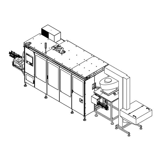
1.1 Installation Drawings 1 Technical Data and Drawings 1.1.2 Top Note! For conveyor lengths and conveyor details, see 1.6 Conveyor. The cap sorter positions are shown in the illustration below. 2050 1586 1235 1500 1 - 6 Doc. No. IM-2852922-0103 (24) -
Page 55: Working Area
1.1 Installation Drawings 1 Technical Data and Drawings 1.1.3 Working Area 4400 1100 1100 3300 1 - 7 Doc. No. IM-2852922-0103 (24) -
Page 56: Drive And End Unit
1.1 Installation Drawings 1 Technical Data and Drawings 1.1.4 Drive and End Unit The illustration below shows the location of DE units, the distances to be respected and the installation requirements for these units. 1 DE unit 2 DE unit 3 Package conveyor 4 DE unit 5 Electrical cabinet... -
Page 57: General
1.1 Installation Drawings 1 Technical Data and Drawings (Cont'd) 1.1.4.1 General A DE unit (1) is installed at the infeed to the cap applicator (see picture in the previous page). The DE unit (1) is not controlled by the cap applicator. To pull the chain (package conveyor) through the cap applicator, a DE unit (2) is installed at the discharge (front) of the cap applicator. -
Page 58: Cap Detector
1.1 Installation Drawings 1 Technical Data and Drawings 1.1.5 Cap Detector The cap detector (1) is installed at the front of the cap applicator (2). The cap detector removes a package that has no cap from the package conveyor (3). Top view 1 Cap detector 2 Cap applicator (front panel) -
Page 59: Sensors Position
1.1 Installation Drawings 1 Technical Data and Drawings 1.1.6 Sensors Position The sensor too long package queue (1) is installed 1 m before the DE unit (2) (distance A). This sensor is connected but is not used. The illustration below shows the location of long package queue sensor (3), verify package standing sensor (4), short package queue sensor (5) referring to the rear of belt brake (6), see the MM. -
Page 60: Service Connection
1.1 Installation Drawings 1 Technical Data and Drawings 1.1.7 Service Connection A = 240 mm B = 180 mm C = 110 mm D = 150 mm E = 480 mm 1 Water connection 2 Air connection 3 Electrical connection 1 - 12 Doc. -
Page 61: System Drawings
1.1 Installation Drawings 1 Technical Data and Drawings 1.1.8 System Drawings System drawings are located in the electrical cabinet. System drawings are as follows: • Installation drawings • Pneumatic diagram • Lubrication diagram • Extra equipment (if relevant). 1 - 13 Doc. -
Page 62: Mass (Weight)
1.2 Mass (Weight) 1 Technical Data and Drawings 1.2 Mass (Weight) 1.2.1 Weight and Dimensions All weights are estimates. Machine Configuration Mass (weight) Notes Cap Applicator 30/Flex 2800 kg (6175 Ibs) Cap sorter Flex 387 kg (835 lbs) 1.2.2 Centre of Gravity and Lifting Points Cap Applicator WARNING Risk of serious personal injury. - Page 63 1.2 Mass (Weight) 1 Technical Data and Drawings Cap Sorter 1 Centre of gravity 2 Recommended fork lift points Infeeder 360* 1 Centre of gravity * 420 mm when horizontal for transporting 2 Recommended fork lift points 1 - 15 Doc.
-
Page 64: Utility Connection Data
1.3 Utility Connection Data 1 Technical Data and Drawings 1.3 Utility Connection Data 1.3.1 Electrical Power 1.3.1.1 Electrical Power Specification Note! For more information, see the Mains Connection Diagrams in the EM. Characteristic Value Notes Supply voltage 400 VAC, 3 phase + N + PE Supply cable cross 4 or 6 mm section... -
Page 65: Compressed Air
1.3 Utility Connection Data 1 Technical Data and Drawings 1.3.2 Compressed Air 1.3.2.1 Compressed Air Requirements • Oil is invariably introduced into compressed air from oil-lubricated compressors and must be removed as completely as possible. Oil is a serious pollutant which is difficult to remove from instruments. •... -
Page 66: Compressed Air Consumption
1.3 Utility Connection Data 1 Technical Data and Drawings 1.3.2.3 Compressed Air Consumption Machine configuration Average consumption Peak consumption during production (duration < 2 sec.) Cap Applicator 30/Flex 500 ±16 Nl/min 680 ±18 Nl/min 1.3.3 Water 1.3.3.1 Cold Water Supply Characteristic Value Notes... -
Page 67: Noise
1.4 Noise 1 Technical Data and Drawings 1.4 Noise The tables below gives the noise level measurements for the machine under the following conditions: • Machine on a concrete floor supported by standard feet • Production under normal operating conditions. Note! Emission sound pressure / power values in accordance with ISO 4871. -
Page 68: Product Data
1.5 Product Data 1 Technical Data and Drawings 1.5 Product Data 1.5.1 Machine Capacity Machine capacity is cap and package dependent. Machine configuration Production Capacity Notes (pack/hour) Cap Applicator 30/Flex 6600 The applicator capacity is 7200 20% more than the filling 8400 machine. - Page 69 1.6 Conveyor 1 Technical Data and Drawings 1.6 Conveyor 1.6.1 Data 1.6.1.1 Infeed/Discharge Characteristic Value Type Package Conveyor PC23 Width 40 to 78 mm (adjustable) Height 825 ±50 mm Standard Speed 25 m/min 1.6.1.2 Conveyor Speed If necessary to change the speed of the conveyor, go to the System Setting window in the control panel and select the PACKAGE POSITIONER (PP) button, see the OM.
- Page 70 1.7 Additional Information 1 Technical Data and Drawings 1.7 Additional Information 1.7.1 Conveyor Lubrication 1.7.1.1 Lubricants DICOLUBE KB This lubricant is for all types of packages and conveyors (TP No. 90459-0822) except the following; TB/TBA 200 S, TB/TBA 250 S, TBA 1000 Sq, all TPA and TGA -packages, all Tetra Top packages, all Tetra Rex packages and all packages printed with water soluble colours.
- Page 71 TP 85. • one lubrication nozzle for each Drive & End unit. Type of nozzle: Green, flow 0.05 l/min. Part 534270-101. Note! Conveyor lubricants can be ordered from Tetra Pak Parts AB. 1 - 23 Doc. No. IM-2852922-0103 (24)
- Page 72 1.7 Additional Information 1 Technical Data and Drawings This page intentionally left blank 1 - 24 Doc. No. IM-2852922-0103 (24)
- Page 73 2 Preparation 2 - 1 Doc. No. IM-2852922-0103...
- Page 74 2 Preparation Preparation - Description This chapter describes the preparation requirements for the installation of the equipment. 2 - 2 Doc. No. IM-2852922-0103...
- Page 75 Table of Contents 2 Preparation 2.1 Requirements......2 - 5 2.1.1 General Requirements..... . 2 - 5 2.1.1.1 Personnel .
- Page 76 2 Preparation This page intentionally left blank 2 - 4 Doc. No. IM-2852922-0103...
-
Page 77: Requirements
The floor should be strong enough to support the full weight of the machine. Access is required for a fork lift or lifting equipment. 2.1.1.1 Personnel Only skilled or instructed Tetra Pak installation personnel are allowed to assemble the machine. 2.1.2 Space Requirements WARNING Risk of personal injury. -
Page 78: Installation Area
2.1 Requirements 2 Preparation (Cont'd) 2.1.2.2 Installation Area a) Make sure that all customer preparation work has been completed to prepare the site for the machine. b) Make sure that all the necessary utility supplies are available, see section 1 Technical Data and Drawings. c) Clear all obstacles away from the installation site and, if necessary, clean the floor of the site before starting to install the machine. -
Page 79: Special Tools, Auxiliary Equipment And Information
2.2 Special Tools, Auxiliary Equipment and Information 2 Preparation 2.2 Special Tools, Auxiliary Equipment and Information 2.2.1 Tools and Materials The following tools and materials are needed to move and install the equipment: • two hydraulic jacks, min capacity 3 tons •... -
Page 80: Lifting Equipment Specification For Crated
2.2 Special Tools, Auxiliary Equipment and Information 2 Preparation (Cont'd) 2.2.2.2 Lifting Equipment Specification for Crated Equipment Make sure that the lifting equipment complies with the specifications given in the following table. Equipment or Lifting Notes lifting tackle capacity kg (lbs) Fork lift 5000 A higher capacity fork lift truck allows the... -
Page 81: Equipment
3 Moving and Unpacking the Equipment 3 - 1 Doc. No. IM-2852922-0103 (14) - Page 82 3 Moving and Unpacking the Equipment Moving and Unpacking the Equipment - Description This chapter describes the safest way to transport, store and unpack the crated equipment before installation. 3 - 2 Doc. No. IM-2852922-0103 (14)
- Page 83 Table of Contents 3 Moving and Unpacking the Equipment 3.1 Crate Handling ......3 - 5 3.1.1 Crate Data .
- Page 84 3 Moving and Unpacking the Equipment This page intentionally left blank 3 - 4 Doc. No. IM-2852922-0103 (14)
- Page 85 3.1 Crate Handling 3 Moving and Unpacking the Equipment 3.1 Crate Handling 3.1.1 Crate Data Note! The Cap Applicator 30 Flex is delivered in one crate. See the packing list for a complete list of all parts included in the crate. Note! The weight of the crate will increase significantly if the crate becomes wet.
-
Page 86: Crate Handling
3.1 Crate Handling 3 Moving and Unpacking the Equipment 3.1.2 Lifting and Unloading WARNING Risk of personal injury. To ensure safe and efficient handling of the crate, carefully study the following instructions. 3.1.2.1 Equipment for Lifting and Moving For the type of lifting and moving equipment required, see 2.2 Special Tools, Auxiliary Equipment and Information. -
Page 87: Centre Of Gravity
3.1 Crate Handling 3 Moving and Unpacking the Equipment 3.1.2.3 Centre of Gravity WARNING Risk of personal injury. The crate may tilt if you do not observe the centre of gravity symbol. Failure to observe may result in personal injury and/or major damage to equipment. The purpose of the illustration below is to give an example of how the centre of gravity is indicated on a crate. -
Page 88: Using An Overhead Gantry Or Mobile Crane
For capacity and length of the lifting tackle, see 2.2.2 Equipment for Lifting and Moving. Use ropes or poles to steady and manoeuvre loads. Do not use hands or feet. Tetra Pak 3 - 8 Doc. No. IM-2852922-0103 (14) -
Page 89: Using A Fork Lift
3.1 Crate Handling 3 Moving and Unpacking the Equipment 3.1.2.5 Using a Fork Lift WARNING Risk of personal injury. The crate may tilt if you do not observe the centre of gravity symbol. Failure to observe may result in personal injury and/or major damage to equipment. The crates are marked with centre of gravity symbols (1). -
Page 90: Moving The Crated Equipment
3.1 Crate Handling 3 Moving and Unpacking the Equipment 3.1.3 Moving the Crated Equipment WARNING Risk of personal injury. Make sure the equipment can be lifted in accordance with the instruction in 3.1.2.3 Centre of Gravity. WARNING Risk of personal injury. The crate may tilt if you do not observe the centre of gravity symbol. -
Page 91: Storing The Crated Equipment
3.1 Crate Handling 3 Moving and Unpacking the Equipment 3.1.4 Storing the Crated Equipment CAUTION Risk of damage to the equipment. Do not stack the crates on top of each other. Store the crates indoors. Exposure to damp or to high or low temperatures may damage the equipment. -
Page 92: Unpacking Sequence
3.2 Unpacking Sequence 3 Moving and Unpacking the Equipment 3.2 Unpacking Sequence WARNING Risk of personal injury. Make sure there is sufficient room to move safely around the installation site. If machines around the site cannot be stopped, place guards around them to prevent accidental contact. -
Page 93: Inspection
3.2 Unpacking Sequence 3 Moving and Unpacking the Equipment 3.2.3 Inspection Open the machine document box and check that the documentation corresponds with the machine and the machine number. Use the packing list and check that all components are delivered. Examine the machine and the contents for damage. - Page 94 3.2 Unpacking Sequence 3 Moving and Unpacking the Equipment This page intentionally left blank 3 - 14 Doc. No. IM-2852922-0103 (14)
- Page 95 4 Positioning, Assembly and Connections 4 - 1 Doc. No. IM-2852922-0103 (24)
- Page 96 4 Positioning, Assembly and Connections Positioning, Assembly and Connections - Description This chapter describes the main activities to install the equipment. 4 - 2 Doc. No. IM-2852922-0103 (24)
- Page 97 Table of Contents 4 Positioning, Assembly and Connections 4.1 Transporting the Uncrated Machine ..4 - 5 4.1.1 General ........4 - 5 4.2 Positioning .
- Page 98 Table of Contents 4 Positioning, Assembly and Connections 4.6.3 Line Communication (Gateway Communication) ......4 - 24 4 - 4 Doc.
-
Page 99: Transporting The Uncrated Machine
4.1 Transporting the Uncrated Machine 4 Positioning, Assembly and Connections 4.1 Transporting the Uncrated Machine 4.1.1 General Before moving the machine into position for assembly and installation, check that the machine can be moved without problems regarding ceiling heights, doors, passages, etc. Obey the following warnings: WARNING Risk of personal injury. -
Page 100: Positioning
4.2 Positioning 4 Positioning, Assembly and Connections 4.2 Positioning WARNING Risk of personal injury. The machine can tilt if not observing the centre of gravity or the fork lift points, see 1.2 Mass (Weight). Failure to observe may result in personal injury and/or major damage to equipment. -
Page 101: Level The Equipment
4.3 Level the Equipment 4 Positioning, Assembly and Connections 4.3 Level the Equipment 4.3.1 Install the Machine Feet Install the machine feet (1) to the machine body. Set the feet to the initial distance of 250 mm. 4.3.2 Set the Machine Body Height Adjust the four feet (1) to set the machine body to the correct height. -
Page 102: Assembly
4.4 Assembly 4 Positioning, Assembly and Connections 4.4 Assembly This section gives the correct procedure for assembling the machine components. 4.4.1 Cooling Unit WARNING Risk of personal injury. Carefully follow the supplier’s instructions for handling the cooling unit. The cooling unit contains the refrigerant R134e (Freon). If a compressor leakage occurs in the cooling system this may cause serious freezing injuries if it comes in contact with bare skin. - Page 103 4.4 Assembly 4 Positioning, Assembly and Connections (Cont'd) a) Put the gasket (1) in position. b) Use the lifting equipment and lift the cooling unit (2) so that it is above the electrical cabinet (3). c) Put the electrical cable through the prepared hole (4) in the electrical cabinet (3).
-
Page 104: Warning Lamp
4.4 Assembly 4 Positioning, Assembly and Connections 4.4.2 Warning Lamp Install the warning lamp (1), see the EM for the electrical connections. 4 - 10 Doc. No. IM-2852922-0103 (24) -
Page 105: Roof Sections
4.4 Assembly 4 Positioning, Assembly and Connections 4.4.3 Roof Sections WARNING Risk of personal injury. The weight of each roof section (1), (2) and (3) is heavy. Two people are required to lift the roof sections into position. CAUTION Damage to the equipment. Be careful when lowering the roof sections on to the applicator. -
Page 106: Hotmelt Hose
4.4 Assembly 4 Positioning, Assembly and Connections 4.4.4 Hotmelt Hose a) Remove the bracket (1) from the side of the screwcap hotmelt applicator (2). b) Install the bracket (1) to the hotmelt applicator (2). c) Use the spring (3) to hold the hotmelt hose to the bracket (1). 1 Bracket 2 Hotmelt applicator 3 Spring... -
Page 107: Hotmelt Unit
4.4 Assembly 4 Positioning, Assembly and Connections 4.4.5 Hotmelt Unit a) Put the support (1) in position and install the four screws (2) and washers (3). b) Put the hotmelt unit (4) on the support (1) and install the screws (5). c) Connect the hotmelt hose (6) to the hotmelt unit (4). -
Page 108: Package Conveyor
4.4 Assembly 4 Positioning, Assembly and Connections 4.4.6 Package Conveyor a) Install the infeed package conveyor (1). b) Install the conveyor tunnel (2). 1 Infeed package conveyor 2 Conveyor tunnel 4 - 14 Doc. No. IM-2852922-0103 (24) -
Page 109: Cap Sorter
4.4 Assembly 4 Positioning, Assembly and Connections 4.4.7 Cap Sorter a) Install the cap sorter feet (1) to the cap sorter frame. Set the feet to the initial distance of 250 mm. b) Put the cap sorter in position. Adjust the four feet (1) to give the same height as the machine body. - Page 110 4.4 Assembly 4 Positioning, Assembly and Connections (Cont'd) d) Turn the handle (3) to move the infeeder (4) to give the correct height to the cap conveyor (5). For additional information, see the MM. e) Install the feet (6) to the elevator frame. f) Put the hopper (7) and the elevator (8) in position.
-
Page 111: Conveyor And Cap Detector
4.4 Assembly 4 Positioning, Assembly and Connections 4.4.8 Conveyor and Cap Detector WARNING Moving parts could cause serious injuries. The conveyor must be driven by a Drive and End unit with the electrical power supplied and controlled from the machine. Connected in any other way the conveyor could cause serious injuries to personnel. -
Page 112: Install
4.4 Assembly 4 Positioning, Assembly and Connections (Cont'd) 4.4.8.2 Install a) Remove the screw (1) and move the support bar (2) to one side. b) Put the conveyor (3) in position. c) Put the cap detector (4) in position and install the screws (5) to fix the cap detector (4) to the conveyors. -
Page 113: Connections
4.5 Connections 4 Positioning, Assembly and Connections 4.5 Connections 4.5.1 Electrical Connection 4.5.1.1 Power Supply DANGER Hazardous voltage. The voltage is 400V inside the electrical cabinet. This can cause electrical shock or serious injury. In case of accident, immediately call for medical attention. -
Page 114: Cap Detector
4.5 Connections 4 Positioning, Assembly and Connections 4.5.1.2 Cap Detector Connect the electrical cables from the sensors to the connectors on the electrical block (1). See the EM for sensor and connector identification. Sensor position TGA 1 Electrical block 4 - 20 Doc. -
Page 115: Cap Sorter
4.5 Connections 4 Positioning, Assembly and Connections 4.5.1.3 Cap Sorter a) Connect the electrical cable, 50W000 from the motor (1) to the connector (2) 50X000. The route of this cable is under the cap sorter and in the cable ducting. b) Connect the electrical cable, 50W100 from the motor (3) to the connector (4) 50X110. -
Page 116: Compressed Air
4.5 Connections 4 Positioning, Assembly and Connections 4.5.2 Compressed Air WARNING Risk of personal injury. Make sure that the air supply is OFF before performing any connection work. Connect the compressed air connection (1) as illustrated. Connect the compressed air (1) as illustrated. 1 Compressed air connection 4 - 22 Doc. -
Page 117: Water
4.5 Connections 4 Positioning, Assembly and Connections 4.5.3 Water Connect the water connection (1) as illustrated. 1 Water 4 - 23 Doc. No. IM-2852922-0103 (24) -
Page 118: Auxiliary Equipment
4.6 Auxiliary Equipment 4.6.1 General For the machine to work at its optimal efficiency, photocells, package traps and curves must be installed according to Tetra Pak recommendations, see 1.1 Installation Drawings. 4.6.2 PLMS PLMS software is installed in the machine. If PLMS data is required, it is necessary to connect a cable from the Helix machine to the applicator Genius bus in the electrical cabinet. - Page 119 5 Final Installation Check 5 - 1 Doc. No. IM-2852922-0103...
- Page 120 5 Final Installation Check Final Installation Check - Description This chapter describes the checks to do after installation work is completed and before commissioning this equipment. 5 - 2 Doc. No. IM-2852922-0103...
- Page 121 Table of Contents 5 Final Installation Check 5.1 Installation and Connection Checks ..5 - 5 5.2 Lubricant Level Checks ....5 - 6 5.3 Safety Checks .
- Page 122 5 Final Installation Check This page intentionally left blank 5 - 4 Doc. No. IM-2852922-0103...
- Page 123 5.1 Installation and Connection Checks 5 Final Installation Check 5.1 Installation and Connection Checks Use this check list to verify the completion of the installation work. Check Done Machine is level transversally and longitudinally. Utility connections work is done. Inspect the compressed air connection. Conveyor equipment is connected and level.
- Page 124 5.2 Lubricant Level Checks 5 Final Installation Check 5.2 Lubricant Level Checks See the MM for details on the following lubricant level checks. Check Done Machine body - Lubrication system. 5 - 6 Doc. No. IM-2852922-0103...
- Page 125 5.3 Safety Checks 5 Final Installation Check 5.3 Safety Checks Check Done All doors open and close correctly. All safety covers are secured. Operation of the EMERGENCY STOP push-buttons. See the Safety Precautions for details of location and use. Push each EMERGENCY STOP push-button. Make sure that the machine steps down to STEP 0.
- Page 126 5.3 Safety Checks 5 Final Installation Check This page intentionally left blank 5 - 8 Doc. No. IM-2852922-0103...
- Page 127 6 Preparation for Commissioning 6 - 1 Doc. No. IM-2852922-0103 (10)
- Page 128 6 Preparation for Commissioning Preparation for Commissioning - Description This chapter describes how to prepare and run the equipment for the first time. Note! Commissioning covers only the functioning of the individual machine. A line performance test is required to check the functioning of the machine as part of a complete line.
- Page 129 Table of Contents 6 Preparation for Commissioning 6.1 Presence and Correctness Checks ..6 - 5 6.2 Utility Value Checks ..... . 6 - 6 6.3 Function Checks .
- Page 130 6 Preparation for Commissioning This page intentionally left blank 6 - 4 Doc. No. IM-2852922-0103 (10)
-
Page 131: Presence And Correctness Checks
6.1 Presence and Correctness Checks 6 Preparation for Commissioning 6.1 Presence and Correctness Checks Check Done The TP No. on the program CD-ROM corresponds to the TP No. in the EM. The spare parts have been deposited in the spare parts stores. The protective equipment is available to the operator: –... -
Page 132: Utility Value Checks
6.2 Utility Value Checks 6 Preparation for Commissioning 6.2 Utility Value Checks Make sure that the utility values are set correctly. Ask for the assistance of the customer technical personnel if required. If values are incorrect, inform the customer technical personnel, see 1.3 Utility Connection Data. Check Done Electrical power supply:... -
Page 133: Function Checks
6.3 Function Checks 6 Preparation for Commissioning 6.3 Function Checks 6.3.1 Set-up Checks and Preparation Check Done Check the power supply switch is in the ON position. Check all electrical motors have the correct direction of rotation. See the EM. Check the PLC program on the CD-ROM correspond with that in the machine PLC. -
Page 134: Normal Operating Checks
6.3 Function Checks 6 Preparation for Commissioning 6.3.2 Normal Operating Checks Check Done The packages enter in the carrier chain smoothly and without problems. Use a Package to set the Package line. Check Conveyor speed, see 1.6.1.2 Conveyor Speed. During the start sequence, check the hotmelt unit reaches working temperature within 40 minutes. -
Page 135: Plc Parameters
6.3 Function Checks 6 Preparation for Commissioning 6.3.3 PLC Parameters Note! Only skilled or instructed persons are allowed to make changes to the PLC parameters. If necessary, see the MM for the PLC setup. 6 - 9 Doc. No. IM-2852922-0103 (10) -
Page 136: Health And Safety Checks
6.4 Health and Safety Checks 6 Preparation for Commissioning 6.4 Health and Safety Checks Check Done EMERGENCY STOP push-buttons. Press each EMERGENCY STOP push-button and make sure that the machine steps down to OFF (STEP 0). All doors, covers and guards. Note: Doors with electromagnetic switches cannot be opened when the machine is in production. - Page 137 7 Disassembly and Removal 7 - 1 Doc. No. IM-2852922-0103 (12)
- Page 138 7 Disassembly and Removal Disassembly and Removal - Description This chapter contains information about how to safely disassemble and remove the machine for reuse in another location or for final disposal. 7 - 2 Doc. No. IM-2852922-0103 (12)
- Page 139 Table of Contents 7 Disassembly and Removal 7.1 General ....... . . 7 - 5 7.2 Disconnect Utilities .
- Page 140 7 Disassembly and Removal This page intentionally left blank 7 - 4 Doc. No. IM-2852922-0103 (12)
-
Page 141: General
7.1 General 7 Disassembly and Removal 7.1 General WARNING Risk of personal injury. The cap applicator and the cap sorter must never be lifted as one unit. The assembled groups are unstable when lifted together and could cause personal injury. Disconnect the two units and lift separately. WARNING Risk of personal injury. -
Page 142: Disconnect Utilities
7.2 Disconnect Utilities 7 Disassembly and Removal 7.2 Disconnect Utilities 7.2.1 Compressed Air WARNING Risk of personal injury. Make sure that air supply to the machine is switched OFF before performing any disconnection work. a) Shut off the compressed air supplies. b) Disconnect the compressed air. -
Page 143: Disassemble Machine
7.3 Disassemble Machine 7 Disassembly and Removal 7.3 Disassemble Machine WARNING Risk of personal injury. Before disassembling the machine, read the Safety precautions. If the safety precautions are not followed, there is risk of personal injury. To disassemble the machine, follow the assembly instructions in the reverse order, see 4.4 Assembly. -
Page 144: Storage Preparation
7.4 Storage Preparation 7 Disassembly and Removal 7.4 Storage Preparation Note! If the machine is to be stored, make sure the storage conditions are followed, see 3.1.4 Storing the Crated Equipment a) Follow the safety instructions in 4.1 Transporting the Uncrated Machine. b) Move the equipment to its new position. -
Page 145: Lifting And Moving
7.5 Lifting and Moving 7 Disassembly and Removal 7.5 Lifting and Moving WARNING Risk of personal injury. The machine may tilt if not observing the centre of gravity or the fork lift points. Failure to observe will result in personal injury. a) Before lifting and moving the machine from its production site, do the following: •... -
Page 146: Return To The Manufacturer
7.6 Return to the Manufacturer 7 Disassembly and Removal 7.6 Return to the Manufacturer Contact the local service organisation for further instructions and to arrange shipment. 7 - 10 Doc. No. IM-2852922-0103 (12) -
Page 147: Disposal
7.7 Disposal 7 Disassembly and Removal 7.7 Disposal If the equipment has to be permanently disposed of, perform the following operations. a) Drain the central lubrication tank. Follow the manufacturer´s instructions for disposal of the liquid. b) Disassemble the machine as far as possible and separate the following materials: –... - Page 148 7.7 Disposal 7 Disassembly and Removal This page intentionally left blank 7 - 12 Doc. No. IM-2852922-0103 (12)
- Page 150 This page intentionally left blank...
- Page 151 30mm Halfwidth Note! This page is generated automatically. using the variable definitions made in the front page file! CAP 30/Flex CAP 30/Flex 662950-0100 662950-0100 Issue 2007-10 Doc. No. IM-2852922-0103 Issue 2007-10 Doc. No. IM-2852922-0103 CAP 30/Flex CAP 30/Flex 662950-0100 662950-0100 Issue 2007-10 Doc.
- Page 152 40 mm Full width Note! This page is generated automatically. using the variable definitions made in the front page file! CAP 30/Flex 1(2) CAP 30/Flex 1(2) 662950-0100 662950-0100 Issue 2007-10 Doc. No. IM-2852922-0103 Issue 2007-10 Doc. No. IM-2852922-0103 CAP 30/Flex 1(2) CAP 30/Flex 1(2) 662950-0100 662950-0100...
Need help?
Do you have a question about the CAP 30/Flex ScrewCap and is the answer not in the manual?
Questions and answers