Advertisement
Quick Links
www.InvisionTechnology.co.uk
Parts List:
1
5
2x
2
6
2x
3
4
2x
2x
2x
A
B
C
8X
8X
6X
M4 x 12mm
M5 x 12mm
M6 x 12mm
D
E
F
G
3mm
M8 x 38mm
Butterfly nut
4mm
Locking plate
16 x 8.2 x 1.5mm
120mm
2x
threaded bolt
5mm
Severe personal injury and property damage can result from improper installation or assembly. Please read the following warning carefully before beginning.
• If you do not understand the instructions or have any concerns or questions please contact us or a competent installer.
• Do not install or assemble if the product or hardware is damaged or missing. If you require replacement parts, please contact us at Invision for assistance.
• This product fits most VESA compliant 24"-35 " LCD/monitors to a maximum weight of 15kg (33lb).
• For safe installation, the desk you are mounting it to must support minimum 3 times the weight of the total load (the mount, the monitor and all accessories weight).
• Do not use this product for other than the original design purpose.
• This product contains moving parts, please use with caution.
• When installing monitor take care not to damage electrical wiring or power source.
• Important - mains and data cables must be free from twisting and/or shearing.
• The manufacturer disclaims any liability for the modifications, improper installation or installation over the specified weight range. The manufacturer will not be liable for any damages arising from the use of, or
inability to use the product.
• This product is designed for indoor use only, use of this product outdoors could lead to product failure and severe personal injury.
• This product contains a high pressure gas piston This mechanism is not user serviceable and any interference could result in injury or damage. Please dispose of with caution
• In order to ensure the performance of the gas piston it is recommended to fully extend the arm several times per month.
Lets Get Started!
If you require assistance please contact us at: help@InvisionTechnology.co.uk
English
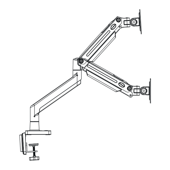
Invision MX900
Ergonomic Gas Assisted
Dual Monitor Arm
Instruction Manual
VESA Compliance 75x75mm & 100x100mm
Recommended Screen Sizes
24"
- 35"
Integrated Cable Management
Load Capacity
2
- 15kg (4.4 - 33lbs)
To receive large format PDF instructions please
email help@InvisionTechnology.co.uk
Tools List:
Important:
1. Check the box contains all the items in the Parts List. Make
sure to remove all internal packaging!
2. Check the screens VESA mounting measurements and
monitor weight.
3. Please read the instructions fully and plan how to mount
your monitor.
4. You may need additional tools: A drill will only be needed
if you are bolting it through a desk, the screwdriver is used
for attaching the monitor screen to the monitor arm.
WARNING!
1
1a. Clamp Installation
1. Secure clamping plates (3) to base (5) with bolts (C) using 4mm Allen key (E) and tighten – see
Diagram 'A'.
2. To set the clamp to the correct height for your desktop/work-surface add the monitor base assembly to the
edge of your desk (use the front of your desk for now if it makes it easier) - see Diagram 'B'.
3. Slide clamp (4) over clamping plate (3). Repeat with the 2nd clamp and clamping plate – see Diagram 'C'.
Diagram 'A'
3
Drill only
needed for
Through Desk
install
4. Measure the thickness of your desk, adjust the height of your clamps so when tightening the clamps have
enough thread on them to secure to desktop – see Diagram 'D'.
5. Secure base assembly to the desktop making sure base is in full contact with the face of the desktop
and cables run through the back of the base – see Diagram 'E'.
Please note:
If you are mounting heavy screens on this monitor arm please evaluate the desktop/ work-surface
you are mounting it to. (Example: Wooden surfaces like chipboard or MDF are compressed high
density boards and are less likely to cause marks or indentations. Natural wooden surfaces are
softer (not compressed) so you may consider adding protection.
Diagram 'D'
20 - 80mm
v20230323
Letters and numbers in ( ) are referred to in the Parts List
Diagram 'B'
5
C
3
2
Diagram 'C'
3
4
Diagram 'E'
Advertisement

Related Manuals for Invision MX900


Summary of Contents for Invision MX900
- Page 1 • If you do not understand the instructions or have any concerns or questions please contact us or a competent installer. • Do not install or assemble if the product or hardware is damaged or missing. If you require replacement parts, please contact us at Invision for assistance.
- Page 2 2 - Monitor Arm Assembly 1b - Through the Desk Installation 1. Locate and position where you want the monitor arm base to sit on your desktop/work-surface. 40mm 1. Take the lower arm (2) and slide the female connector onto the male connection on the monitor minimum is needed from the rear of the desk so the monitor arm base makes full contact with the base (3) making sure it is fully inserted (please ensure you have this the correct way up) - see desktop/work-surface - see Diagram ‘F’.
- Page 3 3 - Attaching Face Plate to Monitor Arm 7. Once the cables are fitted into the cable management trays step 4 (1-6) tidy up the cables - see Diagram ‘S’. 1. Take the face plate (6) and slot the face plate connector between the prongs located on the upper arm (1) making sure the holes are aligned - see Diagram ‘K’.
- Page 4 6 - Using Your Invision MX900 Ergonomic Monitor Arm 8. Rotational Features Setting the tension of the monitor arm to balance the weight of the monitor 1. Your monitor arm allows you to rotate your screen through 360 degrees to view in portrait mode or landscape mode providing the VESA mount on your screen is central.
Need help?
Do you have a question about the MX900 and is the answer not in the manual?
Questions and answers