Advertisement
Table of Contents
- 1 1A - Clamp Base Installation
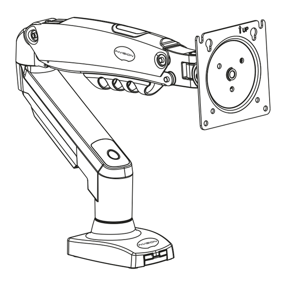
- 2 2 - Monitor Arm Assembly
- 3 1B - through the Desk Installation
- 4 3 - Adding Cables to the Monitor Arms Cable Management
- 5 4 - Mounting the Monitor
- 6 5 - Using Your Invision MX200 Ergonomic Monitor Arm
- 7 6 - Adjusting the Tilt Angle
- 8 7. Rotational Features
- Download this manual
www.InvisionTechnology.co.uk
Parts List:
1
3
4
2
5
A
B
C
4 x
4 x
3 x
M4 x 12
M5 x 12
M6 x 12
D
E
F
G
Butter y nut
Threaded rod
3mm 4mm 5mm
Locking plate
NB
NG P E
E N TE: N T
This product is packed with the faceplate at a 45° angle to fit smaller packaging and reduce environmental waste.
Please rotate the faceplate 45° clockwise before mounting your monitor.
P E
E N TE:
c pl
o
on h
h gh
nc by
no
l n
n
h
yo
c
n
ll b h l
y fo
ov
n
Severe personal injury and property damage can result from improper installation or assembly. Please read the following warning carefully before beginning.
• If you do not understand the instructions or have any concerns or questions, please contact us or a competent installer.
• Do not install or assemble if the product or hardware is damaged or missing. If you require replacement parts, please contact us at Invision for assistance.
• This product fits most VESA compliant 17"-27" LCD/LED monitors to a maximum weight of 9kg (19.8lbs).
• For safe installation, the desk you are mounting it to must support minimum 3 times the weight of the total load (the mount, plus the monitor and all accessories weight).
• Do not use this product for other than the original design purpose.
• This product contains moving parts, please use with caution.
• When installing monitor take care not to damage electrical wiring or power source.
• Important - mains and data cables must be free from twisting and/or shearing.
• The manufacturer disclaims any liability for the modifications, improper installation or installation over the specified weight range. The manufacturer will not be liable for any damages arising from the use of, or
inability to use the product.
• This product is designed for indoor use only, use of this product outdoors could lead to product failure and severe personal injury.
• This product contains a high pressure gas piston This mechanism is not user serviceable and any interference could result in injury or damage. Please dispose of with caution.
• In order to ensure the performance of the gas piston it is recommended to fully extend the arm several times per month.
Lets Get Started!
If you require assistance please contact us at: help@InvisionTechnology.co.uk
MX150
English
Ergonomic Gas Assisted
Monitor Arm
Instruction Manual
VESA Compliance 75x75mm & 100x100mm
Recommended Screen Sizes
17"
- 27"
Integrated Cable Management
Load Capacity 2 - 6.5kg (4.4 - 14.3lbs)
To receive large format PDF instructions
please email help@InvisionTechnology.co.uk
Tools List:
Important:
1. Check the box contains all the items in the Parts List.
2. Check the screens VESA mounting measurements and
monitor weight.
3. Please read the instructions fully and plan how to mount
your monitor.
4. You may need additional tools: A drill will only be needed
if you are bolting it through a desk and a screwdriver is used
to secure the monitor to monitor arm.
T
B
EN
gn n
y n
l l fo c
o
ov
Th
ny y
o co
ho
ny n
n
WARNING!
1
1a - Clamp Base Installation
If you choose to add the USB cable follow steps 1&2, if not continue to Step 3.
1. Remove the 2x screws from the monitor base using a screwdriver and remove the cable cover
- see diagram 'A'.
2. Add in your USB cables and re-attach the cable cover using the screws removed and screwdriver
- see diagram 'B'.
3. Attach the clamp plate (5) to the monitor arm base (3) using 3x M6 bolts (C) with 4mm Allen key (E)
- see diagram 'C'.
Diagram 'A'
4. Take the clamp section (4) and wind the knob out fully to its lowest position - see diagram 'D'.
5. Sit the base of the monitor arm on the desk so the clamp plate is hanging over the edge - see diagram 'E'.
6. Take the clamp section and align the hole to slide over base of clamp plate. Move the clamp section up
to the highest notch possible and then straighten the clamp section so it locks in place on that notch -
see diagram 'F'.
7. Wind knob and tighten to the desk making sure the clamp plate and monitor arm base is pushed up to
the edge of the desk.
Please note: If you are mounting heavy screens on this monitor arm please evaluate the
desktop/work surface you are mounting it to. (Example: Manufactured wooden surfaces like
chipboard or MDF are compressed high density boards and are less likely to cause marks or
indentations. Natural wooden surfaces are softer (not compressed) so you may consider
adding protection.
45
Diagram 'D'
v20220926
Letters and numbers in ( ) are referred to in the Parts List
Diagram 'B'
USB cables
not supplied
Diagram 'E'
2
Diagram 'C'
Diagram 'F'
Advertisement
Table of Contents

Related Manuals for Invision MX150


Summary of Contents for Invision MX150
- Page 1 • If you do not understand the instructions or have any concerns or questions, please contact us or a competent installer. • Do not install or assemble if the product or hardware is damaged or missing. If you require replacement parts, please contact us at Invision for assistance.
- Page 2 2 - Monitor Arm Assembly 1b - Through the Desk Installation 1. Take the lower arm (2) and slot the male connector into the female connection on the monitor base (3) 1. Locate and position where you want the monitor arm base to sit on your desktop/work surface. 40mm making sure it is fully inserted (please ensure you have this the correct way up) - see Diagram ‘J’.
- Page 3 3 - Adding Cables to the Monitor Arms Cable Management 4 - Mounting the Monitor Make sure there is enough slack on your cables so the product can function without pulling 1. Check the monitors VESA by measuring the distance between the mounting holes on the back of the or stretching them.
- Page 4 5 - Using Your Invision MX200 Ergonomic Monitor Arm 7. Rotational Features Setting the tension of the monitor arm to balance the weight of the monitor 1. Your monitor arm allows you to rotate your screen through 360˚ to view in portrait mode or landscape mode providing the VESA mount on your screen is central.
Need help?
Do you have a question about the MX150 and is the answer not in the manual?
Questions and answers