Table of Contents
Advertisement
Quick Links
www.InvisionTechnology.co.uk
Parts List:
First things first: Check the box contains all the items in the parts list above.
Check VESA Compatibility: Please check the VESA measurements before drilling any holes (to check your
TVs VESA, measure distance between mounting holes on back of TV).
Check the weight of your TV: You may need an extra person on hand to help!
Y
ou will need a few additional tools: A drill & 10mm masonry drill bit or 4mm wood drill bit, depending on the
fixing surface, safety glasses, a large Phillips screw driver, a 12mm spanner for the wall fixings (a 12mm socket
set is even better) a pencil and a spirit level.
Please wear safety glasses before using your drill – if you have any doubts installing this item please consult
your retailer or an experienced installer.
Now please read the instructions fully and plan how to mount your bracket! - As with most single arm
cantilevers, note the centre line of the TV will be 127mm (5") offset to the wall fixing centre line.
Severe personal injury and property damage can result from improper installation or assembly. Please read the following warning carefully before beginning.
•
Product must be installed by a professional or competent installer.
•
If you do not understand the instructions or have any concerns or questions please contact us or a competent installer.
•
Do not install or assemble if the product or hardware is damaged or missing. If you require replacement parts, please contact us at Invision for assistance.
•
This product fits most 24" - 60" LCD/plasma screen, maximum weight of LCD/plasma screen 36.2kg (80lbs).
•
This product has been designed for use on vertical walls constructed of wood studs (minimum 2" x 4" / 51mm x 102mm) or masonry (solid concrete 2000 PSI density minimum).
•
For safe installation, the wall you are mounting on must support minimum 3 times the weight of the total load (the TV bracket, the TV and all accessories).
•
Do not use this product for any other application than the original design purpose.
•
This product contains moving parts, please use with caution.
•
When installing take care not to damage electrical wiring or power source.
•
The manufacturer will bear no responsibility for mounting to the wall, or incidental or consequential damages arising there from.
•
The manufacturer disclaims any liability for the modifications, improper installation or installation over the specified weight range.
•
The manufacturer will not be liable for any damages arising from the use of, or inability to use the product.
Lets Get Started!
If you require assistance please contact us at: help@InvisionTechnology.co.uk
English
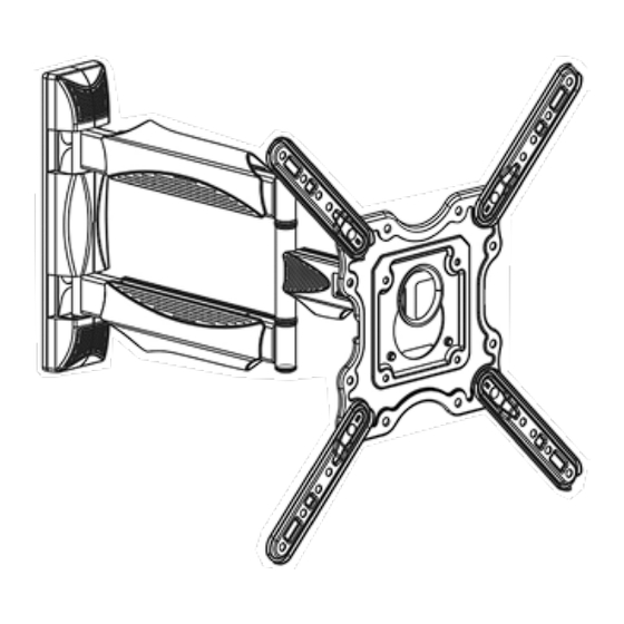
Invision HDTV-E
Single Arm TV Wall Mount
Instruction Manual
VESA Compliance 100x100mm - 400x400mm
Recommended Screen Sizes 24" - 60"
Integrated Cable Management
Load Capacity 36.2kg (80lbs)
To receive large format PDF instructions please email:
help@InvisionTechnology.co.uk
Tools List:
(Not for use with wall fixings)
WARNING!
1
Step 1 (Unboxing)
Open the box, take out TV bracket then remove
the wall fixing plate plastic covers (Diagram 'A').
Straighten out TV bracket as per diagram.
Remove the bottom 2x M6 bolts (Diagram 'B')
using spanner K (provided) which secures the TV
mounting plate to bracket arm (do NOT remove
the top 2 locking nuts that adjust the tilt).
Diagram 'A'
Step 2a (VESA TV Fixings)
Lay TV face down on flat surface to access the 4 VESA fixing
points. Position TV mounting plate 'A.' onto back of the TV with
flat side facing TV & align to the 4 VESA fixing points (use
relevant bolts, washers & spacers as per diagram).
Plate 'A' covers TVs with VESA 100x100mm to 200x200mm.
For VESA sizes above 200x200mm see Step 2b below.
Step 2b
Measure and arrange the 4 VESA arms to align with your TVs fixing points see diagrams 'A' & 'B'.
Attach the 4 VESA arms to the main TV fixing plate as in diagrams 'C' using the black nuts and bolts
N & O ensuring the square shank at the end of the thread locks in the square hole on the VESA arm.
Each arm also has a raised notch which locks into the small rectangle hole on the main TV fixing plate
(this ensures the VESA arm cannot move out of position).
Now attach the assembly to the back of your TV as in diagram 'D' and select the correct bolts and
washers to match the hole depth. Spacers can be used to adjust the length of your bolts if required.
Please contact us for further VESA arrangements not shown below.
Diagram 'A'
v20220209
Diagram 'B'
K
Spacers and washers can be used in
front or behind TV mounting assembly.
Use bolts (A - J) to secure
mounting assembly to TV.
Spacers and washers can be used in
front or behind TV mounting assembly.
Diagram 'B'
Diagram 'C'
2
Use bolts (A - J) to secure
mounting assembly to TV.
Diagram 'D'
Advertisement
Table of Contents

Related Manuals for Invision HDTV-E


Summary of Contents for Invision HDTV-E
- Page 1 If you do not understand the instructions or have any concerns or questions please contact us or a competent installer. • Do not install or assemble if the product or hardware is damaged or missing. If you require replacement parts, please contact us at Invision for assistance. •...
- Page 2 All our products carry our Compatibility Promise. Your installation is now complete - Sit back & enjoy! To activate your 25 year warranty please email your Name, Order Number and Product Reference HDTV-E to warranty@InvisionTechnology.co.uk...
Need help?
Do you have a question about the HDTV-E and is the answer not in the manual?
Questions and answers