
Related Manuals for MULTILANE ML BERT Series


Summary of Contents for MULTILANE ML BERT Series
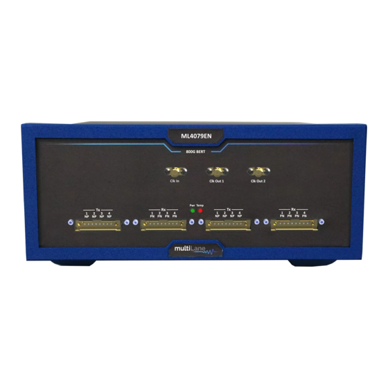
- Page 1 ML4079EN User Guide ThunderBERT User Guide ML BERT Series: ML4079EN Installation | Connection | Calibration| Measurement User Manual Revision, June 2023...
-
Page 2: Notices
Copyright © MultiLane Inc. All rights reserved. Licensed To Avoid Fire or Personal Injury software products are owned by MultiLane Inc. or its suppliers and are protected by United States copyright Use Proper Power Cord. Only use the power cord specified laws and international treaty provisions. -
Page 3: Table Of Contents
Contents Notices ..............................2 List Of Acronyms ............................ 4 Introduction ............................5 GUI Introduction ............................ 6 Installation ..............................6 Connecting to the Instrument .......................... 7 Launching the GUI ............................8 GUI Overview ..............................8 BERT Configurations ............................9 GUI Navigation ............................ 11 Instrument Control ............................ -
Page 4: List Of Acronyms
List Of Acronyms Acronym Definition Bandwidth BERT Bit Error Rate Tester Conf Configuration Device Under Test Forward Error Correction Firmware Gigabaud Gbps Gigabits per Second Graphical User Interface Hardware Inter-symbol Interference JTOL Jitter Tolerance Non-Return to Zero PAM4 Pulse Amplitude Modulation (4-level) Signal Integrity Signal-to-Noise Ratio Simulation... -
Page 5: Introduction
The brand new ThunderBERT GUI provides you with an intuitive and comprehensive tool to validate your designs. In this upgraded implementation of our BERT user guide, MultiLane provides a fully revised and unified manual for the ML BERT series compatible with the ThunderBERT GUI. -
Page 6: Gui Introduction
GUI Introduction To install and start using the ThunderBERT interface for the first time, follow this step-by-step installation guide (with pictures) below: 1. Run the ThunderBERT setup file. 2. Install ThunderBERT. 3. Connect the ML BERT to the local network. 4. -
Page 7: Connecting To The Instrument
Connecting to the Instrument To connect to the instrument, follow this sequence of steps: ▪ Install the ThunderBERT GUI software. ▪ Connect the power cable to the power jack of the BERT and plug it into an AC outlet. The power cable is already included in the package accessories. ▪... -
Page 8: Launching The Gui
Launching the GUI After establishing connection to the BERT, the GUI is initialized immediately, and all the BERT features are ready for use. The general display of the ThunderBERT GUI will appear and you can commence testing. Figure 5: General GUI Display (ML4079EN) Figure 4: General GUI Display (ML4079EN) GUI Overview ThunderBERT provides end users with the ability to navigate and configure instruments from the ML... -
Page 9: Bert Configurations
BERT Configurations This section is used to parameterize BERT measurements and to control the TX/RX configurators of each channel in addition to clock rate and other common BERT settings. About Window Title Tab Common BERT Tab Tx Control Section Clock Configurations Figure 6: BERT Control Tab ▪... - Page 10 o Clock-In ▪ RX-side Control Section Tab contains: o RX invert, RX pattern selection and RX diagnostics o Equalization block...
-
Page 11: Gui Navigation
GUI Navigation Instrument Control Title Tab Figure 8: Title Tab ▪ Displays general information of the BERT (BERT PN, instrument IP, instrument temperature). ▪ The device tab where all board details are displayed (Figure 9). ▪ Close button: disconnect from the BERT and close GUI instance (Figure 10). Figure 9: Device Tab Figure 10: Disconnect Popup Window... - Page 12 From this tab, select/configure to control the following features: ▪ Specify the Baud rate (Figure 13) ▪ Specify the signal modulation type: NRZ/PAM4 (if available/supported) (Figure 14) ▪ Select the 3 or 7 taps FIR filter mode ▪ Enable/Disable the Noise Injection ▪...
-
Page 13: Tx Control
Tx Control TX Control in optimal Mode TX channel settings can be controlled individually. A display window reflecting all the enabled features and the applied TX settings per channel is displayed after clicking on each TX channel tab (Figure 16) ▪... - Page 14 To insert Errors: ▪ Enable Error Insertion mode (the green color indicates that error insertion feature is enabled). ▪ Specify the Error Insertion Rate. ▪ Click on the Update button to apply changes. Figure 16: Error Insertion in Optimal Mode...
-
Page 15: Tx Control In Advanced Mode
Tx Control in Advanced Mode While operating in Advanced Mode, you can fine-tune the transmitter signal with high granularity. You will be able to specify the following TX settings and parameters: ▪ TX Pattern: Supported TX patterns are all available in the dropdown list, depending on the BERT model in use. - Page 16 Optimal configurations and calibration are only available in 3-tap mode. The Channel NOTES: Emulation feature is only supported in 7-tap mode. ▪ Channel emulation. To emulate channel loss, start by clicking the emulation button. When enabled, the emulation button will turn to green. You can insert the magnitude of the loss at the Nyquist frequency (half of the configured baud rate) in decibels.
-
Page 17: Rx Control
Apply To all Channels Option This option is used for the TX and RX settings, and transceiver control if available. When selected, it applies the configuration of the current channel to all BERT channels. For example, pressing “Apply to all” on the TX window will apply all TX configurations displayed in this window to every other channel. -
Page 18: Rx Diagnostics
The RX channel tab employs green shading to highlight the enabled RX features (RX polarity inversion, RC, DFE, MPICAN). Figure 23: Rx Side with Different EQ Types Enabled Rx Diagnostics To access the RX diagnostics graph section, select the RX button found in the RX configuration window of each channel After pressing the button, RX diagnostics button is shaded in green, and a graph section will appear as shown in Figure 23. -
Page 19: Clock Configuration
▪ You can save the graphs with the save button in the upper righthand corner of the window. NOTES: ▪ You also have the option to view all the channels at once for selected measurements Clock Configuration With ThunderBERT, you can choose between different clock configuration options: ▪... -
Page 20: Supported Measurements
Supported Measurements The ThunderBERT platform provides comprehensive control of all supported measurements including BER, FEC, SER and Rx Diagnostics Measurement Controls Control Definition Start and Stop BER, FEC, and SER measurements RX diagnostics: RX FFE taps, SNR, and Histogram Control Capture histogram and update error insertion rate Save RX FFE taps, SNR values, histogram captures Save and Load FFE taps, Save and Load BERT settings... -
Page 21: Generic Measurements
Generic Measurements You can execute BER measurements according to the channels you select. While the test is running, you can change the X and Y axis according to the supported graph combinations. During a direct loopback test, to avoid any damage on the Rx side always make sure to adjust the Tx amplitude swing to a maximum of 800mV You have the choice to measure/visualize different options such as: ▪... - Page 22 Instant and accumulated measurements can be displayed simultaneously in the details panel and on the graph. In addition, you can navigate through the measurement behavior at any past time in the test using History Navigation in the details panel at 100 ms intervals. Figure 29: Measurement Display Graph Autoscale –...
- Page 23 ▪ PAM4 Measurements: X axis Y axis X axis Y axis Real Time BER Real Time BER Instant BER Instant BER Instant Error Count Instant Error Count Accumulated Error Count Accumulated Error Count Real Time BER MSB Real Time BER MSB Real Time BER LSB Real Time BER LSB Bit Count...
- Page 24 After selecting the desired graph configuration, data will be plotted instantly (make sure to choose the desired channel and click on the Start button). You can access the instant and accumulated measurements data using the BER measurements table. You can switch from graph to table measurements with no test interruptions. You can save the table of result onto your desktop using the save button.
-
Page 25: Platform Specific Measurements
Platform Specific Measurements MultiLane offers the new ML4079EN with Real Hardware FEC and stress testing features such as Jitter injection in both FM and PM Mode, Single Frequency, and IEEE JTOL in addition to random, burst noise injection and automated ITOL Testing... - Page 26 After you have applied your LK, the BERT should be disconnected, and power cycled. Full features will then be accessible and ready to use. You will be notified if a wrong LK is entered (figure 36). The GUI will disconnect directly if a wrong LK is entered four times consecutively (figure 37) Figure 36: Number of Authorized Attempts Figure 35: Wrong License Key...
-
Page 27: Jitter Injection
Jitter Injection The ML4079EN includes 2 types of jitter injection. The first one is manual jitter injection in both FM and PM modes. The other one is the JTOL option including both IEEE JTOL and Single Frequency JTOL All jitter options are enabled after installing the license A. - Page 28 Figure 38: FM RJ Enabled 2) Phase Modulation: For the Phase Modulation PM Jitter injection, you can choose between Sinusoidal Jitter (SJ), Random Jitter (RJ), Bounded Uncorrelated Jitter (BUJ) or all of them. ▪ SJ Enable: Click on the PM Icon. When enabled, this icon will turn green To enable PM SJ, click on the SJ Checkbox, select the Frequency, use the slider to adjust the jitter amplitude, Adjust the PM Shift slider to the middle and click on Set...
- Page 29 ▪ RJ Enable: Click on PM Icon. When enabled, this icon will turn green To Enable PM RJ, Click on RJ Checkbox, use the slider to adjust the jitter amplitude and click on Set, Adjust the PM Shift slider to the middle and click on Set A recommended PM Shift value is around 1700.
- Page 30 B. JTOL: In addition to the manual jitter injection, the ML4079EN Offers an automated Jitter Tolerance Test. With this feature, the user can test it’s DUT based on IEEE 802.3 Specifications using the IEEE JTOL. In addition, the user can use the single frequency JTOL to test his DUT at one frequency and between 2 amplitude values Also, the JTOL options, includes Margin calculations and a save as CSV File option 1) IEEE JTOL:...
- Page 31 Figure 42: IEEE JTOL Options A: IEEE Specification depending on selected line rate – B: User’s Target BER based on which the pass/fail verdict will be done – C: BER Time: in seconds – D: Warning message if the IEEE Spec chosen and the line rate don’t match –...
- Page 32 Figure 44: Table Option A: Test Time (s) – B: Jitter Injection Amplitude (UI) – C: Test Frequency (KHz) – D: BER result – E: JTOL Result: Pass/Fail after comparing the BER Result to Target BER – F: JTOL Margin 2) Single Frequency JTOL: Click on the JTOL Tap, Select Single Frequency, Chose the SJ Frequency you want to test on, Select your Start and Finish Point as Jitter Injection Amplitude in steps...
- Page 33 Figure 45: Single Frequency JTOL A: Selected SJ Frequency – B: Starting Test Point - C: Final Test Point – D: to help identify the number of test points – E: Target BER to determine the Pass/Fail Points – F: BER Test Duration G: Selected Channel for this test...
- Page 34 C) SJ Calibration: Sinusoidal Jitter (SJ) is calibrated in both modes FM and PM The factory calibration is done at 10 frequencies as per IEEE 802.3 Requirements: 40, 100, 400, 1000, 1330, 2500, 7000, 10000 and 12000KHz In addition to the factory calibration, the ML4079EN enables the user to do his own calibration To note that, when in IEEE JTOL Mode the factory calibration shall be used a) Calibration Setup:...
- Page 35 b) Calibration Example: FM Mode 100KHz: 1) Raw Data Collection, copy the excel values to a wordpad file .txt Raw Data Equivalent from DSO BERT Slider (Steps) (ps) 32.8 38.2 39.8 41.4 43.2 44.8 46.4 47.8 52.4 54.2 57.4 62.2 64.2 66.8 1000...
- Page 36 1) Go to Matlab: load the txt file, change the x,y dimensions and click on Run: Figure 46: Raw Data and Data after Fitting 2) Verify that the fitting data is accurate and remove all saturated points 3) Go to Matlab workspace, “a” and copy the values 4) Go to Matlab workspace, “data”, copy the min and max values in ps: the values shall be integer...
- Page 37 5) After Finalizing the other Frequencies, a,b,c and d, min and max are copied to the Jitter Calibration GUI, click on save frequencies, save all and save to file if you want to save the calibration values to be read later on...
-
Page 38: Noise Injection
Noise Injection: With the new ML4079EN, the user can now inject Random or Burst Noise and benefit from the automated interference tolerance test (ITOL). In addition, to emulating real life crosstalk scenarios the ML4079EN supports shallow loopback testing Random Noise Scenarios can be configured on each 2 channels independently 1) Random Noise: To enable Random Noise, click on the Noise Icon located at the top configuration bar, the click on Enable Noise... - Page 39 3) Automated Interference Tolerance (ITOL): Figure 49: ITOL Tab A: Target BER Based on which the Pass/Fail Verdict will be issued – B: BER Test Time at each point – C: Test is done on each 2 consecutive channels – D: test time – E: BER Value –...
- Page 40 4) Shallow Loopback: The shallow loopback function works with a variety of traffic types including unframed PRBS, framed ethernet and FEC traffic. The following figure depicts a ML4039EN accepting traffic from an external 400G switch, looping the traffic back internally and re-transmitting it back to the RX side of the host.
-
Page 41: Real Hardware Fec Measurements
Real Hardware FEC Measurements. After entering an applicable FEC license code into ThunderBERT, enable the FEC measurements from the drop-down list and then press apply. Once enabled, the FEC button will become green and display the FEC type selected. Figure 51: Enabling FEC... - Page 42 When FEC is enabled, you can change the X and Y axes to the supported graph combinations where instant and accumulated bit counts are supported and can see the results of the measurements in the details section. SER measurements are also supported in FEC mode; corrected codewords with symbol error distribution are displayed.
- Page 43 To enable measurements, select a value for both the X and Y axes*. Different options for the X axis selection are supported, but only one can be selected per measurement, while more than one Y axis can be selected and displayed simultaneously. The scale of each Y axis selected will be displayed on the left of the graph.
- Page 44 There are three measurement blocks for SER: 1. Instant Codeword Symbol: the symbol error rate distribution for the link under test in a specific 100 ms window. Refreshes 10 times per second. 2. Accumulated Codeword Symbol: the sum of total symbol error rate distribution for the link under test, accumulating from t =0.
- Page 45 X axis Y axis X axis Y axis Instant FEC corrected Bit Rate Instant FEC corrected Bit Rate Instant Corrected One Count Instant Corrected One Count Instant Corrected Zero Count Instant Corrected Zero Count Instant Corrected Codeword Count Instant Corrected Codeword Count Instant Uncorrected Codeword Count Instant Uncorrected Codeword Count Instant Uncorrected Codeword Error Rate...
- Page 46 X axis Y axis X axis Y axis Instant FEC corrected Bit Rate Instant FEC corrected Bit Rate Instant Corrected One Count Instant Corrected One Count Instant Corrected Zero Count Instant Corrected Zero Count Instant Corrected Codeword Count Instant Corrected Codeword Count Instant Processed Codeword Count Instant Processed Codeword Count Instant Uncorrected Codeword Count...
-
Page 47: Appendix 1- Using Ml Instrument Manager To Enable Dhcp
Appendix 1- Using ML Instrument Manager to enable DHCP MultiLane created a new platform “ML Instrument Manager”, to help the user to change the Instrument’s IP address and to enable the use of DHCP. To access all the ML4079ENs available, the user has 2 options, to connect the instrument to his PC via... - Page 48 After completing these steps, a device driver installation wizard will appear: 1) Click on Next 2) After verifying that the drivers were successfully installed, click on Finish 3) Click on the “Launch MLInstrumentManager” checkbox and press on Finish Figure 59: ML Instrument Manager Device Driver Installation Wizard...
- Page 49 B) ML InstrumentManager Usage : Ethernet Connection 1) Make sure the PC is connected via Ethernet/USB 2) Click on Scan ML Devices at the TOP of the GUI 3) The instrument you are using will be shown with all its information, in addition to the Ethernet or USB Icon depending in the used mode: 4) To change the IP, Check the Ethernet Settings and click on Edit 5) To enable DHCP, turn the DHCP Mode Tuggle On, then click on Change and power cycle...
- Page 50 Ethernet Icon USB Icon...
-
Page 51: Appendix 2 - Adding A Bert To The Network
Appendix 2 – Adding a BERT to the Network To create a local network connection, please follow these steps: ▪ Create a local network connection between the laptop and the BERT using Internet Protocol Version 4 (TCP/IPv4). o Open Control Panel and choose Network and Internet. o Open Network and Sharing Center. - Page 52 ▪ Add a similar IP Address that shares a subnet with the instrument IP in the Advanced tab. This will be used to ping the instrument once the IP Address is changed to match that of the network. ▪ Connect the laptop directly to the BERT using an Ethernet cable.
-
Page 53: Appendix 3 - Changing The Ip Address To Suit A Corporate Network
Appendix 3 – Changing the IP Address to Suit a Corporate Network MultiLane does not recommend changing the IP address of the BERT instrument. However, this appendix will detail the steps for each operation. Before starting the IP address change operation, please contact your IT department/support. You should be provided an available IP on the network. - Page 54 Ethernet Configuration Windows, when the Device is Connected and Powered On (Online, Left Figure) and Disconnected (Offline, Right Figure).
-
Page 55: Changing The Ip Address Using Ml Ipchanger
Changing the IP Address Using ML IPChanger Before changing the IP address using the ML IPChanger tool, make sure there is a local network between the unit and the PC using one single Ethernet cable with RJ45 connector at each end. Make sure that the unit is powered on and has established a ping between the current factory IP and your PC by creating a Local Network Connection.
Need help?
Do you have a question about the ML BERT Series and is the answer not in the manual?
Questions and answers
Is there a command that allows me to load a previously saved configuration file onto an ML BERT?