
Related Manuals for MULTILANE ML BERT Series

Summary of Contents for MULTILANE ML BERT Series
- Page 1 USER GUIDE | ML BERT Series Installation | Connection | Calibration| Measurement User Manual Revision 1.1.0, July 2021 ML4039B – ML4054B – ML4039D – ML4079D – ML4039E/EN – ML4079E/EN...
-
Page 2: Notices
Copyright © MultiLane Inc. All rights reserved. Licensed To Avoid Fire or Personal Injury software products are owned by MultiLane Inc. or its suppliers and are protected by United States copyright Use Proper Power Cord. Only use the power cord specified laws and international treaty provisions. -
Page 3: Table Of Contents
Table of Contents Notices ............................. 2 Table of Contents ..........................3 Revision Control ..........................4 List of Acronyms ..........................5 Introduction ............................6 GUI Introduction ..........................7 Installation ................................ 7 Connecting to the Instrument ........................... 8 Launching the GUI ............................. 9 GUI Overview .............................. -
Page 4: Revision Control
Revision Control Revision number Description Release Date ▪ 11/25/2020 1.0.0 Initial Release ▪ Added new TB Features: measurement tables, multi-channel 07/22/2021 1.1.0 support, new FEC measurements (BER, SER) ▪ Adapter Compliance Testing using ML4054B... -
Page 5: List Of Acronyms
List of Acronyms Acronym Definition Bandwidth BERT Bit Error Rate Tester Conf Configuration Device Under Test Forward Error Correction Firmware Gigabaud Gbps Gigabits per Second Graphical User Interface Hardware Inter-symbol Interference JTOL Jitter Tolerance Non-Return to Zero PAM4 Pulse Amplitude Modulation (4-level) Signal Integrity Signal-to-Noise Ratio Simulation... -
Page 6: Introduction
The brand new ThunderBERT GUI provides you with an intuitive and comprehensive tool to validate your designs. In this upgraded implementation of our BERT user guide, MultiLane provides a fully revised and unified manual for the ML BERT series compatible with the ThunderBERT GUI. -
Page 7: Gui Introduction
GUI Introduction To install and start using the ThunderBERT interface for the first time, follow this step-by-step installation guide (with pictures) below: 1. Run the ThunderBERT setup file. 2. Install ThunderBERT. 3. Connect the ML BERT to the local network. 4. -
Page 8: Connecting To The Instrument
Connecting to the Instrument To connect to the instrument, follow this sequence of steps: ▪ Install the ThunderBERT GUI software. ▪ Connect the power cable to the power jack of the BERT and plug it into an AC outlet. The power cable is already included in the package accessories. ▪... -
Page 9: Launching The Gui
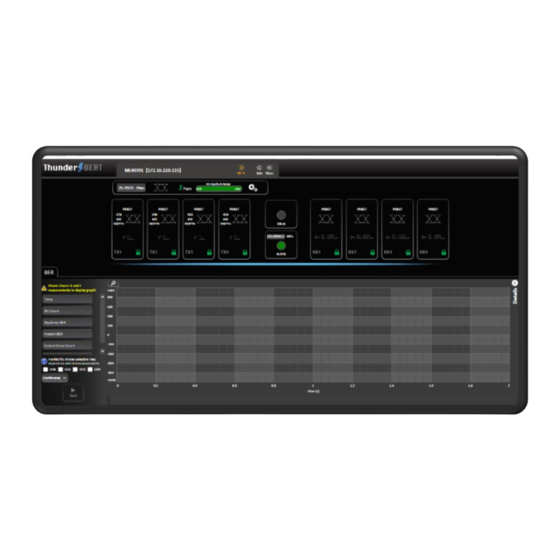
Launching the GUI After establishing connection to the BERT, the GUI is initialized immediately, and all the BERT features are ready for use. The general display of the ThunderBERT GUI will appear and you can commence testing. Figure 4: General GUI display (ML4039E) GUI Overview ThunderBERT provides end users with the ability to navigate and configure instruments from the ML BERT product family. -
Page 10: Bert Configurations
BERT Configurations This section is used to parameterize BERT measurements and to control the TX/RX configurators of each channel in addition to clock rate and other common BERT settings. Figure 6: BERT control tab ▪ About Window (Figure 7) will give you access to the necessary information about the product including: SW and API versions and Release Note A link to this User Guide... -
Page 11: Gui Navigation
GUI Navigation Instrument Control Title Tab Figure 8: Title tab ▪ Displays general information of the BERT (BERT PN, instrument IP, instrument temperature). ▪ The device tab where all board details are displayed (Figure 9). ▪ Close button: disconnect from the BERT and close GUI instance (Figure 10). Figure 10: Disconnect popup window Figure 9: Device tab BERT Settings Tab... -
Page 12: Tx Control
From this tab, select/configure to control the following features: ▪ Specify the Baud rate. ▪ Specify the signal modulation type: NRZ/PAM4 (if available/supported). ▪ Enable/Disable the FEC feature. ▪ Check the Rx amplitude range supported by the error detector. ▪ Select the 3 or 7 taps FIR filter mode. -
Page 13: Tx Control In Advanced Mode
▪ Enable/Disable TX control for each channel (TX ON/OFF). Once turned off, the control of TX settings is disabled: channel control is locked from any selections, and TX output is turned off (Figure 17). ▪ Specify the TX signal pattern. The supported TX patterns are all available in the dropdown list, depending on the BERT model in use. - Page 14 ▪ TX Pattern: Supported TX patterns are all available in the dropdown list, depending on the BERT model in use. ▪ FFE Taps: Tap control offers the following on TX: o Scaling between 60% and 120% o 3 FFE taps (in 3-tap mode) and FIR filter 7 taps (in 7-tap mode).
- Page 15 Optimal configurations and calibration are only available in 3-tap mode. The Channel NOTES: Emulation feature is only supported in 7-tap mode. ▪ Channel emulation. To emulate channel loss, start by clicking the emulation button. When enabled, the emulation button will turn to green. You can insert the magnitude of the loss at the Nyquist frequency (half of the configured baud rate) in decibels.
-
Page 16: Rx Control
Apply to all channels option This option is used for the TX and RX settings, and transceiver control if available. When selected, it applies the configuration of the current channel to all BERT channels. For example, pressing “Apply to all” on the TX window will apply all TX configurations displayed in this window to every other channel. -
Page 17: Rx Diagnostics
The RX channel tab employs green shading to highlight the enabled RX features (RX polarity inversion, RC, LDEQ, MPICAN). Rx Diagnostics Figure 27: RX side with different EQ types enabled To access the RX diagnostics graph section, select the RX button found in the RX configuration window of each channel. -
Page 18: Clock Configuration
(JTOL) testing for DUTs. First, set the clock mode to be Clk-In mode per the previous section. MultiLane offers the ML407-PAM as a jittered clock source, more information on this solution can be found on the MultiLane website. -
Page 19: Supported Measurements
Supported Measurements The ThunderBERT platform provides comprehensive control of all supported measurements including BER, FEC, SER, and RX diagnostics. Measurement Controls Table 1: Measurement Controls Control Definition Start and Stop BER, FEC, and SER measurements RX diagnostics: RX FFE taps, SNR, and Histogram Control Capture histogram and update error insertion rate Save RX FFE taps, SNR values, histogram captures Save and Load FFE taps, Save and Load BERT settings... - Page 20 Supported measurements are grouped in the following table: Table 2: Supported BER Measurements Instant Measurements Accumulated Measurements Instant BER Real Time BER Instant Error Count Accumulate Error Count Instant BER MSB Real Time BER MSB Instant BER LSB Real Time LSB Instant Error Count MSB Accumulated Count MSB Instant Error Count LSB...
- Page 21 A display of supported NRZ/PAM4 BER graph combinations is shown below depending on the measurement type: ▪ PAM 4 Measurements Table 3: PAM4 BER Graph Combinations X axis Y axis X axis Y axis Real Time BER Real Time BER Instant BER Instant BER Instant Error Count...
-
Page 22: Platform Specific Measurements
Figure 36-1: Error tracking vs. time Platform Specific Measurements MultiLane offers both emulated and real hardware FEC-supporting devices. Available FEC measurements depend on the HW revisions and the type of BERT in use. In this section, the supported specific measurements will be detailed. -
Page 23: Real Hardware Fec Measurements
If the LK is valid, another pop-up window will appear, informing you that the LK has been applied. Figure 39: License key added Figure 40: FEC features enabled After you have applied your LK, the BERT should be disconnected and power cycled. Full hardware FEC features will then be accessible and ready to use. - Page 24 When FEC is enabled, you can change the X and Y axes to the supported graph combinations where instant and accumulated bit counts are supported and can see the results of the measurements in the details section. SER measurements are also supported in FEC mode; corrected codewords with symbol error distribution are displayed.
- Page 25 To enable measurements, select a value for both the X and Y axes*. Different options for the X axis selection are supported, but only one can be selected per measurement, while more than one Y axis can be selected and displayed simultaneously. The scale of each Y axis selected will be displayed on the left of the graph.
- Page 26 There are three measurement blocks for SER: 1. Instant Codeword Symbol: the symbol error rate distribution for the link under test in a specific 100 ms window. Refreshes 10 times per second. 2. Accumulated Codeword Symbol: the sum of total symbol error rate distribution for the link under test, accumulating from t =0.
- Page 27 X axis Y axis X axis Y axis Instant FEC corrected Bit Rate Instant FEC corrected Bit Rate Instant Corrected One Count Instant Corrected One Count Instant Corrected Zero Count Instant Corrected Zero Count Instant Corrected Codeword Count Instant Corrected Codeword Count Instant Uncorrected Codeword Count Instant Uncorrected Codeword Count Instant Uncorrected Codeword Error Rate...
-
Page 28: Emulated Fec Measurements
X axis Y axis X axis Y axis Instant FEC corrected Bit Rate Instant FEC corrected Bit Rate Instant Corrected One Count Instant Corrected One Count Instant Corrected Zero Count Instant Corrected Zero Count Instant Corrected Codeword Count Instant Corrected Codeword Count Instant Processed Codeword Count Instant Processed Codeword Count Instant Uncorrected Codeword Count... -
Page 29: Noise Injection And Shallow Loopback Measurements
Table 7: Instant and Accumulated Emulated FEC Measurements Instant and Accumulated Figure 10: About Window Measurement Description Measurement Selection Raw and unframed ratio of incorrect bits (Bit Errors/Total Bits) on a channel- Pre-FEC Bit Error Rate by-channel basis. Total number of bit errors remaining after emulated bit correction divided Post-FEC Bit Error Rate by the total number of received bits. - Page 30 Figure 51: PAM4 eye diagram with and without noise injection applied Noise settings can be configured on each channel independently. Figure 12: About Window To enable Noise Injection: ▪ Enable noise insertion mode via the button in the top configuration bar. ▪...
-
Page 31: Host Interface For Module Management
Host Interface for Module Management Supported on the ML4054B. Module Management Interface The ML4054B features an embedded module adapter which integrates module management features into the ThunderBERT GUI itself. Adapter DDM Tab Measurements Tab Transceiver/CMIS window Figure 53: Module management tabs using ThunderBERT GUI DDM Tab Figure 14: About Window The DDM tab (Digital Diagnostic Monitoring) depicts the diagnostic readout of the populated... - Page 32 Alarms The DDM button itself reflects the state of the module to monitor. The button changes its color according to the state of parameters: • indicates all the values are in normal range of operation. • indicates that at least one warning is issued. •...
- Page 33 ▪ The populated module should be CMIS3.0 or CMIS4.0 compliant in order to leverage the NOTES: Transceiver menu (TB v1.5.0). In case of a lack of CMIS compliance, the CMIS button turns red and the displayed measurements might be erroneous due to module register mismatch.
- Page 34 ▪ R/W Tab gives you access to MSA table banks. You can read or write the desired values under the Single Register tab. The data must be written in hexadecimal (HEX) format only. Figure 58: Read/write tab of CMIS window When writing/reading data, the specified address should be less than 128 in the “LowMem”...
- Page 35 Adapter Measurements Bar The Adapter Measurements Tab displays the V of the module’s alimentation signal, of the transmission (TX) and the received (RX) signals. Figure 62: Adapter measurements ML4054B Adapter The built-in adapter of the ML4054 presents useful pins so you can directly access and control Figure 23: About Window adapter features.
- Page 36 External Power When external power mode is enabled, the adapter should be powered using the external power Connector pins (supply voltage should be 3.3 V) Serial Clock (SCL) Input Pin when operating in External I2C Mode. Serial Data (SDA) Input Pin when operating in External I2C Mode. Ground Pin.
- Page 37 ▪ If you attempt to enter internal I2C mode with the jumper still on the HW_I2C pin, a NOTES: warning message will pop up (Figure 66). ▪ NOTE: If the jumper is still on the HW_I2C pin, the adapter will operate in the external I2C mode regardless the chosen mode on the GUI.
-
Page 38: Bert Characteristics
BERT Characteristics The MultiLane BERT family is diverse enough to cover a wide array of baud rates and specific applications. The key distinguishing characteristics of all ThunderBERT-compatible platforms can be found below. Detailed product specifications are available in the BERT section of the website here. -
Page 39: Appendix 1 - Adding A Bert To The Network
Appendix 1 – Adding a BERT to the Network To create a local network connection, please follow these steps: ▪ Create a local network connection between the laptop and the BERT using Internet Protocol Version 4 (TCP/IPv4). o Open Control Panel and choose Network and Internet. o Open Network and Sharing Center. - Page 40 ▪ Add a similar IP Address that shares a subnet with the instrument IP in the Advanced tab. This will be used to ping the instrument once the IP Address is changed to match that of the network. ▪ Connect the laptop directly to the BERT using an Ethernet cable.
-
Page 41: Appendix 2 - Changing The Ip Address To Suit A Corporate Network
Appendix 2 – Changing the IP Address to Suit a Corporate Network MultiLane does not recommend changing the IP address of the BERT instrument. However, this appendix will detail the steps for each operation. Before starting the IP address change operation, please contact your IT department/support. You should be provided an available IP on the network. -
Page 42: Changing The Ip Address Using Ml Ipchanger
Ethernet configuration windows, when the device is connected and powered on (online, left figure) and disconnected (offline, right figure). Changing the IP Address Using ML IPChanger Before changing the IP address using the ML IPChanger tool, make sure there is a local network between the unit and the PC using one single Ethernet cable with RJ45 connector at each end. -
Page 43: Appendix 3 - Firmware Upgrade: Step By Step Guide
Appendix 3 – Firmware Upgrade: Step by Step Guide To upgrade the firmware, follow these next steps carefully. Before starting the firmware update, make sure that: ▪ The IP network address is accessible. ▪ Real time protection of the computer used for the update IS TURNED OFF*. This includes Windows Defender or any other type of anti-virus software that might block responses from the device. - Page 44 ▪ Select a Connection Type. The connection can be made using the IP network address or a USB connection drive. ▪ Select the Firmware file (.BIN). This selection is made by browsing the location of the FW file. After selecting the FW file, click on Next and proceed to the next steps. ▪...
- Page 45 After finishing the update succesfully, the BERT is now ready to use. For more information please contact our support team at: support@multilaneinc.com...
-
Page 46: Appendix 4 - Disabling Windows Security For Fw Upgrades
Appendix 4 – Disabling Windows Security for FW Upgrades To complete the FW upgrade, disable Real-Time Protection on their devices. This appendix will detail the Disabling process using Windows 10. ▪ Navigate to Windows Security Tab from Start > Windows Defender Settings. ▪... - Page 47 ▪ Go to Settings and choose Virus & Threat protection Settings. ▪ Turn off Real Time Protection. Finally, check for other running Antivirus software and Firewall defenders which might block the FW upgrade process.
- Page 48 North America Worldwide Asia 48521 Warm Springs Blvd. Suite 310 Houmal Technology Park 14F-5/ Rm.5, 14F., No 295 Fremont, CA 94539 Askarieh Main Road Sec.2, Guangfu Rd. East Dist., Houmal, Lebanon Hsinchu City 300, Taiwan (R.O.C) +1 510 573 6388 +961 81 794 455 +886 3 5744 591 Figure 29: Setup Installation Procedure...
Need help?
Do you have a question about the ML BERT Series and is the answer not in the manual?
Questions and answers