
Related Manuals for Union Community UBio-X Face Premium


Summary of Contents for Union Community UBio-X Face Premium
- Page 1 UBio-X Face Premium Installation Guide Doc Eng Ver1.0 Jul.,05.2022 R&D Center Union Community Co., Ltd...
-
Page 2: Table Of Contents
Contents Product Introduction Front Part Name & Functions Rear Part Name & Functions Dimensions Product Specifications Cable Specifications Components Check in advance Safety Precautions Correct Face Enrollment and Authentication Method Correct Fingerprint Enrollment and Authentication Method Installation Notes on Installation Installation Location Fixing the Bracket Wiring Connection... -
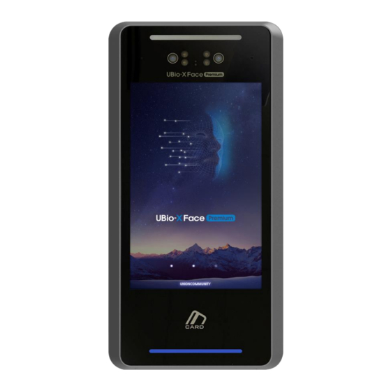
Page 3: Product Introduction
Product Introduction Front Part Name & Functions illuminance Sensor IR LED Flash LED IR Camera Microphone Camera Touch LCD Display RF Card & Mobile Card recognizes Area Speaker USB Memory Slot Fingerprint Sensor Barcode Reader Name Function Descriptions Turn on the LED Light for Face Authentication in a dark Flash LED environment. -
Page 4: Rear Part Name & Functions
Rear Part Name & Functions State Input(5pin) FUSE Wiegand(5pin) RS-485 Termination Resistor Set SW RS-232(3pin) Lock Output(7pin) Ethernet Input Power/RS-485(4pin) Lock Power Set SW Motor Lock(2pin) Warning Lamp(3pin) RS-232(3(5)pin) Thermal Image Camera(5pin) 5V Output(2pin) Fingerprint Sensor(5pin) Name Function Descriptions State Input(5pin) Connect Inside Open/ Door Lock State Input Cable Wiegand Connect the Wiegand Input / Output Cable... -
Page 5: Dimensions
Dimensions UBio-X Face Premium 23.8 143.3 289.5 UBio-X Face Premium FQR 143.3 343.2 73.6... -
Page 6: Product Specifications
Product Specifications Classification Feature Specifications 1.8GHz Quad Core Memory 16GByte eMMC + 4GByte DDR System 8inch TFT IPS Panel, 800x1280 pixel Touch Screen Capacitive Touch Biometric Face & Fingerprint Authentication ISO14443 Type A/B, Felica, ISO15693, HID15693, MiFare, 125KHz EM, HID Prox, RF Card HID ISO14443 MiFare/SEOS/DesFire(Optional) HID ISO15693 SE(Optional) -
Page 7: Cable Specifications
Cable Specifications 15V/24V Power Connection Function/Label Color Input Power/ 15V/24V Ground/GND BLACK 5V Output Power Connection Function/Label Color 5V Output/5V SKY BLUE Ground/GND BLACK Motor Connection Function/Label Color Motor+ /M+ YELLOW Motor- /M- BROWN Warning Lamp Connection Function/Label Color Green Lamp/L_G GREEN Red Lamp/L_R Ground/GND... - Page 8 Wiegand IN/OUT Connection Function/Label Color Wiegand Out 0/WO0 ORANGE Wiegand Out 1/WO1 YELLOW Wiegand In 0/WI0 BROWN Wiegand In 1/WI1 PINK Ground/GND BLACK State Input Connection Function/Label Color Door Monitor 0/DM0 YELLOW Door Monitor 1/DM1 GREEN Door Monitor 2/DM2 BLUE Inside Open/EXT ORANGE Ground/GND...
-
Page 9: Components
Components UBio-X Face Premium * The Power Input Cable is connected to the product. - Page 10 UBio-X Face Premium FQR * The Metal Bracket & Plastic auxiliary bracket are fastened to the product. * The Power Input Cable is connected to the product.
- Page 11 UBio-X FQR * A separate product configuration to add FQR functionality to the UBio-X Face Premium.
-
Page 12: Check In Advance Safety Precautions
Check in advance Safety Precautions WARNING : Failure to follow the instructions may result in death or serious injury to the user. CAUTION : Failure to follow the instructions may result in moderate injury or property damage. WARNING Installation Do not disassemble, repair or modify arbitrarily. * This may result in electric shock, fire or product damage. -
Page 13: Correct Face Enrollment And Authentication Method
Correct Face Enrollment and Authentication method Face Enrollment Method * Do not wear a hat or sunglasses that cover your face. * Register after making sure that the lower part of the forehead is not covered by hair, etc. (Criteria for taking passport photos) * Keep the distance between the product and your face about 50cm. -
Page 14: Correct Fingerprint Enrollment And Authentication Method
Correct Fingerprint Enrollment and Authentication Method Correct Fingerprint Enrolment Method * If possible, use your index finger to input as if you were handprinting. Typing with only your fingertips touching is not the right way to type. Make sure that the very center of the fingerprint touches the center of fingerprint sensor glass. -
Page 15: Installation
Installation Precautions on Installation * Be sure to install the product indoors. * Do not install in an environment with backlight or direct sunlight as this may reduce the face recognition rate. * When using a mobile card, keep a distance of at least 1m to avoid signal interference. -
Page 16: Fixing The Bracket
Fixing the Bracket * Fix the bracket firmly in the selected position using the bracket fixing screws. Fix using metal bracket * Fasten the metal bracket with 4x25(4ea) wall mounting screws. Fix using metal bracket & auxiliary bracket * Fasten the plastic auxiliary bracket with 4x25(4ea) wall mounting screws. * Fasten the metal bracket to the auxiliary bracket using 4x8(6ea) bracket mounting screws. -
Page 17: Wiring Connection
Wiring Connection Wiegand Connection Wiegand Input Connection 3/WI0 4/WI1 5/GND RF Card Reader UBio-X Face Premium VS-R20D Wiegand Output Connection 1/WO0 2/WO1 5/GND Controller... -
Page 18: Ethernet Connection
Ethernet Hub Connection * Connect to PC through Ethernet HUB using CAT-5 UTP cable. Ethernet HUB UBio-X Face Premium Direct connect to PC * With Auto-MDI/MDI-X function, it is directly connected to PC using Cross cable or straight type CAT-5 UTP cable. -
Page 19: Lock Connection
One system, one Lock connection/ Door state input & Exit button 1/L1NC 7/GND 1/DM0 4/EXIT 5/GND * SW4 On position UBio-X Face Premium Lock EB-030 Exit button Two system, one Lock Connection/ Door state input 1 L1NC System 1 7/GND... - Page 20 One system, one Lock connection/ Door state input & Exit button 3/L1NO 7/GND 1/DM0 4/EXIT 5/GND * SW4 On Position UBio-X Face Premium EB-030 Lock Exit button Two system, one Lock connection/ Door state input 3/L1NO System 1 7/GND...
-
Page 21: Automatic Door / Exit Button
One system, one Lock connection/ Exit button connection 2/L1C 3/L1NO 4/EXIT Sensor Input Line 5/GND * SW4 Off Position Automatic door UBio-X Face Premium EB-030 Exit button Two system, one Lock Connection 2/L1C System 1 3/L1NO Sensor Input Line * SW4 Off Position... - Page 22 The white wire of the motor is connected (DC24/0.3A) with the black wire 1/Motor +/Yellow 2/Motor -/Brown 1/DM0 2/DM1 4/EXIT 5/GND UBio-X Face Premium EB-030 Exit button UBio-X Face Premium Motor Lock Function Remark (Wire Color) (Wire Color) Motor +...
-
Page 23: Warning Lamp Connection
Connect the warning Lamp to indicate the status externally, such as in meal mode. * When authentication is successful, a green light is turned on, and fails, a red light is turned on. Warning Light Green * SW4/SW5 On Position 1/L_G 2/L_R UBio-X Face Premium 3/GND... -
Page 24: Lock Controller Connection Via Rs-485
Lock Controller Connection via RS-485 If you need enhanced security in preparation for an attempt to forcibly open the door due to power cut off or product destruction of UBio-X Face Premium, you can enhance security by connecting the BLC-015 Lock Controller. -
Page 25: Input Power Connection
* When wiring the DC cable, be careful not to wire it with other cables such as communication cables and AC power cables. * To prevent the cable from breaking, wire the power cable safely by using cable molding, etc. Cable specification Maximum extension length(A) AWG#18 AWG#20 AWG#22 UBio-X Face Premium 15V 4A Adapter... -
Page 26: External Relay Connection
* The external relay connection for application to turnstile Gate, etc. is as shown in the figure below. * Depending on the UBio-X Face Premium input voltage, select and apply the relay coil voltage either 12V relay or 24V relay. -
Page 27: Fcc Compliance Information
FCC Compliance Information This Device complies with part 15 of the FCC Rules. Operation is subject to the following two conditions : (1) This device may not cause harmful interference, and (2) this device must accept any interference received, including interference that may cause undesired operation.
Need help?
Do you have a question about the UBio-X Face Premium and is the answer not in the manual?
Questions and answers