
Related Manuals for FLENDER FASTEX EC210


Summary of Contents for FLENDER FASTEX EC210
- Page 1 FLENDER COUPLINGS FASTEX Compact assembly and operating instructions 3910en Edition 05/2022 FASTEX EC210 flender.com...
- Page 2 Introduction Description FLENDER COUPLINGS Application planning FASTEX EC210 Assembly Clamping elements 3910en Disassembly Disposal Compact assembly and operating instructions Services and support Technical data Edition 05/2022...
- Page 3 Note the following: WARNING Flender products may only be used for the applications described in the catalog and in the relevant technical documentation. If products and components from other manufacturers are used, these must be recommended or approved by Flender. Proper transport, storage, installation, assembly, commissioning, operation and maintenance are required to ensure that the products operate safely and without any problems.
-
Page 4: Table Of Contents
Recommended assigned fits .................. 9 Table 7-1 Geometry data, weights, tightening torques ............14 Figures Figure 2-1 Construction of the clamping element FASTEX EC210 ......... 7 Figure 4-1 Fit assignment ......................9 Figure 7-1 Parts overview FASTEX EC210 ................13... -
Page 5: Introduction
Only the knowledge of these instructions can avoid faults on the clamping element and ensure fault-free and safe operation. Non-adherence to the instructions can cause product or property damage or personal injury. Flender does not accept any liability for damage or operating failures that are due to non-adherence to these instructions. -
Page 6: Intended Use
Table 7-1 is not exceeded at any operating point. The identification and information on the conditions of use can be found in the main operating instructions of the assembly supplier. FASTEX EC210 Clamping element 3910de Compact assembly and operating instructions 05/2022... -
Page 7: Description
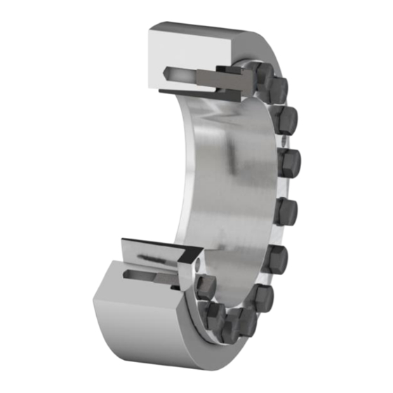
Contact surfaces 1 2 3 4 5 Shaft and hub/hollow shaft Inner ring Outer ring Hexagon head screws Shaft Hollow shaft/hub Figure 2-1 Construction of the clamping element FASTEX EC210 FASTEX EC210 Clamping element 3910de Compact assembly and operating instructions 05/2022... -
Page 8: Application Planning
3.1 Storage of the clamping element The clamping element, unless not specifically ordered otherwise, is supplied with preservation and can be stored for up to 12 months in a dry and dust-free storage room. FASTEX EC210 Clamping element 3910de Compact assembly and operating instructions 05/2022... -
Page 9: Assembly
(DS ≤ 160 mm), Ra ≤ 3,2 µm Shaft tolerance g6 (DS > 160 mm Ra ≤ 3,2 µm Bore tolerance Figure 4-1 Fit assignment FASTEX EC210 Clamping element 3910de Compact assembly and operating instructions 05/2022... -
Page 10: Assembling The Clamping Element
5. Tighten the hexagon head screws (3) one after the other in several turns until the inner ring (1) is aligned with the outer ring (2). The prescribed tightening torque can be found in the section Tightening torques and wrench sizes. FASTEX EC210 Clamping element 3910de Compact assembly and operating instructions 05/2022... -
Page 11: Disassembly
4. Remove the clamping set from the hollow shaft/hub (5). Use suitable lifting devices for this purpose. When reinstalling the clamping element please observe the information in the chapter Assembly (Page 10). FASTEX EC210 Clamping element 3910de Compact assembly and operating instructions 05/2022... -
Page 12: Disposal
Flender GmbH Schlavenhorst 100 46395 Bocholt Deutschland Tel.: +49 (0)2871/92-0 Fax.: +49 (0)2871/92-2596 Flender GmbH (http://www.flender.com) FASTEX EC210 Clamping element 3910de Compact assembly and operating instructions 05/2022... -
Page 13: A Technical Data
Technical data Geometry data and tightening torques In this section you can find dimension drawings and technical data for the Flender clamping elements.: 1 2 3 Inner ring Outer ring Hexagon head screws Shaft Hollow shaft/hub Figure 7-1 Parts overview FASTEX EC210... -
Page 14: Table 7-1 Geometry Data, Weights, Tightening Torques
75 114 44,5 7900 70 124 50 43,5 6200 95 x 170 75 124 50 43,5 7400 80 124 50 43,5 8600 70 124 50 43,5 6200 100 x 170 75 124 50 43,5 7400 80 124 50 43,5 8600 flender.com... - Page 15 77,5 82000 36,3 200 x 340 160 238 98 77,5 91000 36,3 165 238 98 77,5 102000 36,3 160 268 120 107,5 96,5 105000 220 x 370 170 268 120 107,5 96,5 122000 180 268 120 107,5 96,5 138000 flender.com...
- Page 16 400 538 242 1150000 1250 380 552 247 1557000 1650 480 x 770 390 552 247 1648000 1650 410 552 247 1818000 1650 400 572 241 1653000 1650 500 x 820 410 572 241 1725000 1650 430 572 241 1915000 1650 flender.com...
- Page 17 FASTEX EC210 Compact assembly and operating instructions 3910de Edition 05/2022 Flender GmbH Alfred-Flender-Straße 77 46395 Bocholt Germany flender.com...
Need help?
Do you have a question about the FASTEX EC210 and is the answer not in the manual?
Questions and answers