
Related Manuals for FLENDER FASTEX IN220


Summary of Contents for FLENDER FASTEX IN220
- Page 1 FLENDER COUPLINGS FASTEX Compact assembly and operating instructions 3909en Edition 05/2022 FASTEX IN220...
- Page 2 Introduction Description FLENDER COUPLINGS Application planning FASTEX IN220 Assembly Clamping elements 3909en Disassembly Disposal Compact assembly and operating instructions Services and support Technical data Edition 05/2022...
- Page 3 Note the following: WARNING Flender products may only be used for the applications described in the catalog and in the relevant technical documentation. If products and components from other manufacturers are used, these must be recommended or approved by Flender. Proper transport, storage, installation, assembly, commissioning, operation and maintenance are required to ensure that the products operate safely and without any problems.
-
Page 4: Table Of Contents
Auxiliary screw assignment ..................11 Table 7-1 Geometry data, weights, tightening torques ............14 Figures Figure 2-1 Construction of the clamping element FASTEX IN220 .......... 7 Figure 4-1 Fit assignment ......................9 Figure 7-1 Parts overview FASTEX IN220 ................13... -
Page 5: Introduction
Only the knowledge of these instructions can avoid faults on the clamping element and ensure fault-free and safe operation. Non-adherence to the instructions can cause product or property damage or personal injury. Flender does not accept any liability for damage or operating failures that are due to non-adherence to these instructions. -
Page 6: Intended Use
Table 7-1 is not exceeded at any operating point. The identification and information on the conditions of use can be found in the main operating instructions of the assembly supplier. FASTEX IN220 Clamping element 3909de Compact assembly and operating instructions 05/2022... -
Page 7: Description
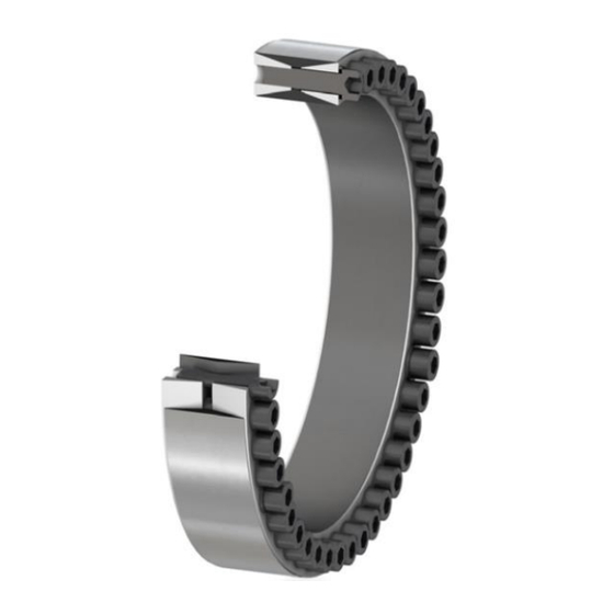
(Page 13). Contact surfaces 1 2 3 4 5 Rear cone ring Inner ring Outer ring Front cone ring Cylinder-head screw Figure 2-1 Construction of the clamping element FASTEX IN220 FASTEX IN220 Clamping element 3909de Compact assembly and operating instructions 05/2022... -
Page 8: Application Planning
3.1 Storage of the clamping element The clamping element, unless not specifically ordered otherwise, is supplied with preservation and can be stored for up to 12 months in a dry and dust-free storage room. FASTEX IN220 Clamping element 3909de Compact assembly and operating instructions 05/2022... -
Page 9: Assembly
Recommended assigned fits component tolerance surface quality k11 – h11 Ra ≤ 3,2 µm Shaft tolerance N11 – H11 Ra ≤ 3,2 µm Bore tolerance Figure 4-1 Fit assignment FASTEX IN220 Clamping element 3909de Compact assembly and operating instructions 05/2022... -
Page 10: Assembling The Clamping Element
4. The shaft must fill the entire length of the inner ring (2). 5. Tighten the cylinder-head screws (3) crosswise in several turns. The specified tightening torque can be found in the Tightening torques and widths A/F section. FASTEX IN220 Clamping element 3909de Compact assembly and operating instructions 05/2022... -
Page 11: Disassembly
5. Check the hub bore and the shaft for damage and protect them against corrosion. When reinstalling the clamping element please observe the information in the chapter Assembly (Page 10). Table 5-1 Auxiliary screw assignment FASTEX IN220 Clamping element 3909de Compact assembly and operating instructions 05/2022... -
Page 12: Disposal
Flender GmbH Schlavenhorst 100 46395 Bocholt Deutschland Tel.: +49 (0)2871/92-0 Fax.: +49 (0)2871/92-2596 Flender GmbH (http://www.flender.com) FASTEX IN220 Clamping element 3909de Compact assembly and operating instructions 05/2022... -
Page 13: A Technical Data
Technical data Geometry data and tightening torques In this section you can find dimension drawings and technical data for the Flender clamping elements.: 1 2 3 4 5 Rear cone ring Inner ring Outer ring Front cone ring Cylinder-head screw... -
Page 14: Table 7-1 Geometry Data, Weights, Tightening Torques
180 x 235 46600 6,00 190 x 250 57300 8,00 200 x 260 71000 8,20 220 x 285 93200 11,00 240 x 305 117300 12,20 260 x 325 144000 13,20 280 x 355 177700 19,20 300 x 375 214100 20,50 flender.com... - Page 15 647600 1130 64,60 460 x 565 130 102 96 677000 1130 67,40 480 x 585 130 102 96 741800 1130 71,00 500 x 605 130 102 96 809500 1130 72,60 520 x 630 130 102 96 861000 1130 80,00 flender.com...
- Page 16 FASTEX IN220 Compact assembly and operating instructions 3909de Edition 05/2022 Flender GmbH Alfred-Flender-Straße 77 46395 Bocholt Germany flender.com...
Need help?
Do you have a question about the FASTEX IN220 and is the answer not in the manual?
Questions and answers