Herz clever&smart Control Box Clima Instruction Manual
Hide thumbs
Also See for clever&smart Control Box Clima:
- Installation and operating instruction (46 pages)
Table of Contents
Advertisement
Quick Links
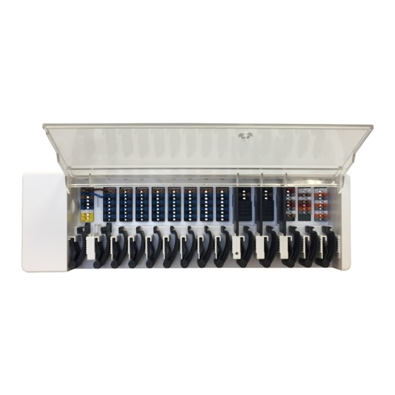
HERZ clever&smart Control Box Clima
Description
The HERZ clever&smart Control Box Clima is a universal heating and zoning controller for Surface heating and cooling
systems. In conjunction with HERZ clever&smart Room Controller, HERZ clever&smart Room Sensor or HERZ
clever&smart LEDcontroller, this enables efficient use and function control of your surface heating and surface cooling
with intuitive operability. The inputs and outputs can be freely assigned via HERZ clever&smart Room Controller Clima,
so that different heating and cooling systems can be implemented.
Important characteristics of the HERZ clever&smart Control Box Clima:
Control of 8 heating and cooling zones with 1 - 4 thermoelectric actuators each
l
Detection of room temperature and humidity in conjunction with HERZ clever&smart Room Controller,
l
HERZ clever&smart LEDcontroller or HERZ clever&smart Room Sensor
Optional: Weather compensated via an external temperature sensor
l
Optional: Dew point dependent via room humidity measurement
l
Optional: Control heating circuit pump and mixer (PWM oder 0-10V) possible
l
2 separate CAN bus interfaces for building network and private floor or apartment network
l
Connectable with other HERZ products via CAN bus
l
Control of mixers, valves and energy generators via 0-10V / PWM
l
2 additional floating changeover contacts (terminals J and K) for flexible assignment with additional functions
l
Innovative strain relief and coloured terminal strip
l
Up to 20 1-Wire temperature sensors can be connected (incl. a maximum of 8 LEDcontroller)
l
Safety Instructions
General
By no means does the controller replace the safety appliances on site!
l
Temperature values which are set too high can lead to scalding or damage to the system. Scalding protection must
l
be provided by the customer!
The temperature sensor cables must be routed separately from mains voltage cables, and must not, for example,
l
be routed in the same cable duct!
Wall Installation
Install the controller only in dry areas and under the ambient conditions described in "Specifications".
l
Low-voltage cables such as temperature sensor cables must be routed separately from mains voltage cables. Feed
l
temperature sensor cables only into the left-hand side of the unit, and mains voltage cables only into the right-hand
side.
Wall Installation
Fix the DIN rail horizontally to the wall using screws.
Installation
1. Place the Control Box on the upper edge of the DIN rail with the
locking catch on top. 2. Engage the unit by pressing it down. Ensure
that the locking catches engage completely and that the unit is firmly
seated on the rail.
Disassembly
Remove the Control Box from the DIN rail by inserting two
screwdrivers into the eyelets and pulling them down-wards.
Separation walls and cover
The separation walls and the cover can be removed for easier
connection of the cables. They must then be reinstalled in order to
safely separate areas carrying mains voltage from areas carrying
low voltages.
Open the cover (90 ° degree) and then pull it out of the attachment
laterally.
If the terminal blocks (B-I) are to be supplied with a voltage other than the mains voltage,
proceed as follows:
1.
Remove existing bridges A1 - B1 and A2 - B2
2.
It is absolutely necessary to insert a separating wall between A - B.
3.
Connect the power supply to B1 (L) and B2 (N).
4.
Observe max. switching power of relay and fuse (4 AT)
Heating zones with 230 VAC actuators
Heating zones with e.g. 24 VAC actuators (separation wall)
(bridge)
HERZ clever&smart Control Box Clima
Technical Data
HERZ clever&smart
Model
Individual room control system for surface heating and cooling
Control Box Clima
Electrical specifications
Power supply
230 VAC (+/- 5 %), 50-60 Hz
Power consumption / standby
0,5 - 2,5 W/ 0,5 W
(Pos. A, left) 2 A slow blow 250 V Fuse protection for terminal
Internal fuse 1
1
area A and electronics
(Pos. B, right) 4 A slow blow 250 V Fuse protection for terminal
Internal fuse 2
1
area B - I
Protection Class
IP 20
Protection class / overvoltage category
II / II
Inputs / Outputs
Inputs
Quantity
Measuring range / design
< 20 pieces (incl.
1-Wire temperature sensor powered
- 55 °C ... 125 °C (3 pole version)
max. 8
LEDcontroller)
PWM inputs
2 (N2, N5)
Outputs
Switching relay outputs
11
Relay heat pump
1
230 VAC, 4 A, (AC1 920 VA, AC3 185W)
Relay actuator
8
230 VAC, 4 A, (AC1 920 VA, AC3 185W)
Relay additional function
2
Potential-free max. 4 A
PWM output
3 (N1, N4, N8)
for 10 kΩ working resistance 1 kHz, level 10 V
of which 0-10 V / PWM switchable
2 (N1, N4)
total max. 12 W for external devices e.g. HERZ clever&smart
+ Voltage output 24 VDC
3
Room Controller or mixer motor
Max. cable length
Up to 50 m parasitic, up to 100 m powered,
1-Wire Sensors
Use twisted pair cable (LIYCY 2 x 2 x 0.75 mm²)
Especially when using HERZ clever&smart LEDcontroller,
ensure sufficient conductor cross-section to avoid impermissible
voltage drop.
< 3 m; for ≥ 3 m, use a shielded twisted pair cable (2 x 2 x 0.22
CAN
mm²) . Connect the shielding to the protective conductor on one
side. Max. cable length of the complete system 200 m.
0-10 V / PWM
< 3 m
24 VDC
< 30 m
mechanical relay
< 30 m
Interface
Field bus
2x
CAN bus, separate building CAN bus and private CAN bus
Permissible Ambient Conditions
for controller operation
0 °C - 40 °C, max. 85 % rel. humidity at 25 °C
for transport / storage
0 °C - 60 °C, no moisture condensation permitted
Other Specifications and Dimensions
Housing design
multi-part ABS
Installation methods
DIN rail mounting or wall mounting on DIN rail
Overall dimensions
95 mm x 303 mm x 57 mm
Light diode
14 x LED green
Real Time Clock
RTC with 24 hour power reserve
Operation
via HERZ clever&smart Room Controller
LED status
LED A
Lights up if mains voltage is present and relay A is switched.
LED B - K
Lights up if relays B - K are switched
Lights up if the private CAN bus is active.
LED L
Flashes at 1 Hz (60 x / minute) if there is an error in the private CAN bus.
Lights up if the building CAN bus and the 1-wire bus are active.
Flashes at 1 Hz (60 x / minute) if there is an error in the building CAN.
LED M
Flashes at 3 Hz (180 x / minute) if there is an error in the 1-Wire connection. EXCEPTION: If the building CAN
bus remains unused, a flashing of the LED M is normal and does NOT mean that there is a error.
LED N
Lights up if outputs V1, V2 or V3 are active.
System structure
Herz Armaturen Ges.m.b.H. | Richard-Strauss-Straße 22 | 1230 Vienna, Austria | +43 (0) 1 616 26 31 - 0 | office@herz.eu |
www.herz-armaturen.at | 3F81012-EN-08/2023
Instruction Manual
HERZ clever&smart Control Box Clima
3 F810 12
Scope of delivery
Detailed instruction
HERZ clever&smart Control Box Clima
l
2 spare fuses, 1 x 2 AT, 1 x 4 AT
l
Additional separation wall
l
DIN rail H= 35 mm L= 280 mm
l
2 screws 3.5 x 35 mm and 2 dowels S6
l
HERZ clever&smart Control Box Clima instruction manual
l
SCAN ME
> www.herz-armaturen.at/solutions/clever-and-smart/manuals
General notes
This manual contains basic instructions and important information about safety, installation and operation. Before
commissioning and operation, the installer / specialist and the operator of the system have to read the manual
completely. It is an automatic electric temperature controller for household and similar applications. In addition,
observe the accident prevention regulations applicable in the respective countries, the applicable standards and
regulations and the installation and operating instructions for additional system components. Installation, electrical
connection, commissioning and maintenance may only be carried out by specialists who possess the appropriate
training. Users: Make sure that the specialist gives you detailed information on the function and operation of the
controller.
Advertisement
Table of Contents

Related Manuals for Herz clever&smart Control Box Clima


Summary of Contents for Herz clever&smart Control Box Clima
- Page 1 Users: Make sure that the specialist gives you detailed information on the function and operation of the controller. Herz Armaturen Ges.m.b.H. | Richard-Strauss-Straße 22 | 1230 Vienna, Austria | +43 (0) 1 616 26 31 - 0 | office@herz.eu | www.herz-armaturen.at | 3F81012-EN-08/2023...
Need help?
Do you have a question about the clever&smart Control Box Clima and is the answer not in the manual?
Questions and answers