
Related Manuals for Herz clever&smart Control Box Heating


Summary of Contents for Herz clever&smart Control Box Heating
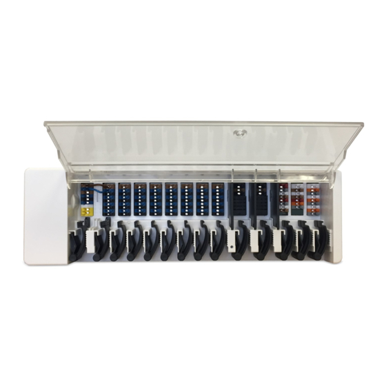
- Page 1 HERZ clever&smart Control Box Heating Heating circuit controller for surface heating systems 3 F810 11 Installation and operating instruction Read carefully before installation, commissioning and operation...
-
Page 2: Table Of Contents
Set Operation Hours Expert Menu Settings Devices Rooms Temperature Functions Control Box Zones Example zone setting WiFi Access Point WiFi Sensor Integrating devices without WiFi Service Values Connecting HERZ clever&smart App to the HERZ clever&smart Room Controller WiFi Tips Support... -
Page 3: Safety Instructions
HERZ clever&smart Control Box Heating Safety Instructions EU-Conformity By affixing the CE mark to the unit the manufacturer declares that the HERZ clever&smart Control Box Heating conforms to the following relevant safety regulations EU low voltage directive 2014/35/EU EU electromagnetic compatibility directive 2014/30/EU EU RoHS Directive 2011/65/EU EU WEEE Directive 2012/19/EU (Reg.nr. -
Page 4: Changes To The Unit
Description HERZ clever&smart Control Box Heating Description The HERZ clever&smart Control Box Heating is a universal heating and individual room controller for surface heating systems. In combination with HERZ clever&smart Room Controller, HERZ clever&smart Room Sensor or HERZ clever&smart LEDcontroller, this enables efficient use and function control of your surface heating with intuitive operation. -
Page 5: Technical Data
0-10 V / PWM 2 (N1, N4) switchable + Voltage outputs 24VDC Total max. 12 W for external devices e.g. HERZ clever&smart Room Controller or mixer motor Interface Fieldbus CAN bus (separate building CAN bus and private CAN bus) Max. -
Page 6: Scope Of Supply
Fix the DIN rail horizontally to the wall using screws. Installation 1. Place the HERZ clever&smart Control Box Heating on the upper edge of the DIN rail with the locking catch on top. 2 Engage the device by pressing it down. Ensure that the locking catches engage completely and that the device is firmly seated on the rail. -
Page 7: Electrical Connection
HERZ clever&smart Control Box Heating Electrical Connection Low-voltage cables, such as temperature sensor cables, must be laid separately from mains voltage cables. Before working on the unit, switch off the power supply and secure it against being switched on again! Check that there is no power flowing! Electrical connections may only be made by a specialist and in compliance with the applicable regulations. -
Page 8: Electrical Terminals
Example Wiring of Terminal Blocks Mains connection heating circuit pump Actuators for the heating zones HERZ clever&smart Room Controller in the private CAN bus Potential-free switching contacts for additional functions Private CAN bus For linking devices within a housing unit, such as a single-family house or a flat. -
Page 9: Led Status
HERZ clever&smart Control Box Heating 0-10 V /PWM outputs for additional functions Building CAN bus and 1-Wire sensors Building CAN bus For linking devices across several units, such as flats, offices or hotel rooms. Only shares information relevant for optimising the... -
Page 10: Wiring Structures
HERZ clever&smart Control Box Heating Wiring structures CAN bus Description Implementation Admissibility Line Yes, optimal installation with maximum range. Tree Star 1-Wire-Bus Description Implementation Admissibility Line Yes, optimal installation with maximum range. Tree Possible without guarantee for small systems with short line lengths and few network participants. -
Page 11: Connection Examples Herz Clever&Smart Room Controller
HERZ clever&smart Control Box Heating Connection examples HERZ clever&smart Room Controller Do not combine devices designed for heating only (HERZ clever&smart Room Controller/HERZ clever&smart Control Box Heating) with devices designed for heating and cooling (HERZ clever&smart Room Controller Clima/HERZ clever&smart Control Box Clima). -
Page 12: Connection Example Single-Family House With >8 Zones
Example: Line structure with several HERZ clever&smart Control Box Heating via the private CAN bus (e.g. within a residential unit). A 120 Ohm terminating resistor must be set between the CAN Low and CAN High connections on the first and last device in... -
Page 13: Connection Example Apartment Building
Connection example apartment building Example: Line structure with several HERZ clever&smart Control Box Heating via the building CAN bus (e.g. across several residential or commercial units). Use building CAN bus on terminal block M so that no private data such as room temperatures or holiday mode are shared across flats. -
Page 14: Connection Examples 1-Wire Sensors
When connecting the 1-Wire sensors, please record the 16-digit 1-Wire ID and the location of the sensor for later commissioning of the system! The 1-Wire ID can be found in the device housing and in the device menu under: Devices -> HERZ clever&smart Control Box Heating -> Resources -> 1-Wire Sensor. Example 1: Line. -
Page 15: Connection Example Herz Clever&Smart Ledcontroller
HERZ clever&smart Control Box Heating Connection example HERZ clever&smart LEDcontroller Example line: The installation leads from one sensor to the next. A twisted pair cable must be used for the connecting cable. The 1-Wire system must be realised with 3 wires (5 VDC, DQ, GND). The total cable length can thus be up to 100 m. Use a suitable twisted pair cable and ensure sufficient conductor cross-section, e.g. -
Page 16: 1-Wire Id Overview
2. By assigning the HERZ clever&smart Room Sensor via the 1-wire ID (16-digit hexadecimal number) If this method is selected, it is helpful to note the 1-wire ID of the HERZ clever&smart Room Sensors in connection with the room in which the respective sensor was installed for later assignment within the scope of the system configuration. -
Page 17: Setup Wizard
Setup Wizard The setup wizard in the HERZ clever&smart Room Controller starts automatically when the device is commissioned for the first time and guides you through the necessary basic settings in the correct sequence. Press the arrow keys in the upper right/left corner to return to the next or previous setting. -
Page 18: Operation
To parameterise the HERZ clever&smart Control Box Heating, you need at least one HERZ clever&smart Room Controller. This is connected to the HERZ clever&smart Control Box Heating via the private CAN bus as described above (see "Electrical Connection" on page 7). -
Page 19: Operating Mode
HERZ clever&smart Control Box Heating Operating Mode Overview > Operating Mode Back/ Forward Menu Navigation back to overview Navigation to the main menu Room Operating Modes Display of the selected room The operating mode shown in colour is currently active and can be changed by selecting another mode. -
Page 20: Set Operation Hours
HERZ clever&smart Control Box Heating Set Operation Hours Overview > Operating Mode > Menu > Timer Setting of individual heating and cooling times for the selected room. Menu Opens the copy function. This function allows you to copy the heating times for... -
Page 21: Expert Menu
HERZ clever&smart Control Box Heating Expert Menu Overview > Operating Mode > Menu > Expert Select Language Date & Time Set the device language Setting the time and date and automatic summertime/wintertime changeover Settings Parameterisation of the heating Service Values... -
Page 22: Settings
HERZ Add, manage and remove rooms and clever&smart Control Box Heating. This assign them to connected devices menu is only visible if this HERZ Zones clever&smart Room Controller was set as the "Configurator" ("Expert > Assigning rooms to heating zones Settings >... -
Page 23: Devices
Overview > Operating mode > Menu > Expert > Settings > Devices Do not combine devices designed for heating only (HERZ clever&smart Room Controller/HERZ clever&smart Control Box Heating) with devices designed for heating and cooling (HERZ clever&smart Room Controller Clima/HERZ clever&smart Control Box Clima). -
Page 24: Rooms
HERZ clever&smart Control Box Heating Rooms Overview > Operating mode > Menu > Expert > Settings > Rooms Add Room Adding rooms Room 2 Setting of location, sensors of the respective room Overview > Operating mode > Menu > Expert > Settings > Room 2... -
Page 25: Temperature
Icon + serial number Already selected sensor When using 1-Wire sensors, these are displayed via the CAN ID of the HERZ clever&smart Control Box Heating + a resource number. With 1-Wire sensors, the temperature and the 1-Wire ID are displayed alternately. -
Page 26: Functions Control Box
HERZ clever&smart Control Box Heating Functions Control Box Overview > Operating mode > Menu > Expert > Settings > Control Box Activate and set additional functions on free outputs of the HERZ clever&smart Control Box Heating. Further functions on the next page. - Page 27 HERZ clever&smart Control Box Heating Overview > Operating mode > Menu > Expert > Settings > Control Box > Thermostat 2 Switches the defined output to the set room / rooms depending on time and temperature. Output Assign the output to be switched by the function.
- Page 28 HERZ clever&smart Control Box Heating Overview > Operating mode > Menu > Expert > Settings > Control Box > HC mixer The heating circuit mixer function controls the flow temperature via a 0-10 V / PWM mixer depending on the outdoor temperature.
- Page 29 Outdoor sensor By default, the output at terminal Assignment of the outdoor sensor for block A of the HERZ clever&smart weather-compensated control of the Control Box is defined here. heating circuit. Follow-up time Curve...
- Page 30 HERZ clever&smart Control Box Heating Overview > Operating mode > Menu > Expert > Settings > Control Box > Difference The difference function switches the defined output as soon as there is a preset temperature difference between the source and target sensor.
- Page 31 Overview > Operating mode > Menu > Expert > Settings > Control Box > Energy request The function energy request switches the defined output when the rooms require energy depending on the set delay. Output Selection of the output on the HERZ clever&smart Control Box Heating that is switched when a zone requires Delay energy.
-
Page 32: Zones
HERZ clever&smart Control Box Heating Zones verview > Operating mode > Menu > Expert > Settings > Zones Zones Selection of zones to be set or managed. Overview > Operating Mode > Main Menu > Expert > Settings > Zones > Zone B... -
Page 33: Example Zone Setting
HERZ clever&smart Control Box Heating Example zone setting Step 1 Select the respective zone. Step 2 Select the room corresponding to the zone. Step 3 Step 4 Set the desired outdoor switch- Set the desired outdoor switch- off temperature for the Normal off temperature for Eco (S/W (S/W Day) mode. -
Page 34: Wifi
HERZ clever&smart Control Box Heating WiFi Overview > Operating mode > Menu > Expert > Settings > WiFI This menu is only available when a HERZ clever&smart Room Controller WiFi is connected. WiFi status Activate WiFi Information about the WiFi status and... - Page 35 HERZ clever&smart Control Box Heating Connecting the HERZ clever&smart DNS/ DNS 2 Control Box Heating to a WPS- enabled router Entering the DNS address WiFi Sensor Access Point Settings for the LED display and the transmission interval Settings for routing and the WPS...
-
Page 36: Access Point
WLAN router. If there is no router, communication takes place via the access point of the HERZ clever& smart room controller. WiFi Sensor Overview > Operating Mode > Menu > Expert > Settings > WiFi > WiFi Sensor... -
Page 37: Integrating Devices Without Wifi
HERZ clever&smart Control Box Heating Integrating devices without WiFi If no WLAN is available, devices can be added to the network via the menu 'Expert -> Settings -> Devices - > Add device'. -
Page 38: Service Values
"Manage Access" Log in to app with e-mail and password If your HERZ clever&smart Room Controller WiFi is located in the same WiFi network as your mobile device, you can activate it by clicking the "Done! Search HERZ clever&smart Room Controller on WiFi to connect to each other. -
Page 39: Tips
Control Box Heating in the network to the latest version. HERZ clever&smart Control Box Heating: clever&smart Room Controller Menu > Expert > Settings > Devices > HERZ clever&smart Control Box Heating > Firmware HERZ WiFi) clever&smart Room Controller: Menu > Expert > Service values > System update, start update on see "Devices"... - Page 40 Final Declaration Although these instructions have been created with the greatest possible care, the possibility of incorrect or incomplete information cannot be excluded. Subject as a basic principle to errors and technical changes. Herz Armaturen Ges.m.b.H. Richard-Strauss-Straße 22 1230 Vienna, Austria +43 (0) 1 616 26 31 - 0 office@herz.eu...
Need help?
Do you have a question about the clever&smart Control Box Heating and is the answer not in the manual?
Questions and answers