Table of Contents
Troubleshooting

Related Manuals for Haier GE Vertical Zoneline AZ90E09D C


Summary of Contents for Haier GE Vertical Zoneline AZ90E09D C
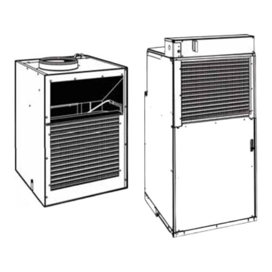
- Page 1 Technical Service Guide June 2017 Vertical Zoneline AZ90E09D_C AZ91H09D_C AZ90E12D_C AZ91H12D_C AZ90E18D_C AZ91H18D_C AZ91H09E_C AZ91H12E_C AZ91H18E_C Rear View AZ91H18E_S 9K, 12K, 18K Small Large Chassis Chassis 31-9269...
-
Page 2: Safety Information
Safety Information IMPORTANT SAFETY NOTICE The information in this service guide is intended for use by individuals possessing adequate backgrounds of electrical, electronic, and mechanical experience. Any attempt to repair a major appliance may result in personal injury and property damage. -
Page 3: Table Of Contents
Table of Contents Safety Information ........................2 Table of Contents ..........................3 Safety Requirements ........................5 Nomenclature ..........................6 Introduction ...........................7 Changes to Design ........................7 Features ............................8 Electronic Control Sequence Of Operation ..................9 Low Voltage Interface Connections ..................11 Remote Wall Thermostat ......................11 Connecting a Remote Wall Thermostat ................12 Desk Control .........................13 Auxiliary Fan Control ......................13 Service ..........................13... - Page 4 Right Side Components ......................26 Fault Codes and Alarm Status ......................27 ..............29 Main Board Front ........................30 Components Testing ........................31 Refrigeration Sequence of Operation ...................34 Sealed Refrigeration System Repairs ..................36 Regrigerant Charging ......................36 Method of Charging / Repairs ....................36 Undercharged Refrigerant Systems ..................37 Overcharged Refrigerant Systems ..................37 Restricted Regrigerant System .....................38 Hermetic Components Check ......................39...
-
Page 5: Safety Requirements
Safety Requirements GE Factory Service Employees are required to use safety glasses with side shields, safety gloves and steel toe shoes for all repairs. Electrically Rated Glove and Steel Toed Work Boot Dyneema®Cut Resistant Dyneema® Cut Resistant Glove Glove Keeper Cut Resistant Sleeve(s) Plano Type Safety Glasses Prescription Safety Glasses... -
Page 6: Nomenclature
Nomenclature Model Number A Z 9 1 H 1 2 D 2 C W 1 Engineering Revision Zoneline® K: GMCC Compressor W: Rechi Compressor Chassis Series 90: Cooling w/ Electric Resistance Heat C: Corrosion 91: Cooling w/ Heat Pump and Electric S: Small Resistance Heat Heater Wattage... -
Page 7: Introduction
Introduction This service guide is designed to be used in conjunction with the installation manuals provided with each GE Vertical Zoneline. This service guide was written to assist the professional HVAC service technician to quickly and accurately diagnose and repair any malfunctions of this product. This guide, therefore, will deal with all subjects in a general nature (i.e.: All text will pertain to all models). -
Page 8: Features
Features • Quiet Start/Stop Fan Delay: The fan start and stop delays prevent abrupt changes in room acoustics due to the compressor energizing or stopping immediately. Upon call for cooling or allows for "free cooling" by utilizing the already cool indoor coil to its maximum capacity by running for 30 seconds after the compressor shuts off. -
Page 9: Electronic Control Sequence Of Operation
Electronic Control Sequence Of Operation NOTE: The GE Vertical Zoneline is operated by a wired remote wall thermostat which is connected to an electronic control board at the GE Vertical Zoneline. Compressor and Reversing Valve Control Active Mode Compressor Reversing Valve State* Cooling De-Energized Heat - Heat Pump (Compressor... - Page 10 Compressor Lock Out Time The lockout feature ensures that the compressor is de-energized for a period of time. The timer varies randomly from 180 to 240 seconds. The compressor lockout is initiated every time the compressor is "off" due to: 1.
-
Page 11: Low Voltage Interface Connections
Low Voltage Interface Connections Remote Wall Thermostat All GE Vertical Zonelines have a low voltage interface connector through which a Remote Wall be controlled by using a single stage heat/cool Thermostat, Desk Control and Auxiliary Fan's remote wired wall mounted thermostat. Relay can be connected. -
Page 12: Connecting A Remote Wall Thermostat
Remote Wall Thermostat Location Connecting a Remote Wall Thermostat The thermostat should not be mounted where Caution it may be affected by drafts, discharge air from registers (hot or cold), or heat radiated from the It is the installer's sun appliances, windows, etc. The thermostat responsibility to ensure that all control wiring an area of average temperature, with good air... -
Page 13: Desk Control
Desk Control Service The GE Vertical Zonelines electronic control has Servicing / Chassis Quick Change Outs built-in provisions for connection to an external The chassis is designed for quick disconnected switch to control power to the GE Vertical and change out. For minor electrical service, Zoneline. -
Page 14: Installation
Installation Utility Closet Connection Locations IMPORTANT: Plan and locate plenum, electrical connection, drains and thermostat carefully to avoid Small Chassis Flex duct may be used for transitions only Use rigid duct for Reference Dimensions 90° bends and tees A Thermostat cable Outside wall B Incoming Power Conduit D Unit height: 30-5/8”... -
Page 15: Small Chassis
Small Chassis • Power Input: All models are hard wired to the AC power supply. A quick disconnect is provided to remove power from the GE Vertical Zoneline. CAUTION: Voltage is still applied to the input side Fuses are in line with supply on 265 volt models. - Page 16 Nameplate 10' Duct Collar Heater Diagnostic Touch Pad Pullout Disconnect Condenser Fresh Air Vent Evaporator Coil Condenser Coil Thermistors Compressor Evaporator Coil Thermistor Evaporator Coil Front Side Left and Front Sides Condenser Air Intake Heater Blower Wheel Fresh Air Vent Door Condenser Blower/Fan...
- Page 17 Fuse Block Heater Relay Pull Out Service Module Disconnect Main Control Transformer Capacitor Evaporating Coil 265 Model Front Line Fuses Pull Out Heater Relay Disconnect Transformer Transformer Fuse 265 Model Transformer Fuse – 17 –...
-
Page 18: Small Chassis Component Access
Small Chassis Component Access Control Panel Access Remove quick disconnect and nine 1/4 in. hex head screws, then slide the panel up and out of the GE Vertical Zoneline. Control Area Control Area Opened – 18 –... -
Page 19: Transformer (265 Volt Models)
Small Chassis Component Access (continued) Transformer (265 Volt Models) Transformer (265 Volt Models): Remove the control panel. One 1/2 in. nut secures the transformer to the control area bracket. Motor Winding Resistance Model Measurement Indoor Motor Outdoor Motor AZ90E09, AZ90E12, WHITE TO BROWN 48 ±... - Page 20 Small Chassis Component Access (continued) Heater Top Heater Side Side panel removed to access heater if duct cannot be removed. – 20 –...
-
Page 21: Large Chassis
Large Chassis • Power Input: All models are hard wired to the AC power supply. A quick disconnect is provided to remove power from the GE Vertical Zoneline. CAUTION: Voltage is still applied to the input side Fuses are in line with supply on 265 volt models. - Page 22 10" Duct Collar Blower Wheel Electric Control Panel Air Discharge Return Air Filter Air Intake Nameplate Fresh Air Door Lever Service Module Pull Out Compressor Disconnect Relay Front Side Blower Wheel Compartment Condenser Air Intake Evaporator Coil Thermistor Evaporator Coil Heater Capillary Tube Compressor...
-
Page 23: Large Chassis Control Panel
Large Chassis Control Panel 230 Volt Control Area Main Board L2 Compressor Fuse Indoor Air Thermistor Power Disconnect Service Display Board Compressor Relay 265 Volt Control Area Compressor Heater Indoor Air Thermistor Main Board Relay Auto Transformer Relay Power Line Service Display Board Disconnect L2 Compressor Fuse... -
Page 24: Large Chassis Component Access
Large Chassis Component Access Heater and Bracket Indoor Blower Assembly The output duct and the top panel must be removed to access the heater assembly. Two screws secure the bracket with the thermal cut-outs on it. A rear brace has two screws and must be rotated to remove. Bracket screws Brace Heater Resistance... -
Page 25: Indoor Motor And Blower Assembly
Large Chassis Component Access (continued) Indoor Motor and Blower Assembly The blower wheel is attached to the motor shaft with a 5/16 in. square head bolt. The motor is secured to the blower housing with three 3/8 in. screws. The blower wheel can be removed by separating the housing from the mount. Outdoor Motor and Blade Assembly The motor bracket is secured to the base with four 5/16 in. -
Page 26: Outdoor Shroud Assembly
Large Chassis Component Access (continued) Outdoor Shroud Assembly For easier access to the outdoor fan shroud. Cut the wire ties on the condensate drain tube to access the shroud screws. Remove the braces and bracket screws. Ensure that new wire ties are installed on the drain tube. -
Page 27: Fault Codes And Alarm Status
Fault Codes and Alarm Status Service Module The display shown below has four digits. The left two digits indicate the fault code # (1 to 24). The ON/OFF icons above these two digits indicate the current state of the fault code. The right two digits show the history count (up to 99) of the associated fault code. - Page 28 Fault Problem Action Code Front panel button stuck for Continue to monitor for "OPEN" (Unstuck) switch. Do not process more than 20 seconds switch input. Input voltage out of GE Vertical Zoneline stops, open all relays until voltage is back within specs then resume operation.
- Page 29 Heat Comp Fan 1 Fan 2 Fan 3 Fan 4 Relay Relay Relay Relay Relay Relay Relay Indoor Coil Sensor Outdoor Coil Sensor Electronic Control To Compressor To Fan Motor Heater – 29 –...
-
Page 30: Main Board Front
Main Board Front Wall Thermostat Main Board L2 Compressor Fuse Connections Indoor Air Thermistor Back up Connector Battery NOT USED Service Display Board – 30 –... -
Page 31: Components Testing
Components Testing Testing the Diagnostic Service Module Service Module Connector If the Diagnostic Service Module does not turn on: 1. Make sure there is 208/230 VAC to the GE Vertical Zoneline and that it is turned on. 2. Disconnect the diagnostic service module's wire harness on the control board. - Page 32 Components Testing (Continued) Blower/Fan Motor A single phase permanent split capacitor motor is used to drive the evaporator blower and condenser fan. A self-resetting overload is located inside the motor to protect against high temperature and high amperage conditions. Blower/Fan Motor Test 1.
- Page 33 Components Testing (Continued) Drain Pan Valve During the cooling mode of the operation, condensate which collects in the drain pan is picked up by the condenser fan blade and sprayed onto the condenser coil. This assists in cooling the refrigerant plus evaporating the water. During the heating mode of operation, it is necessary that water be removed to prevent it from freezing during cold outside temperatures.
-
Page 34: Refrigeration Sequence Of Operation
Refrigeration Sequence of Operation A good understanding of the basic operation The GE Vertical Zoneline design determines at of the refrigeration system is essential for the exactly what point (in the condenser) the change service technician. Without this understanding, of state (i.e.: gas to a liquid) takes place. In all accurate troubleshooting of refrigeration cases, however, the refrigerant must be totally condensed (changed) to a liquid before leaving... - Page 35 Refrigeration Sequence of Operation (Continued) The particular system design determines at The low pressure (suction) created by the exactly what point (in the evaporator) the change compressor causes the refrigerant to leave the of state (i.e.: liquid to a gas) takes place. In all evaporator through the suction line as a cool low cases, however, the refrigerant must be totally pressure vapor.
-
Page 36: Sealed Refrigeration System Repairs
Sealed Refrigeration System Repairs IMPORTANT: ANY SEALED SYSTEM REPAIRS TO COOL-ONLY MODELS REQUIRE THE INSTALLATION OF A LIQUID LINE DRIER. ALSO, ANY SEALED SYSTEM REPAIRS TO HEAT PUMP MODELS REQUIRE THE INSTALLATION OF A SUCTION LINE DRIER. EQUIPMENT MUST BE CAPABLE OF: 1. -
Page 37: Undercharged Refrigerant Systems
Undercharged Refrigerant Systems Overcharged Refrigerant Systems An undercharged system will result in poor Compressor amps will be near normal or higher. performance (low pressures, etc.) in both the Non-condensables can also cause these heating and cooling cycle. charge; if conditions improve, system may be Whenever servicing a GE Vertical Zoneline with overcharged. -
Page 38: Restricted Regrigerant System
The following conditions are based primarily on a Restricted Regrigerant System system in the cooling mode. Troubleshooting a restricted refrigerant system more common problems and solutions to these problems. There are two types of refrigerant restrictions; partial restrictions and complete restrictions. -
Page 39: Hermetic Components Check
Hermetic Components Check Metering Device Capillary Tube Systems All GE Vertical Zonelines are equipped with capillary tube metering devices. Check Valve refrigerant bypassing the heating or cooling capillary tube and entering the liquid line. A unique two-way check valve is used on the reverse cycle heat pumps. - Page 40 Reversing Valve Description/Operation NOTE: System operating pressures must be near normal before the valve can shift. The Reversing Valve controls the direction of consists of a pressure-operated, main valve and a pilot valve actuated by a solenoid plunger. The solenoid is energized during the heating cycle only.
- Page 41 Checking The Reversing Valve After all of the previous inspections and checks have been made and determined correct, then NOTE: There must be normal operation perform the "Touch Test" on the reversing valve. pressures before the reversing valve can shift. Check the operation of the valve by starting the system and switching the operation from "Cooling"...
- Page 42 Tough Test In Heating/Cooling Cycle NOTE: When brazing a reversing valve into the system, it is of extreme importance that the temperature of the valve does not exceed 250°F mid-positions is if all three tubes on the suction at any time. side of the valve are hot after a few minutes of running time.
- Page 43 Compressor Resistance Test Ground Test Remove the leads from the compressor terminals Use an ohmmeter set on its highest scale. Touch and set to the ohmmeter on the lowest scale. one lead to the compressor body (clean point of contact as a good connection is a must) and the Touch the leads of the ohmmeter from terminals other probe in turn to each compressor terminal.
- Page 44 Compressor Replacement 1. Air Filter To ensure proper GE Vertical Zoneline Recommended Procedure for Compressor Replacement at least monthly, and more frequently if conditions warrant. 1. Be certain to perform all necessary electrical and refrigeration tests to be sure the 2.
-
Page 45: Thermistors' Resistance Values
Thermistors' Resistance Values (This Table Applies to All Thermistors) Temperature Resistance Tolerance °F (k Ohms) – 45 –... -
Page 46: Electrical Troubleshooting Chart
Electrical Troubleshooting Chart Cooling 9K BTU, 12K BTU, & 18K BTU NO COOLING OPERATION Before continuing, check for Fault Codes, see Insure that fuses are good Electronics Control and/or that Circuit Breakers Diagnostics. are on and voltage is 208/230. O.K. Set thermostat to “Cool”, and Nothing operates, entire the temperature below the... -
Page 47: Electrical Troubleshooting Chart Heat Pump
Electrical Troubleshooting Chart Heat Pump Heat Pump Mode SYSTEM COOLS WHEN HEATING IS DESIRED Is Line Voltage Is Selector Switch Present at Set for Heat? Solenoid Valve? Is the Solenoid Replace Solenoid Coil Coil Good? Reversing Valve Stuck Replacing Reversing Valve –... -
Page 48: Schematic
Schematic – 48 –... -
Page 49: Accessories
Accessories Model Description RAVAL2 Aluminum Outdoor Grill RAVWPT8 Telescoping Wall Plenum " 5 1/2" - 8" RAVWPT14 Telescoping Wall Plenum : 8" - 14" RAVTRANS Transition piece btw new VTAC & Sharp VTAC RAVRG1 Access Panel with Return Air Grille RAVRG2 Return Air Grille RAVRMS... -
Page 50: Ge Vertical Zoneline Warranty
GE Vertical Zoneline Warranty All warranty service provided by our Factory Service Centers or an authorized Customer Care® technician. To schedule service, on-line, visit us at GEAppliances. com, or call 844-GE4-PTAC (or 844-434-7822). For service in Canada, contact Gordon Williams Corp. at 1.888.209.0999. -
Page 51: Index
Index Accessories 49 Thermistors' Resistance Values 45 Auxiliary Fan Control 13 Transformer (265 Volt Model) 19, 24 capacitors 7, 50 Warranty 50 Component Access 18 Control Panel Access 18 Desk Control 8, 11, 13 Electrical Troubleshooting Chart 46, 47 Electrical Troubleshooting Chart Heat Pump 47 Electronic Control Sequence Of Operation 9 fan motors 7, 50 Fuses 15, 17, 21...
Need help?
Do you have a question about the GE Vertical Zoneline AZ90E09D C and is the answer not in the manual?
Questions and answers