Advertisement
Table of Contents
- 1 Dip Switch
- 2 System Power
- 3 Cool Mode
- 4 Sequence of Operation
- 5 Heat Mode
- 6 Protection Functions
- 7 System Specifications
- 8 Check this First
- 9 Outdoor Unit Wiring Diagram
- 10 Error Codes and Troubleshooting
- 11 Error Code
- 12 Outdoor Board Diagram
- 13 Indoor Board Diagram
- 14 Sensor Tables
- Download this manual
Service Manual
Design may vary b
Safety Precautions/Introduction.................................................................................................3
Outdoor Unit Controls and Components ..................................................................................... 7
Indoor Unit Controls and Components ...................................................................................... 13
Sequence of Operation ............................................................................................................. 19
Error Codes and Troubleshooting.............................................................................................. 28
Reference Information .............................................................................................................. 57
y model number.
●
............................................................................................................. 27
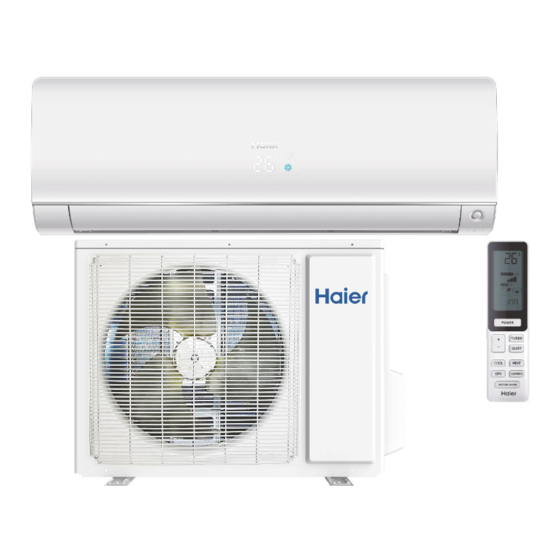
Ductless Split Heat Pump
Indoor
AW09EH2VHD
AW12EH2VHD
AW18EH2VHD
Please read this manual before installing this product.
Keep this user manual for future reference.
Table of Contents
Outdoor
1U09EH2VHD
1U12EH2VHD
1U18EH2VHD
PAGE 1
Advertisement
Table of Contents

Related Manuals for Haier AW09EH2VHD


Summary of Contents for Haier AW09EH2VHD
- Page 1 Ductless Split Heat Pump Indoor Outdoor AW09EH2VHD 1U09EH2VHD AW12EH2VHD 1U12EH2VHD AW18EH2VHD 1U18EH2VHD Service Manual Please read this manual before installing this product. Design may vary b y model number. Keep this user manual for future reference. ● Table of Contents Safety Precautions/Introduction....................3...
- Page 2 [This page intentionally left blank.]...
- Page 3 Introduction Table of Contents Safety Precautions ................................4 Warnings and Cautions ..................................4 Introduction to System ..............................5 ........................5 System Fundamentals..................................5 INTRODUCTION PAGE 3...
- Page 4 Failure to follow any CAUTION may in some cases result in grave consequences.
- Page 5 Introduction Introduction to System The inverter compressor system in the outdoor unit will vary Single Zone Ductless Split System Heat Pumps feature a wall the comfort requirement inside the conditioned space. If an mounted indoor fan/evaporator unit that receives refrigerant abnormal condition is detected by the system’s sensors, the from an inverter driven variable speed outdoor condensing system has the ability to take reactive measures.
- Page 6 PAGE 6...
- Page 7 Outdoor Unit Controls and Components Table of Contents Outdoor Unit Introduction ..............................8 ............................ Outdoor Main Control Boa rd .............................. 9 Terminal Block .................................. 10 ● Reactor .................................... 10 Compressor ..................................10 Outdoor Fan Motor ................................10 Discharge Temperature Sensor ............................11 Defrost Temperature Sensor ............................
- Page 8 Outdoor Unit Introduction The outdoor unit has two circuit boards, drives the compressor and main control an Inverter Power Module (IPM) that board (PCB) that manages system functions and inverter calculations. Sensors monitor key temperatures throughout the system to manage operational decisions. 4-Way Valve Accumulator Compressor...
- Page 9 5VDC and 15VDC pulsing communication connection between the PCB and the IPM ●...
- Page 15 Connector for coil temperature sensor and room temperature sensor ●...
- Page 16 Terminal Block Ambient Temperature Sensor The unit terminal block receives electrical power from the The Ambient (room) Temperature Sensor is a negative outdoor unit. There are 4 connections for electrical wires. thermistor that will decrease in resistance with Terminals 1 and 2 are connected to terminals 1 and 2 of the increases in room air temperature.
-
Page 18: Dip Switch
DIP Switch DIP Switch Settings The PCB has a set of DIP switches that must be set when replacing the PCB. ● The replacement PCB is shipped with all switches set to the OFF position. ● Switch settings: J5 Selects remote code A or B. Normally set to connection state for code A operation. -
Page 20: System Power
Indoor Unit System Power To enter the cool mode, point the infrared remote control at The 230 Volt AC power for the system connects to terminals the indoor unit and press the power button, then press the 1(N), 2(L), and ground of the outdoor unit terminal block. This COOL mode button if not already set to cool mode. -
Page 21: Heat Mode
operating parameter and the call is communicated from the The outdoor unit main board also controls the position of the indoor unit to the outdoor unit. EEV (Electronic Expansion Valve) to regulate the ow of refrigerant to the indoor unit evapora- The indoor unit louver will open using a stepper motor. -
Page 24: Protection Functions
Tempe rature Sensors Four temperature sensors located in the outdoor unit provide information to the outdoor unit PCB for control of the system Upon exiting the defrost cycle, the following conditions will take place: The outdoor ambient temperature sensor provides the temperature of the air drawn into the condenser c The defrost temperature sensor provides the temperature sensed at the output of the condenser c... - Page 25 3. Compressor Ov O er-current Protection If the current draw of the compressor at start-up is greater than the values listed on the chart below for approximately 3 seconds, the compressor will stop. After 3 minutes the 52°F // / / compressor will restart.
- Page 26 PAGE 32...
-
Page 27: System Specifications
System System M odel Name Outdoor 1U09EH2VHD 1U12EH2VHD 1U18EH2VHD Indoor AW09EH2VHD AW12EH2VHD AW18EH2VHD Rated Capacity Btu/hr 9,000 12,000 18,000 Capacity Range Btu/hr 3100~12000 3100~15000 8,500~21000 Rated Power Input W 1,385 Cooling SEER 16.0 15.0 13.0 M oisture Removal Pt./h 0.60 1.60... - Page 28 Check This First Outdoor Unit ................................29 Check This First Indoor Unit ................................30 Check This First - Indoor Unit Wiring Diagram Reference..................................31 Error Code (Indoor/Outdoor) F1/LED1: 2 Flash IPM Power Module Failure (IPM power module protection)................................32 Error Code: F1/LED1: 2 Flash................................33 Wiring Diagram Reference Error Code (Indoor/Outdoor) F2/LED1: 24 Flash Overcurrent of the Compressor................
-
Page 29: Check This First
Conditions Needed for Basic Operation Check This First Outoor Unit Models: 1U09EH2VHD Line voltage available at: • 1 (N) and 3 (C): 0-80 1U12EH2VHD 1. TERMINAL STRIP - 1(N) & 2 (L) 1U18EH2VHD • 2 (L) and 3 (C): 2. AC-L & AC-N at the PCB - CN2 & CN1 3. -
Page 30: Error Codes And Troubleshooting
Check This First Indoor Unit There is 230 VAC (+/- 10%) at terminal Models: AW09EH2VHD no more than a 2% deviation between AW12EH2VHD AW18EH2VHD There is a pulsing 0 to 80 power from OD unit or phase VAC between terminal strip... - Page 31 Check This First - Indoor Unit Wiring Diagram Reference ● Sensor Resistance Table ...
- Page 32 Error Code Start (Indoor/Outdoor) F1/LED1: 2 Flash IPM Power Module Fail (IPM power module protection) Complete the “Check This First” Flow Chart before continuing. Models: AW09EH2VHD AW12EH2VHD AW18EH2VHD 1U09EH2VHD 1U12EH2VHD 1U18EH2VHD Compressor runs for 10 min. Normal operation PAGE 32 ERROR CODES and Troubleshooting ●...
- Page 33 Error Code: F1/LED1: 2 Flash Wiring Diagram Reference OUTDOOR UNIT WIRING DIAGRAM 0011509127 COMPRESSOR EEV Resistance Values EEV (6-pin, 5 wire) EEV (6-pin, 6 wire) ...
-
Page 34: Error Code
(Indoor/Outdoor) Start F2/LED1: 24 Flash Overcurrent of the Compressor The set temperature is 5°F max. Complete the “Check This First” Flow Chart before continuing. Models: AW09EH2VHD AW12EH2VHD AW18EH2VHD 1U09EH2VHD 1U12EH2VHD 1U18EH2VHD Change set temperature Continue to monitor; the system is starting under an abnormal load ●... - Page 35 Error Code: F2/LED1: 24 Flash Wiring Diagram Reference OUTDOOR UNIT WIRING DIAGRAM 0011509127 COMPRESSOR COMPRESSOR COMPRESSOR PAGE 35 ERROR CODES and Troubleshooting ●...
- Page 36 F3/LED1: 4 Flash Line voltage at AC-L & AC-N Communication Fault Between IPM and Outdoor PCB Complete the “Check This First” Flow Chart before continuing. Models: AW09EH2VHD Line voltage at AW12EH2VHD from building AC-L OUT & AC-N AW18EH2VHD OUT on the PCB...
- Page 37 Error Code: F3/LED1: 4 Flash Wiring Diagram Reference OUTDOOR UNIT WIRING DIAGRAM 0011509127 COMPRESSOR ● PAGE 37 ERROR CODES and Troubleshooting ●...
- Page 38 Error Code (Indoor/Outdoor) F4/LED1: 8 Flash Overheat Protection For Discharge Temperature Complete the “Check This First” Flow Chart before continuing. Models: AW09EH2VHD AW12EH2VHD AW18EH2VHD 1U09EH2VHD 1U12EH2VHD 1U18EH2VHD ● remove moisture and with fresh refrigerant to nameplate amount ● refrigerant ●...
- Page 39 Error Code: F4/LED1: 8 Flash Wiring Diagram Reference OUTDOOR UNIT WIRING DIAGRAM 0011509127 ● COMPRESSOR EEV Resistance Values EEV (6-pin, 5 wire) EEV (6-pin, 6 wire) ...
- Page 40 Room Temperature Sensor Failure E2/LED1: No Flash Indoor Coil Temperature Sensor Failure (See Reverse side.) Complete the “Check This First” Flow Chart before continuing. Models: AW09EH2VHD AW12EH2VHD Go to next step AW18EH2VHD to test the board as well before 1U09EH2VHD...
- Page 41 Error Code: F6/LED1: 12 Flash, F7/LED1: 11 Flash, F21/LED1: 10 Flash, F25/LED1: 13 Flash, E1/LED1: No Flash, E2/LED1: No Flash Wiring Diagram Reference OUTDOOR UNIT WIRING DIAGRAM 0011509127 ● COMPRESSOR Sensor Resistance Table ...
- Page 42 Error Code (Indoor/Outdoor) F8/LED1: 9 Flash Start Outdoor DC Fan Motor Fault Complete the “Check This First” Flow Chart before continuing. Models: AW09EH2VHD AW12EH2VHD AW18EH2VHD 1U09EH2VHD 1U12EH2VHD 1U18EH2VHD ● Measure DC voltage at fan motor plug CN21 Re-apply power. Does the between Pin 1 (RED) and Pin 3 (BLACK).
- Page 43 Error Code: F8/LED1: 9 Flash Wiring Diagram Reference OUTDOOR UNIT WIRING DIAGRAM 0011509127 COMPRESSOR ● ERROR CODES and Troubleshooting GE 43 ●...
- Page 44 Error Code (Indoor/Outdoor) F11/LED1: 18 Flash Loss of Compressor Synchronization Complete the “Check This First” Flow Chart before continuing. Models: AW09EH2VHD AW12EH2VHD AW18EH2VHD Momentary loss A windings or grounding of building power 1U09EH2VHD 1U12EH2VHD power quality 1U18EH2VHD There is 50-200 VAC ●...
- Page 45 Error Code: F11/LED1: 18 Flash Wiring Diagram Reference OUTDOOR UNIT WIRING DIAGRAM 0011509127 ● COMPRESSOR ERROR CODES and Troubleshooting PAGE 45 ●...
- Page 46 Error Code (Indoor/Outdoor) F12/LED1: 1 Flash EEPROM Error After 10 minutes with the power Complete the “Check This First” Flow Chart before continuing. Models: AW09EH2VHD AW12EH2VHD ● AW18EH2VHD The 10-minute 1U09EH2VHD reboot has 1U12EH2VHD ● 1U18EH2VHD issue Wiring Diagram Reference...
- Page 47 (Indoor/Outdoor) E5/LED1: 22 Flash Coil Frost Protection There is 5 VDC at CN6 on the Indoor Complete the “Check This First” Flow Chart before continuing. Models: AW09EH2VHD AW12EH2VHD The Coil and Ambient AW18EH2VHD within 3% of the value 1U09EH2VHD 1U12EH2VHD 1U18EH2VHD ●...
- Page 48 Error Code: E5/LED1: 22 Flash Wiring Diagram Reference Sensor Resistance Table ...
- Page 49 (Indoor/Outdoor) E7/LED1: 15 Flash ID and OD Loss of Communication Complete the “Check This First” Flow Chart for both ID and OD units before continuing. Models: AW09EH2VHD AW12EH2VHD Is the Indoor PCB LED AW18EH2VHD 1U09EH2VHD 1U12EH2VHD 1U18EH2VHD Is the voltage from...
- Page 50 Error Code: E7/LED1: 15 Flash Wiring Diagram Reference ERROR CODES and Troubleshooting PAGE 50...
- Page 51 Error Code: E7/LED1: 15 Flash Wiring Diagram Reference OUTDOOR UNIT WIRING DIAGRAM 0011509127 COMPRESSOR ERROR CODES and Troubleshooting PAGE 51 ●...
- Page 52 Error Code Start (Indoor) Indoor Fan Motor Failure Complete the “Check This First” Flow Chart before continuing. Models: AW09EH2VHD AW12EH2VHD AW18EH2VHD the fan by hand. Does it power supply motor ● Measure DC voltage at fan Re-apply power. Does the motor plug CN9 between Pin 1 (RED) and Pin 4 (BLACK).
- Page 53 Error Code: E14 Wiring Diagram Reference ERROR CODES and Troubleshooting PAGE 5 ●...
- Page 54 Ductless Troubleshooting The resistance value of the coil should be 1.2 kilo ohms to Checking System Components 1.8 kilo ohms. Replace the valve c NOTE: Component resistance readings shown in this section are for reference only. Actual resistance values may based on model being tested.
- Page 55 Disconnect the sensor from the PCB for this test. Failure to do so may provide inaccurate readings. Step 2 Determine the temperature of the sensor being tested. AGE 55 ERROR CODES and Troubleshooting Haier Ductless Technical Support Phone: 866.814.3633 (option 3) Email: ductlesshelp@geappliances.com Online: www.HaierDuctlessHelp.com ● Rev. 04-20...
- Page 56 594.3 Ohm 594.5 Ohm Pink 594.3 Ohm Blue Step 3 Re-seat the plug on the PCB at the conclusion of the test. ERROR CODES and Troubleshooting PAGE 56 Haier Ductless Technical Support Phone: 866.814.3633 (option 3) Email: ductlesshelp@geappliances.com Online: www.HaierDuctlessHelp.com ● Rev. 04-20...
- Page 57 Ambient, Defrost, and Pipe Sensor Tables Discharge Sensor Tables PAGE 57...
-
Page 58: Outdoor Board Diagram
Outdoor Board Diagram OUTDOOR UNIT WIRING DIAGRAM 0011509127 COMPRESSOR Electrical Shock Hazard Riesgo de Descarga Eléctrica Risque de choc électrique Capacitor retains charge a er El capacitor re ene carga una vez Le condensateur conserve sa charge après la power is disconnected. Con rm desconectada la corriente. -
Page 59: Indoor Board Diagram
Indoor Board Diagram INDOOR UNIT DIAGRAM 0011509128 DC FAN MOTOR Diagnostic CN38 B:Black R:Red RJ45 port W:White BL:Blue Y:Yellow BR:Brown CN56 HUMAN SENSOR Y/G:Yellow/Green CN35 WIFI Unit SW1 DIP Switch CN21 position CN51 ROOM CARD 1 2 3 4 CN34 off off off off WK-B... - Page 60 Room and Coil Sensor Tables R77° = B77°/122° = F ° °C Tolerance (°C) 165.217 147.9497 132.3678 -1.94 1.75 -20.2 155.5754 139.56 125.0806 -1.93 1.74 -18.4 146.5609 131.7022 118.2434 -1.91 1.73 -16.6 138.1285 124.3392 111.8256 -1.89 1.71 -14.8 130.2371 117.4366 105.7989 -1.87 122.8484...
- Page 61 Room and Coil Sensor Tables F ° °C Tolerance (°C) 62.6 14.5748 14.0079 13.451 -0.93 0.92 64.4 13.9436 13.4185 12.9017 -0.91 66.2 13.3431 12.8572 12.3778 -0.88 0.87 12.7718 12.3223 11.878 -0.86 0.85 69.8 12.228 11.8126 11.4011 -0.83 0.83 71.6 11.7102 11.3267 10.9459 -0.81...
- Page 62 Room and Coil Sensor Tables F ° °C Tolerance (°C) 2.4591 2.284 2.1195 -2.36 2.21 150.8 2.3815 2.2098 2.0486 -2.4 2.25 152.6 2.3068 2.1383 1.9803 -2.45 2.29 154.4 2.2347 2.0695 1.9147 -2.49 2.34 156.2 2.1652 2.0032 1.8516 -2.54 2.38 2.0983 1.9393 1.7908 -2.59...
- Page 63 Room and Coil Sensor Tables F ° . °C Tolerance (°C) 235.4 0.62 0.5518 0.4907 -4.86 4.36 237.2 0.6043 0.5374 0.4775 -4.92 4.41 0.5891 0.5235 0.4648 -4.98 4.45 240.8 0.5743 0.51 0.4524 -5.04 242.6 0.56 0.4968 0.4404 -5.1 4.55 244.4 0.546 0.4841 0.4288...
- Page 64 Ambient , Defrost and Pipe Sensor Tables F ° °C Tolerance (°C) 23.0284 21.8398 20.6939 -1.18 1.14 21.9714 20.8659 19.7982 -1.15 1.12 20.9688 19.9409 18.9463 -1.13 1.09 20.0176 19.0621 18.1358 -1.11 1.07 ● 19.1149 18.2270 17.3646 -1.08 1.05 ● 18.2580 17.4331 16.6305 -1.06...
- Page 65 Ambient , Defrost and Pipe Sensor Tables F ° °C Tolerance (°C) (°C) 3.4195 3.2085 3.0079 -1.91 1.82 3.3060 3.0989 2.9021 -1.95 1.85 3.1969 2.9935 2.8005 -2.00 1.89 3.0919 2.8922 2.7029 -2.04 1.93 2.9909 2.7948 2.6092 -2.08 1.97 2.8936 2.7012 2.5193 -2.13 2.01...
-
Page 66: Sensor Tables
Ambient , Defrost and Pipe Sensor Tables F ° °C Tolerance (°C) 0.8061 0.7233 0.6484 -4.29 3.88 0.7848 0.7036 0.6303 -4.34 3.92 0.7641 0.6845 0.6127 -4.40 3.97 0.7441 0.6661 0.5957 -4.46 4.02 0.7247 0.6482 0.5792 -4.51 4.07 0.7059 0.6308 0.5632 -4.57 4.12 0.6877... - Page 67 Discharge Sensor Tables Temp.(°F) Temp.(°C) Tolerance 24.8 2738.6777 2368.3158 2046.1961 -2.6 2.26 26.6 2581.6752 2236.3876 1935.5371 -2.58 2.25 28.4 2434.5487 2112.5459 1831.4826 -2.56 2.24 30.2 2296.623 1996.2509 1733.6024 -2.55 2.23 2167.273 1887.0018 1641.4966 -2.53 2.22 33.8 2045.9191 1784.3336 1554.7931 -2.52 2.21 35.6 1932.0242...
- Page 68 Discharge Sensor Tables Temp.(°F) Temp.(°C) Tolerance 218.386 203.2887 189.0648 -1.67 1.57 114.8 208.7855 194.6066 181.2273 -1.65 1.55 116.6 199.6531 186.3369 173.7524 -1.63 1.54 118.4 190.9639 178.4584 166.6217 -1.6 1.52 120.2 182.6945 170.9508 159.8181 -1.58 174.8228 163.7951 153.3249 -1.56 1.48 123.8 167.328 156.9733 147.1268...
- Page 69 Discharge Sensor Tables Temp.(°F) Temp.(°C) Tolerance 201.2 31.8302 30.4467 29.097 -1.33 30.7933 29.4246 28.0915 -1.37 1.34 204.8 29.795 28.4417 27.1254 -1.41 1.37 206.6 28.8337 27.4961 26.197 -1.45 1.41 208.4 27.9078 26.5864 25.3048 -1.49 1.44 210.2 27.016 25.711 24.447 -1.53 1.48 26.1569 24.8685 23.6222...
- Page 70 ● Model #: AW09EH2VHD, 1U09EH2VHD AW12EH2VHD, 1U12EH2VHD ● AW18EH2VHD, 1U18EH2VHD Haier America, Wayne, NJ 07470 ● Issued Date: November 2020 ©2020Haier America Trading, LLC.
Need help?
Do you have a question about the AW09EH2VHD and is the answer not in the manual?
Questions and answers