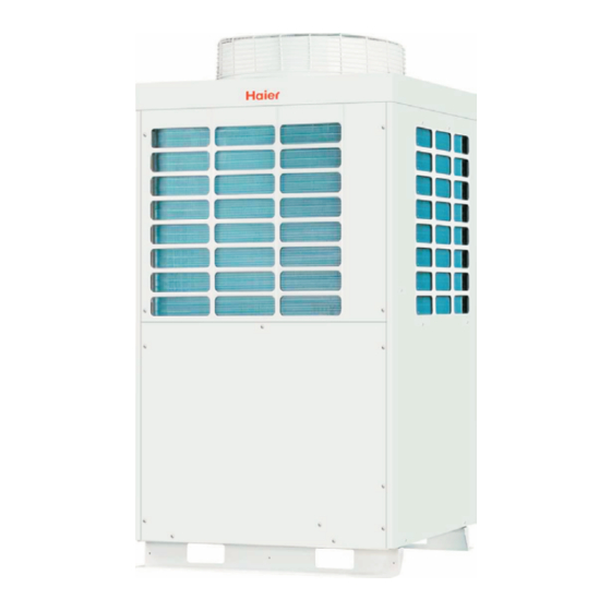
Haier MRV II AV08NMVERA Startup Manual
R410a heat pump 50hz
Hide thumbs
Also See for MRV II AV08NMVERA:
- Installation manual (135 pages) ,
- Manual (129 pages) ,
- Startup manual (40 pages)
Advertisement
Quick Links
START UP GUIDE
R410A HEAT PUMP 50HZ
SYJS-005-08REV.0
MRV II
AV08NMVERA
AV10NMVERA
AV12NMVERA
AV14NMVERA
AV16NMVERA
AV18NMVERA
AV20NMVERA
AV22NMVERA
AV24NMVERA
AV26NMVERA
AV28NMVERA
AV28NMVERA
AV30NMVERA
AV32NMVERA
AV34NMVERA
AV36NMVERA
AV38NMVERA
AV40NMVERA
AV42NMVERA
AV44NMVERA
AV46NMVERA
AV48NMVERA
Aug. 2008
Advertisement

Summary of Contents for Haier MRV II AV08NMVERA
- Page 1 MRV II START UP GUIDE R410A HEAT PUMP 50HZ AV08NMVERA AV28NMVERA AV10NMVERA AV30NMVERA AV12NMVERA AV32NMVERA AV14NMVERA AV34NMVERA AV16NMVERA AV36NMVERA AV18NMVERA AV38NMVERA AV20NMVERA AV40NMVERA AV22NMVERA AV42NMVERA AV24NMVERA AV44NMVERA AV26NMVERA AV46NMVERA AV28NMVERA AV48NMVERA SYJS-005-08REV.0 Aug. 2008...
- Page 3 1. Lineup of MRVII system 1.1 Indoor/outdoor models Indoor units Outdoor units...
-
Page 4: External Appearance
1.2 External appearance... -
Page 6: Wiring Work
2. Wiring work... - Page 7 2.1 Confirm the power cables' connection of each indoor unit...
- Page 8 2.2 Confirm the communication wires' connection of each indoor unit...
- Page 9 2.3 Confirm the wired controller wires connection of each indoor unit...
- Page 10 2.3 Confirm the wired controller wires connection of each indoor unit...
- Page 11 2.4 Confirm the wiring connection when in central control...
- Page 12 2.5 Confirm the central controller setting Note:...
- Page 13 2.6 Confirm the power cables' connection of each outdoor 2.7 Confirm the P, Q connection and the communication among outdoors A, B, C connection...
- Page 14 2.8 Confirm the indoor control type 2.9 Confirm the indoor communication address when in central control: SW03 on indoor PCB...
- Page 15 2.10 Confirm the indoor central control address when in central control: SW02 on indoor PCB...
- Page 16 2.11 Confirm the indoor group control address when in group control: SW01 on indoor...
- Page 17 2.12 Confirm the outdoor pipe length switch on outdoor PCB SW4-1 SW4-2 2.13 Confirm the outdoor capacity over match switch setting on outdoor PCB...
- Page 18 2.14 Confirm the outdoor unit address: the master unit must be No. 1. 2.15 Confirm the outdoor units searching when multi units in combination...
- Page 19 2.16 Confirm the outdoor capacity SW2-1 SW2-2 SW2-3...
- Page 20 2.17 Rotary switch function 2.17.1 Check indoor parameters by rotary switch...
- Page 21 2.17.2 Check outdoor parameters by rotary switch...
- Page 22 2.17.3 Inverter unit information center: display parameters of the whole system...
- Page 23 WARNING: In the above table, after debugging, MUST quit the set of 0, 13, 2/0, 14, 2. In normal operation, start up the unit from indoor unit, or the indoor will not stop even it has arrived the set temperature. 2.17.4 Inspection of inverter control parts...
- Page 24 WARNING: In the above table, 6, 8, 2/6, 9, 2/6, 10, 2/6, 11, 2 are FORBIDDEN TO BE USED IN DEBUGGING.
- Page 25 3. Indoor unit control £ 2¡ ¡ 2¡ £…16¡...
- Page 26 ¡ ¡ ¡ ¡ 3.2 Wired controller ¡œ ¡œ ¡œ...
- Page 27 Buttons description: ¡œ ¡œ ¡œ ¡œ ¡œ ¡œ ¡œ ¡œ ¡œ ¡œ ¡œ...
- Page 29 3.3 Infrared controller YR-H71(for indoor unit excudes V-appearance wall mounted type) About Health functon: NOTE:For the indoor Wall Mounted and Cabinet units NOTE:For the Convertible and Cassette and console indoor units NOTE:For the Duct and Ceiling concealed indoor units...
- Page 30 The function of code B...
- Page 31 Loading the battery Replacing the battery compartment lid Display review Confirmation indicator Clock Set...
- Page 32 COOL , HEAT and DRY Operation...
- Page 33 Timer ON/OFF Function,(Set clock correctly before starting TIMER operation) Timer ON-OFF Function...
- Page 34 Health & Fresh Air operation Health operation About Health operation About Fresh air operation...
- Page 35 4. Outdoor control...
- Page 38 5. Dip switch setting when out of factory: Dip switch setting of outdoor connecting board when out of factory: Dip switch setting of indoor PCB when out of factory:...
- Page 39 6. Wiring of indoor and outdoor Wiring of indoor units (for example) Wiring of outdoor units (for example)


Need help?
Do you have a question about the MRV II AV08NMVERA and is the answer not in the manual?
Questions and answers