Table of Contents
Advertisement
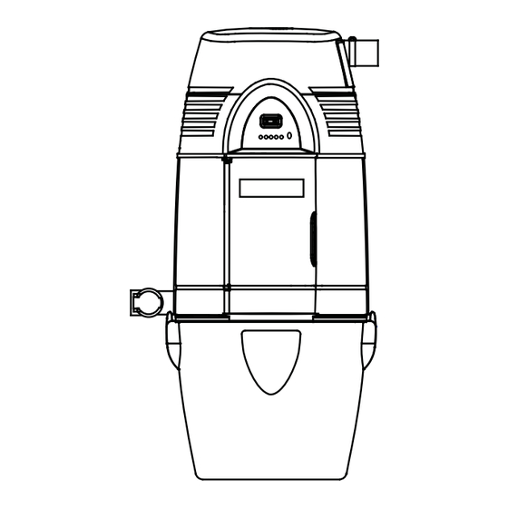
CENTRAL VACUUM SYSTEM
Broan Power Unit Models VX3000C, VX6000C, VX12000C
NuTone Power Unit Models VX475CC, VX550CC, VX1040CC
SYSTEM PLANNING AND LAYOUT . . . . . . . . . . . . . . . . . . . . . . . . . . . . . . . 2-3
Examples . . . . . . . . . . . . . . . . . . . . . . . . . . . . . . . . . . . . . . . . . . . . . . . . 2-3
Locating the Power Unit . . . . . . . . . . . . . . . . . . . . . . . . . . . . . . . . . . . . . . 3
Tubing and Wall Inlet Locations . . . . . . . . . . . . . . . . . . . . . . . . . . . . . . . . 3
GENERAL INSTALLATION . . . . . . . . . . . . . . . . . . . . . . . . . . . . . . . . . . . . . . . 4
Tool Listing . . . . . . . . . . . . . . . . . . . . . . . . . . . . . . . . . . . . . . . . . . . . . . . . . 4
Working with Plastic Tubing . . . . . . . . . . . . . . . . . . . . . . . . . . . . . . . . . . . . 4
INSTALLATION IN NEW CONSTRUCTION . . . . . . . . . . . . . . . . . . . . . . . . . 5-6
Wall Inlet Rough-In . . . . . . . . . . . . . . . . . . . . . . . . . . . . . . . . . . . . . . . . . . 5
Installing the Tubing . . . . . . . . . . . . . . . . . . . . . . . . . . . . . . . . . . . . . . . . 5-6
Wall Inlet Installation . . . . . . . . . . . . . . . . . . . . . . . . . . . . . . . . . . . . . . . . . 6
INSTALLATION IN EXISTING CONSTRUCTION . . . . . . . . . . . . . . . . . . . . 7-11
Locating Access Keys in Existing Construction . . . . . . . . . . . . . . . . . . . . . 7
Avoiding In-Wall Obstacles . . . . . . . . . . . . . . . . . . . . . . . . . . . . . . . . . . . . 7
Inlet Tubing Installation . . . . . . . . . . . . . . . . . . . . . . . . . . . . . . . . . . . . . . 7-9
Wall Inlet Installation . . . . . . . . . . . . . . . . . . . . . . . . . . . . . . . . . . . . . . . 9-11
®
INLET VALVE INSTALLATION . . . . . . . . . . . . . . . . . . . . 12-14
Connection From Below . . . . . . . . . . . . . . . . . . . . . . . . . . . . . . . . . . . . . .12
Connection From Behind . . . . . . . . . . . . . . . . . . . . . . . . . . . . . . . . . . . . .13
Connection In a Wall . . . . . . . . . . . . . . . . . . . . . . . . . . . . . . . . . . . . . .13-14
TUBING SYSTEM ASSEMBLY . . . . . . . . . . . . . . . . . . . . . . . . . . . . . . . . . 15-17
POWER UNIT INSTALLATION . . . . . . . . . . . . . . . . . . . . . . . . . . . . . . . . . 18-20
Mounting . . . . . . . . . . . . . . . . . . . . . . . . . . . . . . . . . . . . . . . . . . . . . . . . . 18
Tubing Connections at Power Unit . . . . . . . . . . . . . . . . . . . . . . . . . . . . . 19
Dimensional Chart . . . . . . . . . . . . . . . . . . . . . . . . . . . . . . . . . . . . . . . . . . 19
Wiring . . . . . . . . . . . . . . . . . . . . . . . . . . . . . . . . . . . . . . . . . . . . . . . . . 19-20
FINAL SYSTEM CHECK . . . . . . . . . . . . . . . . . . . . . . . . . . . . . . . . . . . . . . . . . 20
TROUBLESHOOTING GUIDE . . . . . . . . . . . . . . . . . . . . . . . . . . . . . . . . . . . . 21
WARRANTY . . . . . . . . . . . . . . . . . . . . . . . . . . . . . . . . . . . . . . . . . . . . . . . . . . 22
Broan-NuTone Canada Inc.; Mississauga, Ontario
www.broan.ca or www.nutone.ca 866-882-7626
INSTALLATION INSTRUCTIONS
AB0004
30042319 rev. 09
Advertisement
Table of Contents

Subscribe to Our Youtube Channel
Related Manuals for NuTone VX3000C


Summary of Contents for NuTone VX3000C
-
Page 1: Table Of Contents
INSTALLATION INSTRUCTIONS CENTRAL VACUUM SYSTEM Broan Power Unit Models VX3000C, VX6000C, VX12000C NuTone Power Unit Models VX475CC, VX550CC, VX1040CC SYSTEM PLANNING AND LAYOUT ....... 2-3 Examples . -
Page 2: System Planning And Layout
page 2 SYSTEM PLANNING LAYOUT Central Vacuum Systems consist of a Power Unit, PVC Tubing and Fittings, Wall Inlets, a flexible Hose and various cleaning accessories. WARNING When applicable local regulations comprise more restrictive installation and/or certification requirements, the aforementioned requirements prevail on those of this document and the installer agrees to conform to these at his own expenses. -
Page 3: Locating The Power Unit
● Locate the power unit within 6 feet (1.82 m) of a grounded as few fittings as possible. electrical outlet. Broan models VX3000C and VX6000C and NuTone models VX475CC & VX550CC power units 3. Beginning at the area farthest from the power unit, choose require a 120 V, 15-amp dedicated branch circuit with a a tentative inlet location. -
Page 4: General Installation
page 4 GENERAL INSTALLATION TOOL LISTING Making a Joint Depending on your installation, you may require the use of Insert the tube into the these tools. The power tools are recommended to make your fitting, aligning the two installation proceed quickly. Also, plan a mask when cutting parts as they will be ducting (PVC dust) and gloves when using glue. -
Page 5: Installation In New Construction
page 5 INSTALLATION IN NEW CONSTRUCTION MODEL V144 WALL INLET MOUNTING PLATE 5. Run low-voltage wiring (Model V133) and secure wiring to tubing as tubing is installed. Model V140 Tubing Strap can (For use with V111 Series inlets) be used to support long runs of tubing (position near joists) and to clip wire along tubing. -
Page 6: Wall Inlet Installation
page 6 INSTALLATION IN NEW CONSTRUCTION (CONT’D) 9. Refer to Figure 14. Remove burrs from both inside and WALL INLET INSTALLATION outside of tubing. V111 Series Wall Inlet 10. Before cementing, pre-assemble section to inlet fitting, (V144 Mounting Plate) check for proper length. Refer to Figure 18. -
Page 7: Installation In Existing Construction
Refer to Figure 19. A laundry chute could also provide tools you will need to install your Broan or NuTone Central access from basement to upper floors. You may also want to Vacuum System. - Page 8 page 8 INSTALLATION IN EXISTING CONSTRUCTION (CONT’D) Enter the attic and find the inlet wall. Have a helper downstairs Drilling the Access Holes knock on the top of the wall right above the inlet location; Once you are certain that locate the general area by following the sound.
-
Page 9: Wall Inlet Installation
page 9 INSTALLATION IN EXISTING CONSTRUCTION (CONT’D) If space permits, you can Assemble and install the wall inlet as shown in the illustrations assemble the entire inlet line and as explained in the next few pages. Be careful and by joining two sections of patient as you make your first cutout and install your first tubing with a stop coupling inlet—following the procedure step by step—and the other... - Page 10 page 10 INSTALLATION IN EXISTING CONSTRUCTION (CONT’D) Also drill four pilot holes in Hold the assembly in a place for a few minutes as the cement Pilot holes must be the four corners of the sets; allow five minutes for the cement to completely dry. inside marked line marked area.
- Page 11 page 11 INSTALLATION IN EXISTING CONSTRUCTION (CONT’D) Installing the Inlet V111 Series Wall Inlet Installation (V144 Mounting Plate) When you place the inlet into the wall cutout, the 1. Make cutout according to dimensions in Figure 20. mounting plate and tube 2.
-
Page 12: Vacusweep Inlet Valve Installation
page 12 VACUSWEEP ® INLET VALVE INSTALLATION CONNECTION FROM BELOW Refer to Figure 24. 1. Turn the power to the vacuum unit OFF. Measure distance (X) between the CONNECTION FROM BELOW kickplate face and the inside edge of the cabinet. Then add 2¾” (70 mm) to the measured distance. -
Page 13: Connection From Behind
page 13 VACUSWEEP ® INLET VALVE INSTALLATION (CONT’D) CONNECTION FROM BEHIND 4. Using the reference hole as a center, cut a 2⅜” H x 6⅝” W (60 mm H x 168 mm W) rough opening in the kickplate Refer to Figure 25. face. - Page 14 page 14 VACUSWEEP ® INLET VALVE INSTALLATION (CONT’D) VacuSweep Inlet Valve Rough-in Template 5. Glue the long socket of the tight elbow (part no. V382XS) onto a section of 2” (51 mm) central vacuum tube. Make the terminal connections to the VacuSweep Inlet Valve by sliding the low-voltage wire into wire clips.
-
Page 15: Tubing System Assembly
page 15 TUBING SYSTEM ASSEMBLY Once you have installed all your inlets, you can complete the Beginning the Trunk Line network of tubing that connects your inlets to the power unit. Start the inlet line which is This network consists of the following parts: farthest from the power unit. - Page 16 page 16 TUBING SYSTEM ASSEMBLY (CONT’D) Connecting a Branch Line A branch line connects the inlet line to the trunk line. Follow the methods previously described for aligning, marking and cutting the inlet tubing. Attach a 90° elbow and run tubing from the inlet line to the trunk line.
- Page 17 page 17 TUBING SYSTEM ASSEMBLY (CONT’D) Run the low-voltage wiring along the trunk line; at approximately 12”-18” (305 mm - 457 mm) intervals, use electrical tape to secure the wire to the tubing. Then, run wiring along the branch lines from the inlet lines to the trunk line.
-
Page 18: Power Unit Installation
Refer to Page 3 for information on locating the power unit. 1. Locate power unit within six feet (1.82 m) of a grounded electrical outlet. Broan VX3000C & VX6000C and NuTone WARNING VX475CC & VX550CC power units require a 120 V, dedicated 15-amp branch-circuit with a NEMA 5-15R Do not install outdoors. -
Page 19: Tubing Connections At Power Unit
V127 Broan VX3000C & VX6000C and NuTone VX475CC & 2. Cap off the unused intake tube with the plastic cap provided. VX550CC are for use on a standard 120 VAC, dedicated 3. -
Page 20: Final System Check
Store the owner's manual with the cleaning tools and accessories. when hose is inserted and switched on, if applicable. If the Now it’s time to enjoy the benefits of a Broan or NuTone central vacuum hose is not available at the time, a short Central Vacuum System. -
Page 21: Troubleshooting Guide
2e. Microprocessor Lockup. Note: This would apply 2e. 1) Push Reset button while unit is only to Broan VX6000C & VX12000C and engaged OR NuTone VX550CC & VX1040CC. 2) Unplug unit completely for 60 seconds. 2f. Low line voltage. 2f. Contact your local electricity distributor. -
Page 22: Warranty
IMPLIED, INCLUDING, BUT NOT LIMITED TO, IMPLIED WARRANTIES OF MERCHANTABILITY OR FITNESS FOR A PARTICULAR PURPOSE. During these time periods, Broan-NuTone Canada will, at its option, repair or replace the power unit or part without charge, which is found to be defective under normal use and service.
Need help?
Do you have a question about the VX3000C and is the answer not in the manual?
Questions and answers