Table of Contents
Advertisement
Available languages
Available languages
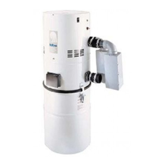
Built-In Central Cleaning System
MODEL: CV850
Examples . . . . . . . . . . . . . . . . . . . . . . . . . . . . . . . . . . . . . . . . . . . .2
Locating the Power Unit . . . . . . . . . . . . . . . . . . . . . . . . . . . . . . . . .3
Tubing and Wall Inlet Location . . . . . . . . . . . . . . . . . . . . . . . . . . .3
Locating Access Keys in Existing Construction . . . . . . . . . . . . . . .3
INSTALLATION IN NEW CONSTRUCTION . . . . . . . . . . . . . . . .4-8
Wall Inlet Rough-In . . . . . . . . . . . . . . . . . . . . . . . . . . . . . . . . . . . .4
Installing the Tubing . . . . . . . . . . . . . . . . . . . . . . . . . . . . . . . . . . . .5
Models CI370 & 360 Wall Inlets . . . . . . . . . . . . . . . . . . . . . . . . .6
Model 330 Wall Inlet . . . . . . . . . . . . . . . . . . . . . . . . . . . . . . . . .6
Model CI390 Wall Inlet (Electrified Inlet) . . . . . . . . . . . . . . . . . .7
POWER UNIT INSTALLATION . . . . . . . . . . . . . . . . . . . . . . . . . . .8
Dimensional Chart . . . . . . . . . . . . . . . . . . . . . . . . . . . . . . . . . . . .8
Mounting . . . . . . . . . . . . . . . . . . . . . . . . . . . . . . . . . . . . . . . . . . .8
Tubing Connections at Power Unit . . . . . . . . . . . . . . . . . . . . . . .8
Wiring . . . . . . . . . . . . . . . . . . . . . . . . . . . . . . . . . . . . . . . . . . . . . .8
INSTALLATION IN EXISTING CONSTRUCTION . . . . . . . . . . .9-10
Models CI370 & 360 Wall Inlets . . . . . . . . . . . . . . . . . . . . . . . . .9
Model 330 Wall Inlet . . . . . . . . . . . . . . . . . . . . . . . . . . . . . . . .10
FLOOR INLET INSTALLATION . . . . . . . . . . . . . . . . . . . . . . .10-11
FINAL SYSTEM CHECK . . . . . . . . . . . . . . . . . . . . . . . . . . . . . . . .11
WARRANTY . . . . . . . . . . . . . . . . . . . . . . . . . . . . . . . . . . . . . . . . .12
. . . . . . . . . . . . . . . . . . . . . .2
INSTALLATION
INSTRUCTIONS
Advertisement
Chapters
Table of Contents

Related Manuals for NuTone Advantage CV850


Summary of Contents for NuTone Advantage CV850
-
Page 1: Table Of Contents
Built-In Central Cleaning System MODEL: CV850 SYSTEM PLANNING AND LAYOUT Examples ..........2 Locating the Power Unit . -
Page 2: Examples
SYSTEM PLANNING AND LAYOUT The NuTone Central Cleaning System consists of a Power Unit, PVC Tubing and Fittings, Wall Inlets, a flexible Hose and various cleaning Attachments. The Power Unit is designed to be wall-mounted away from the living area of the home and connected to the living area by means of permanently installed in-wall tubing, fittings and inlets. -
Page 3: Locating The Power Unit
LOCATING THE POWER UNIT • Locate the power unit away from the general living area in an accessible location for changing the soil bag and periodically cleaning the secondary filter. • When planning, remember the power unit is equipped with an inlet to service a garage, basement, utility room, etc., wherever it is located. -
Page 4: Installation In New Construction
INSTALLATION IN NEW CONSTRUCTION WALL INLET ROUGH-IN Once the locations for wall inlets have been determined, mount all inlet brackets. 1. Choose the appropriate mounting bracket for the inlet being installed. (See chart.) NuT one Inlet 330 Series 360 Series CI370 Series Indicating Inlet CI390 Series Electrified Inlet 2. -
Page 5: Installing The Tubing
INSTALLATION IN NEW CONSTRUCTION INSTALLING THE TUBING Use the following installation guidelines when installing tubing. Start tubing installation at farthest inlet and work toward the power unit. Tubing run to the power unit should be as straight as possible. When assembling sections with elbows and tees, make sure the curve in the fitting is aligned so that the air flows toward the power unit. -
Page 6: Wall Inlet Installation
INSTALLATION IN NEW CONSTRUCTION WALL INLET INSTALLATION Your CV850 Power Unit is designed especially for model CI370 Series Indicating Inlets. These inlets include a LED to remind you after 25 hours of operation that it is time to change the filter bag in your power unit. - Page 7 INSTALLATION IN NEW CONSTRUCTION CI-390 ELECTRAVALVE™ ELECTRIFIED INLET INSTALLATION (CI-390RK Rough-In) (Not available in Canada) 1. See Figure 24. Fasten the mounting plate to a stud within three studs (48") of an electrical outlet box. Measure and mark the wire 10" from the plug (A). Feed the wire through the top hole in the mounting plate (just above the circular opening).
-
Page 8: Power Unit Installation
POWER UNIT INSTALLATION MINIMUM WALL CLEARANCE DIMENSIONS 12" EXHAUST “D” TOP VIEW Note: The Power Unit utilizes two (2) mufflers that may be 12" MINIMUM TO CEILING FRONT VIEW “B” TOP OF UNIT TO KEYHOLE SLOT EXHAUST “A” INTAKE OVERALL HEIGHT 18"... -
Page 9: Installation In Existing Construction
INSTALLATION IN EXISTING CONSTRUCTION Use the following procedures for installation in existing construction. Starting from farthest wall inlet location, install each inlet as described below. Working back toward power unit, connect each inlet line and branch line into main trunk line. See page 5. Complete low voltage wiring as main trunk line is continued back to power unit. -
Page 10: Installation In Existing Construction
INSTALLATION IN EXISTING CONSTRUCTION MODEL 330N WALL INLET INSTALLATION (329 Rough-in) 1. Make cutout according to dimensions in Figure 35. 2. Refer to Figure 36. Break off nail plate at scored line. 3. Refer to Figure 37. Glue elbow to mounting plate, place assembly into cutout, and attach elbow to tubing inside the wall. -
Page 11: Floor Inlet Installation
FLOOR INLET INSTALLATION FLOOR INLET INLET EXTENSION " FLOOR SUB-FLOOR MOUNTING BRACKET FIGURE 41 FINAL SYSTEM CHECK Be sure all inlets are closed and soil bag is in place. Check switch on power unit for manual on/off operation. Check that indicator light on side of power unit is lit and is in green mode. -
Page 12: Warranty
Residents of Alaska or Hawaii should write to: NuTone Inc. Attn: Department of National Field Service, 4820 Red Bank Road, Cincinnati Ohio 45227-1599. Residents of Canada should write to: Broan-NuTone Canada, 1140 Tristar Drive, Mississauga, Ontario, Canada L5T 1H9. ®... -
Page 13: Instructions D'installation
Système Central d’Aspiration Intégré MODELE: CV850 PLANIFICATION ET DISPOSITION DU SYSTEME ...2 Exemples ..........2 Emplacement du Groupe d’Aspiration . -
Page 14: Planification Et Disposition Du Systeme
PLANIFICATION ET DISPOSITION DU SYSTEME Le système central d'aspiration intégré de NuTone comprend un groupe d'aspiration, une tuyauterie et des raccords en PVC, des prises d'aspiration murales, un tuyau souple et de différents accessoires de nettoyage. Le Groupe d'Aspiration est conçu pour un montage mural éloigné de la zone d'habitation de la maison mais connecté... -
Page 15: Emplacement Du Groupe D'aspiration
EMPLACEMENT DU GROUPE D’ASPIRATION • Installez le groupe d'aspiration éloigné de la zone d'habitation dans un lieu facile d'accès pour changer le sac à poussière et nettoyer périodiquement le filtre secondaire. • Lors de votre planification, rappelez-vous que le groupe d'aspiration est équipé... -
Page 16: Installation Dans Une Nouvelle Construction
INSTALLATION DANS UNE NOUVELLE CONSTRUCTION ENCASTREMENT DE PRISE MURALE Une fois l'emplacement des prises murales déterminé, mettez en place tous les supports de prise. 1. Choisissez les supports de fixation appropriés pour la prise à installer. (Voyez le tableau). Prises NuT one Série 330 Série 360 Série CI370 Prise avec voyant lumineux 361... -
Page 17: Installation De La Tuyauterie
INSTALLATION DANS UNE NOUVELLE CONSTRUCTION INSTALLATION DE LA TUYAUTERIE Suivez les lignes directrices ci-dessous lors de la mise en place de la tuyauterie. Commencez l'installation de la tuyauterie par la prise la plus éloignée et avancez vers le groupe d'aspiration. La tuyauterie qui rejoint le groupe d'aspiration devrait être la plus droite possibe. -
Page 18: Installation Des Prises Murales
INSTALLATION DANS UNE NOUVELLE CONSTRUCTION (suite) INSTALLATION DES PRISES MURALES Votre groupe d'aspiration CV850 est spécialement conçu pour le modèle CI 370 de série de prises dotées d'un voyant lumineux. Ces prises incluent un DEL pour vous rappeler que, après chaque 25 heures d'utilisation, il est temps de changer le sac de votre groupe d'aspiration. - Page 19 INSTALLATION DANS UNE NOUVELLE CONSTRUCTION (suite) INSTALLATION DE LA PRISE ELECTRIFIEE ELECTRAVALVE™ CI--390 ( ENCASTREMENT CI-390RK) (NON DISPONIBLE AU CANADA) 1. Voyez la figure 24. Attachez la plaque de montage à un montant à une distance maximum de trois montants (1,22 m) d'un coffret de sortie électrique.
-
Page 20: Installation Du Groupe D'aspiration
INSTALLATION DU GROUPE D'ASPIRATION ESPACE AU MUR MINIMUM 45,7 cm 30,5 cm EVACUATION “D” VUE DE DESSUS NOTA: LE GROUPE D'ASPIRATION UTILISE DEUX (2) SILENCIEUX QUI PEUVENT ETRE DISPOSES EN HAUT, BAS OU HORIZONTALEMENT A 30,5 cm MINIMUM DU PLAFOND VUE DE FACE “B”... -
Page 21: Installation Dans Une Construction Existante
INSTALLATION DANS UNE CONSTRUCTION EXISTANTE Utilisez les procédures suivantes pour une installation dans une construction existante. En commençant par la prise murale la plus éloignée, installez chaque prise tel qu' il vous est décrit ci-dessous. Travaillez vers le groupe d'aspiration; connectez chaque ligne de prise et ligne secondaire à... - Page 22 INSTALLATION DANS UNE CONSTRUCTION EXISTANTE (suite) INSTALLATION DE PRISE MURALE MODELE 330N (ENCASTREMENT 329) 1. Faites la découpe en accord avec les dimensions de la Figure 35. 2. Voyez la Figure 36. Détachez la plaque suivant les pointillés. 3. Voyez la Figure 37. Collez le coude à la plaque de montage, placez l'ensemble dans la découpe, et attachez le coude à...
-
Page 23: Installation Des Prises Au Sol
INSTALLATION DES PRISES AU SOL FLOOR PRISE DE INLET PLANCHER INLET EXTENSION DE EXTENSION PRISE 6,51 cm " PLANCHER FLOOR SUB-FLOOR SOUS-PLANCHER MOUNTING SUPPORT DE MONTAGE BRACKET FIGURE 41 VERIFICATION FINALE DU SYSTEME Assurez-vous que toutes les prises sont fermées et que le sac à poussière est en place. - Page 24 Garder à protée de la main le numéro du modèle, la date et la preuve d’achat, le type de problème. Résidents de l’Alaska et d’Hawaii: Écrivez à NuTone Inc. Attn: Department of National Field Service, 4820 Red Bank Road, Cincinnati Ohio USA 45227-1599. Résidents du Canada: Écrivez à Broan-NuTone Canada, 1140 Tristar Drive, Mississauga, Ontario Canada L5T 1H9. ®...
- Page 25 Sistema de aspiración central empotrado MODELO: CV850 PLANIFICACION Y DIAGRAMAS Ejemplos ..........2 Ubicación de la unidad de potencia .
-
Page 26: Planificacion Y Diagramas
PLANIFICACION Y DIAGRAMAS El Sistema de aspiración central de NuTone consiste de una unidad de potencia, entubado y conectores de PVC, enchufes de pared, una manguera flexible y varios accesorios de aspiración. La unidad de potencia está diseñada para el montaje en una pared fuera del espacio habitado de la casa y conectado al espacio habitado por entubado, conexiones y enchufes instalados permanentemente en las paredes. -
Page 27: Ubicación De La Unidad De Potencia
UBICACION DE LA UNIDAD DE POTENCIA • Coloque la unidad de potencia fuera de la parte habitada, en un lugar donde sea posible tener acceso para cambiar la bolsa de polvo y limpiar periódicamente el filtro secundario. • Al planificar la instalación, acuérdese de que la unidad de potencia tiene un enchufe para el uso en un garaje, sótano, cuarto de lavadero, etc., dondequiera que la coloque. -
Page 28: Instalacion En Nueva Construccion
INSTALACION EN NUEVA CONSTRUCCION ENCASTRAMIENTO DE LOS ENCHUFES DE PARED Una vez determinadas las ubicaciones de los enchufes de pared, monte todos los encastramientos de entrada. 1. Elija el encastramiento de montaje apropiado para el enchufe que se instale. (Véase diagrama) Enchufe NuT one Serie 330 Serie 360... -
Page 29: Instalación Del Entubado
INSTALACION EN NUEVA CONSTRUCCION INSTALACION DEL ENTUBADO Use la siguiente guía de instalación para instalar el entubado. Comience la instalación del entubado a la conexión más lejana y vaya desde ahí en dirección a la unidad de potencia. El entubado pasado a la unidad de potencia deberá ser tan derecho como posible. -
Page 30: Instalación De Los Enchufes De Pared
INSTALACION EN NUEVA CONSTRUCCION INSTALACION DE LOS ENCHUFES DE PARED Su unidad de potencia CV850 está diseñada especialmente para los enchufes indicadores de la serie CI370. Estos enchufes incluyen un diodo electroluminiscente para recordarle después de 25 horas de operación que es hora de cambiar la bolsa de filtración en su unidad de potencia. - Page 31 INSTALACION EN NUEVA CONSTRUCCION CI-390 ELECTRAVALVE™ INSTALACION DE ENCHUFE ELECTRIFICADO (Encastramiento E90RK) (No disponible en Canadá) 1. Véase la Figura 24. Sujete la placa de montaje a un montante a una distancia de tres montantes (1,2 m) de una caja de conexiones eléctricas. Mida y marque el alambre a 25 cm del enchufe (A).
-
Page 32: Instalacion De La Unidad De Potencia
INSTALACION DE LA UNIDAD DE POTENCIA DIMENSIONES DE DISTANCIA MINIMA DE LA PARED 30,5 cm 45,7 cm ESCAPE “D” ENTRADA VISTA DESDE Nota: La unidad de potencia ARRIBA utiliza dos (2) silenciadores que pueden posicionarse hacia arriba, abajo, u horizontalmente 30,5 cm MINIMO AL TECHO... -
Page 33: Instalacion En Construccion Existente
INSTALACION EN CONSTRUCCION EXISTENTE Use los siguientes procedimientos para la instalación en construcción existente. A partir de la ubicación del enchufe de pared más lejano, instale cada enchufe como se describe abajo. Moviéndose en dirección a la unidad de potencia, conecte cada línea de entrada y secundaria a la línea central principal. - Page 34 INSTALACION EN CONSTRUCCION EXISTENTE INSTALACION DEL ENCHUFE DE PARED PARA EL MODELO 330N (Encastramiento 329) 1. Haga un recorte conforme a las dimensiones en la Figura 35. 2. Véase la Figura 36. Rompa la placa de clavar por las incisiones. 3.
-
Page 35: Instalacion De Enchufes De Piso
INSTALACION DE ENCHUFES DE PISO FLOOR ENCHUFE DE PISO INLET EXTENSIÓN DE INLET ENCHUFE EXTENSION 6,5 cm " FLOOR PISO DEBAJO DEL PISO SUB-FLOOR MOUNTING ABRAZADERA DE MONTAJE BRACKET FIGURA 41 VERIFICACION FINAL DEL SISTEMA Asegúrese de que todos los enchufes están cerrados y la bolsa de polvo está... - Page 36 Los residentes de Alaska o Hawaii deben escribir a: NuTone Inc. Attn: Department of National Field Service, 4820 Red Bank Road, Cincinnati Ohio USA 45227-1599. Los residentes de Canada: Écrivez à Broan-NuTone Canada, 1140 Tristar Drive, Mississauga, Ontario Canada L5T 1H9.
Need help?
Do you have a question about the Advantage CV850 and is the answer not in the manual?
Questions and answers