Table of Contents
Advertisement
INSTALLATION AND OPERATION INSTRUCTIONS
OM-22
MODEL
(Type C)
IMPORTANT
READ AND UNDERSTAND INSTRUCTIONS BEFORE INSTALLING OR USING HEATER.
RETAIN INSTRUCTIONS FOR FUTURE REFERENCE. CHECK LOCAL CODES AND ORDINANCES FOR PERMITTED USE.
Operation
VENTED HEATING SYSTEM
CONTENTS
2
3
4
5
8
8
11
12
14
15
16
16
18
21
22
28
29
Advertisement
Table of Contents

Subscribe to Our Youtube Channel
Related Manuals for Toyotomi OM-22 Type C


Summary of Contents for Toyotomi OM-22 Type C
-
Page 1: Table Of Contents
VENTED HEATING SYSTEM INSTALLATION AND OPERATION INSTRUCTIONS OM-22 MODEL (Type C) IMPORTANT READ AND UNDERSTAND INSTRUCTIONS BEFORE INSTALLING OR USING HEATER. RETAIN INSTRUCTIONS FOR FUTURE REFERENCE. CHECK LOCAL CODES AND ORDINANCES FOR PERMITTED USE. SECTION A: Specifications SECTION B: Safety Tips for Operation SECTION C: Fuel Guide SECTION D:... -
Page 2: Section A
SECTION A: SPECIFICATIONS Model: Heater Efficiency: Heat Rating: Fuel Consumption: Fuel system: Fuel Type: Dimensions (W × H × D): Weight: Vent Pipe Hole: Maximum Length of Vent Pipe System: Electrical Rating: Typical Room Size (3): (1) Heat and vaporized water are produced by the combustion process of this heater. This rating does not take into account heat loss due to condensation of water vapor. -
Page 3: Section B
SECTION B: SAFETY TIPS FOR OPERATION CAUTION: Heater and vent pipe system must be properly installed before operation. Please follow instructions under “Installation”, Section I. Never use any fuel other than ASTM D3699 1-K Kerosene, ASTM D396 No.1 or No.2 Fuel Oil. NEVER USE GASOLINE. Use of gasoline can lead to uncontrollable flames, resulting in destructive fire. -
Page 4: Section C
SECTION C: FUEL GUIDE The OM-22 is designed for use with ASTM D3699 1-K Kerosene, ASTM D396 No.1 or No.2 Fuel Oil. Use of low- quality fuel will cause burner performance to drop, leading to abnormal combustion and reduced heater life. Purchase only ASTM D3699 1-K Kerosene, ASTM D396 No.1 or No.2 Fuel Oil in non-red cans reserved exclu- sively for fuel and marked accordingly with the word “KEROSENE”, “NO.1 FUEL OIL”... -
Page 5: Section D
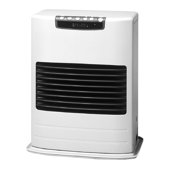
SECTION D: OPERATING CONTROLS AND PART NAMES Ciraulation air filter Rear cover (upper) Rear cover (right) 13. Room temperature sensor Fuel inlet 14. Power supply cord 3. Timer button 1st TIMER OM-22 10. Temperature lamp 11. AM lamp 12. PM lamp Control panel Front panel Louver... - Page 6 ON/OFF switch: Main switch turns heater on and off. When switched on, heater begins operation and combustion starts after preheat period. Power Saver button: The button turns Power Saver operation mode on and off. Timer button: The button turns Timer operation mode on and off. Temp./ Timer/Clock set: Temp./Timer/Clock set modes can be set by pressing UP/HOUR or DOWN/MIN buttons.
- Page 7 REF # PART # PART NAME 2 0 4 7 9 8 2 7 Front panel (Type A) 2 0 4 7 9 8 2 8 Front panel (Type B) 2 0 4 7 9 8 6 0 Top plate assembly 2 0 4 7 9 7 7 6 Indicator lamp circuit 2 0 4 7 8 3 7 3...
-
Page 8: Section E
SECTION E: OPERATION Open the Valve(s) Open the valve(s) of the external fuel tank. Start the Fuel flow If using heater for the first time, press the red reset button in order to send fuel to the fuel sump and release. Note: Make sure there is no fuel leakage from the fuel line or joints. - Page 9 Turn Heater ON A. Press ON/OFF switch to “ON” position. The current room temperature and the set temperature will be shown on the digital indicator. POWER lamp will start to flash and then blower motor and ignition will start. This lamp will continue to flash during the preheating time. B.
- Page 10 POWER SAVER OPERATION The Power Saver mode reduces the frequency of ignition actions, to save electric consumption. Press the POWER SAVER button “ON” to start the operation of the “POWER SAVER”. When the room temperature exceeds the selected setting by approximately 10°F, the heater will automatical- ly shut off.
-
Page 11: Turning Heater Off
Setting 1st Timer/2nd Timer: 1. Make sure the clock is set. If not, press the hour and minute button until the correct time is indicated. 2. Press 1st Timer button. Use the up and down arrows to set the time at which you want the room to return to normal temperature. -
Page 12: Section F
SECTION F: ROUTINE MAINTENANCE CAUTION: Be sure to unplug heater before performing any checks or cleaning. CAUTION: Allow heater to cool completely before cleaning or maintenance. FOR OPTIMUM HEATER PERFORMANCE, THE PARTS SHOWN BELOW SHOULD BE CLEANED REGULARLY: Control panel Front panel Louver Drip tray... - Page 13 Clean Fuel Strainer (ONCE A MONTH) The strainer of the fuel sump should be cleaned once a month and before storing heater at the end of each season. (a) Close the valve(s) of the separate fuel tank. (b) To catch the fuel which will drain out, set the oil catch below the strainer cover, with a small container under it.
-
Page 14: Section G
SECTION G: TROUBLESHOOTING NOTE BEFORE REQUESTING REPAIR AND SERVICES The following symptoms are normal during operation of the heater. CONDITION White smoke or smell at initial use after pur- chase. Flames flashing for a few minutes after igni- tion. Occasionally makes “cracking” noise when heater is ignited or extinguished. -
Page 15: Section H
SECTION H: LONG TERM STORAGE At the close of each heating season, or when you do not plan to use your heater for an extended period, the following procedures are recommended. As the end of the season approaches, calculate your fuel purchases so that you can use up all the fuel you have on hand. -
Page 16: Section I
SECTION I: INSTALLATION TOOLS NEEDED FOR INSTALLATION Tool Phillips Head Screwdriver Electric Drill Hole Saw, 2- to 3“ diameter STANDARD INSTALLATION PARTS The following standard installation parts are enclosed with heater. For alternate installation methods, you may need to purchase additional accessories which are available from your TOYOSTOVE dealer. See ”Accessory Parts“. - Page 17 Flue Pipe (1) (PART #20479891) Exhaust Air Cap (1) (PART #20479845) Intake Air Cap (1) (PART #20474949) 6-5/16¨ Bent Joint (1) (PART #20479584) Oil Catch (1) (PART #20474925) 10-5/8¨ Insulating Cloth Cover (1) (PART #20474955) 15-3/4¨ Inlet Hose (1) (PART #20474951) L-Shaped Hose (2) (PART #20474975) Hose Band (4) (PART #20474977) Spacer (1) (PART #20478967)
-
Page 18: Accessary Parts
The following accessory parts are available for use of the OM-22. After giving careful consideration to your desired heater and flue pipe locations and fueling system, consult your TOYOSTOVE dealer to purchase the necessary accessory parts. Important: Use only genuine TOYOSTOVE parts for your heater. Use of unauthorized generic or other brand parts can severely reduce performance and safety, and will invalidate factory warranty. - Page 19 Extension Pipe Kit (L) Max. 39- ~ Min. 22- inch (# 20479853) inch (# 20479872) 80 inch (# 20474951) 40 inch (# 20474955) Name of Part Q’ty Adjustable Exhaust Pipe Max. 39- ~ 22- Exhaust Extension Pipe (long, 39- inch) Intake Pipe (80 inch) Insulating cloth cover (40 inch)
- Page 20 Extension Pipe Kit (M) PART #20479897 Max. 39- ~ Min. 22- inch (# 20479861) (# 20479853) Pipe Support Hardware 40 inch Pipe Holder (2 pcs.) (# 20474951) Pipe Holder Support (1 pc.) 40 inch Screw (# 20474955) (1 pc.) Figure 2 Name of Part Q’ty Adjustable Exhaust Pipe...
-
Page 21: Safety Tips For Installation
Follow the safety tips below when planning the installation of your OM-22. Intake and exhaust flue pipe openings must be fully exposed to outside air. Do not vent into garage, basement under the floor, or into any enclosed area. Do not install flue pipe in close proximity to other objects or materials (See page 22). -
Page 22: Installation Of Heater And Flue Pipe
INSTALLATION OF HEATER AND FLUE PIPE IMPORTANT: Check and comply with all state and local codes that may apply to vented heaters before beginning installation. NOTE: This heater is designed to be used no more than 3000 FT. above sea level. ASK your local dealer for using at altitudes higher than 3000 FT. - Page 23 For standard installation, use the template enclosed with the heater to position the hole for the flue pipe. Tack or tape template to the wall at the desired position (See Fig. 4) NOTE: Heater should be installed on a sturdy floor that is level and flat. NOTE: The template can be adjusted for use of non-standard installations such as the use of extension pipe kits.
- Page 24 Install the inner flue pipe. For wall thickness 5- ” to 9” From inside the room, insert the inner flue pipe through the hole. Make sure the arrow on the inner flue pipe is pointing up. Secure the inner flue pipe to the wall with the three wood screws. (See Fig.
- Page 25 Insert the bent joint to the exhaust mouth of the standard flue pipe. Cut the inlet hose for desired length if necessary. Attach the L-shaped hose to each end of the inlet hose and attach the L-shaped hose to the intake mouth of the standard flue pipe.
- Page 26 Secure the L-shaped hose to the intake inlet mouth with the hose band. Secure the bent joint to the standard flue pipe with the pipe holder (If the extension pipe is used, also attach the pipe holder to the connection of the bent joint and the extension pipe). Secure the bent joint (or the extension pipe) to the exhaust outlet mouth by sliding the pipe stopper into the exhaust mouth bracket (See Fig.
- Page 27 A room temperature sensor is provided with approximately 8 feet long extension wire. It is located on the rear of the cabinet. Make sure that the extension wire is not touching the exhaust pipe. The room temperature sensor can be installed either with the self adhesive tape on the back or with a wood screw provided with the sensor depending on the type of surface chosen for installation.
-
Page 28: Permanent Wiring Installation
PERMANENT WIRING INSTALLATION WARNING: MAKE SURE POWER SUPPLY CORD IS DISCONNECTED TO AVOID ANY ELECTRIC SHOCK BEFORE SERVICING. ELECTRIC SHOCK MAY CAUSE SERIOUS INJURY. INSTALLATION SHOULD BE CONDUCTED BY A LICENSED ELECTRICIAN. Step 1. Disconnect power supply cord from power source. Remove two (2) screws on the front panel of the heater. -
Page 29: Section J
SECTION J: FUELING WARNING: Use ASTM D3699 1-K Kerosene, ASTM D396 No.1 or No.2 Fuel Oil. NEVER USE GASOLINE. Use of gasoline can lead to uncontrollable flames resulting in destructive fire. ¡Large Capacity External Tank Tank must be purchased separately and installed by a qualified fuel supply technician. NOTE: External tank installation must comply with National Fire Protection Association Code NFPA 31 or locally applicable codes. - Page 30 Oil guide OIL GUIDE INSTALLATION When the fuel piping is installed, hook one fuel guide on the fuel pipe, then fit the other oil guide on the drip tray so that it pushes down from above.
-
Page 31: Limited Warranty
WHO IS COVERED : The original purchaser at retail. WHAT WE WILL DO : TOYOTOMI will either repair or replace, at its option, all defective parts free of charge that are covered by this limited warranty on a carry-in basis, to your nearest authorized dealer or distributor of TOYOTOMI.
Need help?
Do you have a question about the OM-22 Type C and is the answer not in the manual?
Questions and answers