Table of Contents
Advertisement
Quick Links
Centronic EasyControl
EC545A-II
Assembly and Operating Instructions
en
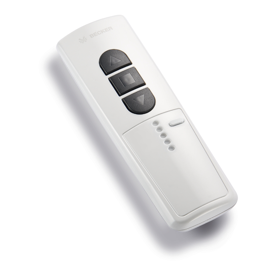
5-channel hand-held transmitter
Important information for:
• Fitters / • Electricians / • Users
Please forward accordingly!
These instructions must be kept safe for future reference.
4034 630 196 0 14/07/2022
Becker-Antriebe GmbH
Friedrich-Ebert-Straße 2-4
35764 Sinn/Germany
www.becker-antriebe.com
Advertisement
Table of Contents

Related Manuals for Becker Centronic EasyControl EC545A-II


Summary of Contents for Becker Centronic EasyControl EC545A-II
- Page 1 Assembly and Operating Instructions 5-channel hand-held transmitter Important information for: • Fitters / • Electricians / • Users Please forward accordingly! These instructions must be kept safe for future reference. 4034 630 196 0 14/07/2022 Becker-Antriebe GmbH Friedrich-Ebert-Straße 2-4 35764 Sinn/Germany www.becker-antriebe.com...
-
Page 2: Table Of Contents
Table of contents General information ................. 3 Warranty .................... 3 Safety instructions ................... 4 Intended use ................... 5 Explanation of displays and buttons ............ 6 Explanation of functions ................ 7 Programming the transmitter .............. 8 Installing the wall bracket................ 9 Changing batteries................... -
Page 3: General Information
General information With this transmitter you are able to control up to 5 receivers via assigned channels individually or all at the same time. This device is exceptionally easy to use. Please observe these Assembly and Operating Instructions when installing and setting up the equipment. Explanation of pictograms CAUTION indicates a hazardous situation CAUTION... -
Page 4: Safety Instructions
Safety instructions General information • Please keep the instruction manual safe! • Only use in dry rooms. • Only use unmodified original parts from the control unit manufacturer. • Keep children away from control units. • Observe all pertinent country-specific regulations. •... -
Page 5: Intended Use
Intended use The transmitter described in these instructions must only be used for operat- ing Centronic-compatible radio drives and radio control units. • Please note that radio-controlled systems may not be used in areas with a high risk of interference (e.g. hospitals, airports). •... -
Page 6: Explanation Of Displays And Buttons
Explanation of displays and buttons UP button STOP button DOWN button Channel selection button Channel indicator lamps Programming button Labelling field Type plate 6 - en... -
Page 7: Explanation Of Functions
Explanation of functions Channel The channel of a transmitter can be programmed into one or more receivers. One receiver is operated through an individual command, several receivers through a group command. Central command If all the channels of the transmitter are selected, it is possible to operate all of the assigned receivers/groups simultaneously. -
Page 8: Programming The Transmitter
Programming the transmitter 1) Programming the master transmitter a) Readying the receiver for programming The master transmitter refers to the very first transmitter programmed in a receiver. In contrast to subsequently pro- grammed transmitters, the master transmitter enables, among other things, the setting of limit positions and the programming or deleting of further transmitters. -
Page 9: Installing The Wall Bracket
Installing the wall bracket • Before installation in the de- sired installation position, Wall bracket check that the transmitter and receiver are functioning prop- erly. Wall bracket Unlocking mechanism mounting • Fix the bracket to the wall with plate the two screws enclosed. Changing batteries You will find the appropriate battery type in the "Technical data"... -
Page 10: Technical Data
Technical data Rated voltage 3 V DC Battery type CR 2430 Degree of protection IP 20 Permissible ambient temperature -10 °C to +55 °C Maximum emitted transmission output ≤ 3 mW Radio frequency 915.3 MHz The maximum transmitter range on and in the building is up to 15 m, and up to 150 m in the open.
Need help?
Do you have a question about the Centronic EasyControl EC545A-II and is the answer not in the manual?
Questions and answers