Table of Contents
Advertisement
Quick Links
B-Tronic EasyControl
EC5401B
Assembly and Operating Instructions
en
Wall/hand-held transmitter, 1-channel,
bidirectional
Important information for:
• Fitters / • Electricians / • Users
Please forward accordingly!
These instructions must be kept safe for future reference.
4035 630 003 0f 05/12/2018
Becker-Antriebe GmbH
Friedrich-Ebert-Straße 2-4
35764 Sinn/Germany
www.becker-antriebe.com
Advertisement
Table of Contents

Related Manuals for Becker B-Tronic EasyControl EC5401B


Summary of Contents for Becker B-Tronic EasyControl EC5401B
- Page 1 Assembly and Operating Instructions Wall/hand-held transmitter, 1-channel, bidirectional Important information for: • Fitters / • Electricians / • Users Please forward accordingly! These instructions must be kept safe for future reference. 4035 630 003 0f 05/12/2018 Becker-Antriebe GmbH Friedrich-Ebert-Straße 2-4 35764 Sinn/Germany www.becker-antriebe.com...
-
Page 2: Table Of Contents
Table of contents General .................... 3 Warranty .................... 3 Safety instructions ................... 4 Intended use ................... 5 Explanation of displays and buttons ............ 6 Normal/master mode ................ 8 Programming the first transmitter.............. 9 Querying/Changing the receiver mode ............. 10 Programming more transmitters .............. 12 Deleting transmitters................ 14 Changing the direction of rotation of B-Tronic products ...... 16 Setting the limit positions of B-Tronic tubular drives........ 17... -
Page 3: General
General You can operate drives and control units with bidirectional KNX radio with this transmitter. This device is exceptionally easy to use. Please observe these Assembly and Operating Instructions when installing and setting up the equipment. Explanation of pictograms CAUTION indicates a hazardous situation CAUTION which, if not avoided, could result in in- jury. -
Page 4: Safety Instructions
Safety instructions General information • Please keep the instructions safe! • Only use in dry rooms. • Only use unmodified original parts from the control unit manufacturer. • Keep children away from control units. • Observe all pertinent country-specific regulations. •... -
Page 5: Intended Use
Intended use The transmitter described in these instructions may only be used for operating suitable drives and control units with bidirectional KNX radio. You can operate either one group or a number of groups of devices with this transmitter. • Please note that radio-controlled systems may not be used in areas with a high risk of interference (e.g. -
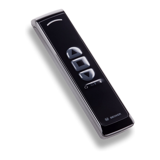
Page 6: Explanation Of Displays And Buttons
Explanation of displays and buttons 1 Wall bracket receptacle 7 Changeover switch 8 DOWN button 2 Master button 9 STOP button 3 Type plate 10 UP button 4 Batteries 5 Battery compartment cover 11 Status LED 6 Programming button (behind the logo) - Page 7 Functional overview of the control buttons UP ( ), STOP ( ), DOWN ( ) Roller shutter <1s >1s Screen <1s >1s Blind <1s >1s Roof window <1s >1s ON/OFF <1s >1s Pulse <1s >1s If present. With a STOP command, the STEP is always made in the UP direction...
-
Page 8: Normal/Master Mode
Normal/master mode The transmitter can be operated in two modes: • Normal mode (normal operation) The commands that are issued apply to all the receivers of a channel. • Master mode (Setting mode for all B‑Tronic products) The commands issued apply exclusively to one selected receiver of a channel. The normal mode is set at the factory. -
Page 9: Programming The First Transmitter
Programming the first transmitter The receiver mode must always be set appropriately for the receiver. Roller shutter/venetian blind is the factory setting. Putting the receiver into programming mode Follow the Assembly and Operating Instructions for the re- ceiver. • Switch off the power supply to the receiver for 5 seconds, then switch it back on •... -
Page 10: Querying/Changing The Receiver Mode
Querying/Changing the receiver mode The receiver mode must always be set appropriately for the receiver. Roller shutter/venetian blind is the factory setting. Querying the current receiver mode There are different receiver modes. The receiver mode must always be set ap- propriately for the receiver (e.g. - Page 11 Changing to the desired receiver mode The current receiver mode is first indicated through the dis- play code. Briefly press the programming button, and then the changeover button for 5 seconds. Flashes Receiver mode roller shutter yellow once Flashes Receiver mode dimmer yellow twice Flashes...
-
Page 12: Programming More Transmitters
Programming more transmitters The receiver mode must always be set appropriately for the receiver. Roller shutter/venetian blind is the factory setting. Programming more B-Tronic transmitters in the B- Tronic receiver Put the receiver into programming mode in one of the three possible ways. Please make sure that only one receiver is in programming mode at any time. - Page 13 Putting the B-Tronic receiver into program- ming mode with the radio switch Switch the radio switch to the inside position. If the radio switch is already in this position, switch it to the outside and back to the inside position. ►...
-
Page 14: Deleting Transmitters
Deleting transmitters Deleting from B-Tronic receivers with two B-Tronic transmitters Put a programmed transmitter, other than the one that is to be de- leted, into master mode. Select the device by pressing the button until the desired device confirms. All the following settings will then only be executed for this device. While the transmitter is in master mode, the sym- bols on the changeover button flash green once per second. - Page 15 Deleting from B-Tronic receivers with one B-Tronic transmitter The last or only transmitter in a receiver can be deleted using the following deletion sequence. To program new transmit- ters, the receiver must again be put into programming mode. Put the transmitter into master mode. Select the device by pressing the button until the desired device confirms.
-
Page 16: Changing The Direction Of Rotation Of B-Tronic Products
Deleting a B-Tronic transmitter from a KNX RF compatible receiver from another manufacturer Please find the appropriate description in the instructions for the receiver or on our website. Changing the direction of rotation of B- Tronic products Check the direction of rotation before setting the limit positions. The shading solution must move in the correct direction when the UP or DOWN buttons are pressed. -
Page 17: Setting The Limit Positions Of B-Tronic Tubular Drives
Setting the limit positions of B-Tronic tubular drives Upper stop to lower stop Put the transmitter into master mode. Select the tubular drive by pressing the button until the tubular drive con- firms. All the following settings will then only be executed for this device. Open to the permanent upper stop. -
Page 18: Upper Point To Lower Point
Upper point to lower point Put the transmitter into master mode. Select the tubular drive by pressing the button until the tubular drive con- firms. All the following settings will then only be executed for this device. There is no shading solution length adjustment with this limit position setting. -
Page 19: Upper Stop To Lower Point
Upper stop to lower point Put the transmitter into master mode. Select the tubular drive by pressing the button until the tubular drive con- firms. All the following settings will then only be executed for this device. Open to the permanent upper stop. ▻... -
Page 20: Deleting The Limit Positions Of B-Tronic Tubular Drives
Deleting the limit positions of B-Tronic tubular drives Attention When one or both of the limit positions are deleted, all the other set functions (e.g. intermediate position) are deleted as well. Once set, the limit positions can only be deleted using mas- ter mode. -
Page 21: Performing The Programming Run On B-Tronic Radio Receivers
Deleting both limit positions Put the transmitter into master mode. Select the tubular drive by pressing the button until the tubular drive con- firms. All the following settings will then only be executed for this device. Open/close the shading solution to a point between the limit positions. -
Page 22: Deleting The Programming Run On B-Tronic Radio Receivers
Press the programming button and, within 1 second, also press the DOWN button and hold the two buttons down. ▻ The receiver confirms. ► The programming run is completed. Deleting the programming run on B-Tronic radio receivers Put the transmitter into master mode. Select the receiver by pressing the button until the required receiver con- firms. -
Page 23: Intermediate Positions/Tilt Positions
Intermediate positions/tilt positions The intermediate positions or tilt positions are freely select- able positions for the shading solution or blind between the two limit positions. Each travel button can be assigned one intermediate position/tilt position. Both limit positions must be set before an intermediate position is set. When both or individual limit positions are deleted, both in- termediate positions/tilt positions are deleted as well. - Page 24 Travelling to the desired intermediate position/tilt position Press the travel button for the desired intermedi- ate position/tilt position twice within one second. ► The shading solution runs to the intermedi- ate position/tilt position assigned to the travel button. Lights up Action successful with all receivers (green) or not green / successful with at least one receiver (red).
-
Page 25: Memory Function
Memory function Every B-Tronic radio receiver for roller shutter and blind installations can save switching times for UP and DOWN movement. In the " " operating mode, this movement is repeated every 24 hours. It does not matter what position the / changeover button is in when pro- gramming the switching time. -
Page 26: Upper Anti-Freeze Mechanism
Deleting the run times When deleting, both run times are always deleted. To delete the UP and DOWN run time, press the STOP button for 10 seconds. The receiver confirms. The run times are now deleted. Upper anti-freeze mechanism The upper anti-freeze mechanism (if present in the receiver) helps to prevent the roller shutter from freezing in the upper limit position, as the roller shutter stops just before the upper stop. -
Page 27: Activating/Deactivating Upper Anti-Freeze Mechanism
Activating/Deactivating upper anti-freeze mechanism Put the transmitter into master mode. Select the receiver by pressing the button until the desired receiver con- firms. All the following settings will then only be executed for this device. Open the shading solution to the upper limit position. Then re-press the programming button and also the STOP and UP buttons for approx. -
Page 28: Activating/Deactivating Repeater Mode
Open the shading solution to the upper limit posi- tion. Then press the teaching button and also the STOP and UP buttons for approximately 5 seconds. ▻ The receiver confirms. Activating/deactivating repeater mode Put the transmitter into master mode. Select the receiver by pressing the button until the desired receiver con- firms. -
Page 29: Reset The Transmitter To The Factory Setting
Reset the transmitter to the factory setting Attention If the transmitter is reset to factory settings, master mode will no longer give you access to the receiver or receivers in which the transmitter has been programmed. Please only make this setting when the batteries are new. Open the cover of the battery compartment. -
Page 30: Clean-Up Function For B-Tronic Products
Clean-up function for B-Tronic products All receivers that are programmed and no longer present can be cleared with the clean-up function. The clean-up function is always applied to the selected chan- nel. The switching commands sequence must be carried out in quick succession. -
Page 31: Changing Batteries
Changing batteries You will find the appropriate battery type in the "Technical data" chapter. Flashes If the status LED gives slow yellow flashes while yellow the button is being pressed, the batteries are al- most empty, and must be exchanged as soon as possible. -
Page 32: Wall Bracket
Wall bracket Check that the transmitter and receiver are working properly before mounting in the desired position. Fasten the bracket to the wall using the two enclosed screws. Now push the screw covers into the screw holes. Cleaning Only clean the device with a suitable cloth. Do not use aggressive cleaning agents that may damage the surface. -
Page 33: Technical Data
Technical data Rated Voltage 3 V DC Battery type LR 03 (AAA) Degree of protection IP 20 Permissible ambient temperature -10 to +55 °C Maximum emitted transmission output ≤ 25 mW Radio frequency 868.3 MHz Max. number of receivers The maximum transmitter range on and in the building is up to 25 m, and up to 350 m in the open. -
Page 34: Simplified Eu Declaration Of Conformity
Function cannot be set. Check the functionality in the receiver. Simplified EU declaration of conformity Becker-Antriebe GmbH hereby declares that this radio control system com- plies with Directive 2014/53/EU. The full text of the EU declaration of conformity is available at the following web address: www.becker-antriebe.com/ce...
Need help?
Do you have a question about the B-Tronic EasyControl EC5401B and is the answer not in the manual?
Questions and answers