Table of Contents
Advertisement
B-Tronic EasyControl
EC5415B
Assembly and Operating Instructions
en
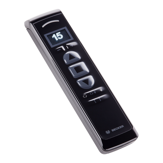
Wall/hand-held transmitter, 15-channel,
bidirectional
Important information for:
• Fitters / • Electricians / • Users
Please forward accordingly!
These instructions must be kept safe for future reference.
Becker-Antriebe GmbH
Friedrich-Ebert-Straße 2-4
35764 Sinn/Germany
www.becker-antriebe.com
Advertisement
Table of Contents

Related Manuals for Becker B-Tronic EasyControl EC5415B


Summary of Contents for Becker B-Tronic EasyControl EC5415B
- Page 1 B-Tronic EasyControl EC5415B Assembly and Operating Instructions Wall/hand-held transmitter, 15-channel, bidirectional Important information for: • Fitters / • Electricians / • Users Please forward accordingly! These instructions must be kept safe for future reference. Becker-Antriebe GmbH Friedrich-Ebert-Straße 2-4 35764 Sinn/Germany www.becker-antriebe.com...
-
Page 2: Table Of Contents
Table of contents General .................... 3 Warranty .................... 3 Safety instructions ................... 4 Intended use ................... 5 Explanation of displays and buttons ............ 6 Normal/master mode ................ 8 Programming the first transmitter.............. 8 Programming more transmitters .............. 11 Deleting transmitters................ 13 Setting the limit positions of B-Tronic tubular drives........ 15 Changing the direction of rotation ............ 15 Upper stop to lower stop .............. 16 Upper point to lower point .............. 16... -
Page 3: General
General You can operate drives and control units with bidirectional KNX radio with this transmitter. This device is exceptionally easy to use. Please observe these Assembly and Operating Instructions when installing and setting up the equipment. Explanation of pictograms CAUTION indicates a hazardous situation CAUTION which, if not avoided, could result in in- jury. -
Page 4: Safety Instructions
Safety instructions General information • Please keep the instructions safe! • Only use in dry rooms. • Only use unmodified original parts from the control unit manufacturer. • Keep children away from control units. • Observe all pertinent country-specific regulations. •... -
Page 5: Intended Use
Intended use The transmitter described in these instructions may only be used for operating suitable drives and control units with bidirectional KNX radio. You can operate either one group or a number of groups of devices with this transmitter. • Please note that radio-controlled systems may not be used in areas with a high risk of interference (e.g. -
Page 6: Explanation Of Displays And Buttons
Explanation of displays and buttons 1 Wall bracket receptacle 8 Changeover button 9 DOWN button 2 Master button 10 STOP button 3 Type plate 11 UP button 4 Batteries 12 Channel selection button 5 Battery compartment cover 6 Programming button (behind 13 Display the logo) -
Page 7: Explanation Of Symbols
Explanation of display 1 Scenario selection 2 Battery status 3 Selected channel 4 Application Explanation of symbols Symbol Explanation Repeater mode active Repeater mode inactive Roller shutters Dimmer Switch Blind Screen Roof window Central scene The displayed channel is not linked into the selected scene The displayed channel is linked into the selected scene The displayed scenario is presently being edited... -
Page 8: Normal/Master Mode
Fault indication Normal/master mode The transmitter can be operated in two modes: • Normal mode (normal operation) The commands that are issued apply to all the receivers of a channel. • Master mode (Setting mode for all B‑Tronic products) The commands is- sued apply exclusively to one selected receiver of a channel. - Page 9 • Switch off the receiver power for 5 seconds, then switch it back on. • Operate the programming button or the radio switch on the receiver. The receiver is now in programming mode for 3 minutes. b) Programming transmitters Please make sure that only one receiver is in programming mode at any time.
- Page 10 Flashes Receiver mode venetian blind yellow four times Flashes Receiver mode screen yellow five times Flashes Receiver mode roof window yellow six times 3) Changing to the desired receiver mode The current receiver mode is first indicated through the dis- play code.
-
Page 11: Programming More Transmitters
Flashes Receiver mode roof window yellow six times Repeat this procedure until the desired receiver mode has been selected. Programming more transmitters Programming more B-Tronic transmitters in the B- Tronic receiver Ready the receiver for programming in one of the three possible ways. Please make sure that only one receiver is in programming mode at any time. - Page 12 Readying the B-Tronic receiver for program- ming with the radio switch Switch the radio switch to the inside position. If the radio switch is already in this position, switch it to the outside and back to the inside position. ► The tubular drive goes into the programming mode for 3 minutes Press the programming button for 3 seconds.
-
Page 13: Deleting Transmitters
Deleting transmitters Deleting from B-Tronic receivers with two B-Tronic transmitters Put a programmed transmitter, other than the one that is to be de- leted, into master mode. Select the device by pressing the button until the desired device confirms. All the following settings will then only be executed for this device. While the transmitter is in master mode, the sym- bols on the changeover button flash green once per second. - Page 14 Deleting from B-Tronic receivers with one B-Tronic transmitter The last or only transmitter in a receiver can be deleted using the following deletion sequence. To program new transmit- ters, the receiver must again be put into programming mode. Put the transmitter into master mode. Select the device by pressing the button until the desired device confirms.
-
Page 15: Setting The Limit Positions Of B-Tronic Tubular Drives
Deleting a B-Tronic transmitter from a KNX RF compatible receiver from another manufacturer Please find the appropriate description in the instructions for the receiver or on our website. Setting the limit positions of B-Tronic tubular drives Changing the direction of rotation Check the direction of rotation before setting the limit positions. -
Page 16: Upper Stop To Lower Stop
Upper stop to lower stop Put the transmitter into master mode. Select the tubular drive by pressing the button until the tubular drive con- firms. All the following settings will then only be executed for this device. Open to the permanent upper stop. ▻... -
Page 17: Upper Stop To Lower Point
Press the programming button and, within 1 second, also press the DOWN button and hold the two buttons down. ▻ The tubular drive makes a "click" sound to confirm. ► The limit positions are now set. Upper stop to lower point Put the transmitter into master mode. -
Page 18: Upper Point To Lower Stop
Upper point to lower stop Put the transmitter into master mode. Select the tubular drive by pressing the button until the tubular drive con- firms. All the following settings will then only be executed for this device. Open to the desired upper limit position. Press the programming button and, within 1 second, also press the UP button and hold the two buttons down. - Page 19 Open/close to the limit position to be deleted. Press the programming button and, within the next 1 second, press the STOP button at the same time and hold the two buttons down for 5 seconds. ▻ The tubular drive makes a "click-click" sound to confirm.
-
Page 20: Intermediate Positions I + Ii
Intermediate positions I + II The intermediate positions I + II are freely selectable posi- tions for the shading solution between the two limit posi- tions. Each travel button can be assigned one intermediate position. Both limit positions must be set before an interme- diate position is set. -
Page 21: Memory Function
Deleting the desired intermediate position Press the travel button for the desired intermedi- ate position twice within one second. ▻ The shading solution runs to the inter- mediate position assigned to the travel button. Press the STOP button and, within 3 seconds, also press the travel button assigned to the intermedi- ate position and hold the two buttons down. -
Page 22: Upper Anti-Freeze Mechanism
Programming the run times The tubular drive must be in the upper limit position to program the DOWN run time, and must be in the lower limit position for the UP run time. Wait for the time you wish the automatic drive command to be executed. At the desired time, press and hold the relevant direction button until the tubular drive briefly stops after approx. -
Page 23: Activating/Deactivating Upper Anti-Freeze Mechanism
Activating/Deactivating upper anti-freeze mechanism Put the transmitter into master mode. Select the tubular drive by pressing the button until the tubular drive con- firms. All the following settings will then only be executed for this device. Open the shading solution to the upper limit position. Then re-press the programming button and also the STOP and UP buttons for approx. -
Page 24: Activating/Deactivating Repeater Mode
Activating/deactivating the fly screen protection function Put the transmitter into master mode. Select the tubular drive by pressing the button until the tubular drive con- firms. All the following settings will then only be executed for this device. Open the shading solution to the upper limit posi- tion. -
Page 25: Reset The Transmitter To The Factory Setting
Repeater mode deactivated Reset the transmitter to the factory setting Attention If the transmitter is reset to factory settings, master mode will no longer give you access to the tubular drive or drives in which the transmitter has been programmed. Please only make this setting when the batteries are new. -
Page 26: Clean-Up Function For B-Tronic Products
Clean-up function for B-Tronic products All receivers that are programmed and no longer present can be cleared with the clean-up function. The clean-up function is always applied to the selected chan- nel. The switching commands sequence must be carried out in quick succession. - Page 27 Use the channel selection button to select the de- sired scenario. Press the scenario button in order to confirm scenario selection. indicator shows you the scen- ario that is selected and presently being edited. Select the channel on which the receiver that is to be added is located (in the example this is Chan- nel 5).
- Page 28 When you want to leave the scenario modification mode, press the changeover button. When you want to leave the scenario mode, press the changeover button. After 30 seconds in which a button is not operated, the control unit automat- ically switches into operating mode. Calling up a scenario Press the scenario button in order to enter scen- ario selection.
- Page 29 Stopping a scenario during execution Press the STOP button All the devices in the selected scenario re- main in the position or retain the switching status that they have at the moment when the stop command is received. Lights up Action completed successfully (green) or not suc- green / cessfully (red).
- Page 30 Deleting a scenario Press the scenario button in order to enter scen- ario selection. Use the channel selection button to select the scenario that is to be deleted. Press the programming button and the scenario button for 3 seconds in order to delay the desired scenario.
-
Page 31: Changing Batteries
Changing batteries You will find the appropriate battery type in the "Technical data" chapter. Flashes If the status LED gives slow yellow flashes while yellow the button is being pressed, the batteries are al- most empty, and must be exchanged as soon as possible. -
Page 32: Wall Bracket
Wall bracket Check that the transmitter and receiver are working properly before mounting in the desired position. Fasten the bracket to the wall using the two enclosed screws. Now push the screw covers into the screw holes. Cleaning Only clean the device with a suitable cloth. Do not use aggressive cleaning agents that may damage the surface. -
Page 33: Technical Data
Technical data Rated Voltage 3 V DC Battery type LR 03 (AAA) Degree of protection IP 20 Permissible ambient temperature -10 to +55 °C Radio frequency 868.3 MHz Max. number of receivers The maximum transmitter range on and in the building is up to 25 m, and up to 350 m in the open. - Page 34 Problem Remedy Status LED flashes red Check the path for an obstacle. for three seconds after operating one of , or buttons. Status LED lights up red Reduce the distance to the receiver. for three seconds Check the batteries Check the power supply at the receiver. after operating one of , or buttons.
-
Page 35: General Declaration Of Conformity
General Declaration of Conformity Becker-Antriebe GmbH declares that the B-Tronic EasyControl EC5415B device complies with the fundamental requirements and other relevant guidelines of Directive R&TTE 1999/5/EC. Intended for use in the following countries: EU, CH, NO, IS, LI Subject to technical changes without notice... - Page 36 4035 630 004 0c 21/04/2015 ...
Need help?
Do you have a question about the B-Tronic EasyControl EC5415B and is the answer not in the manual?
Questions and answers