Table of Contents
Advertisement
Quick Links
Service Manual
Crawler Crane
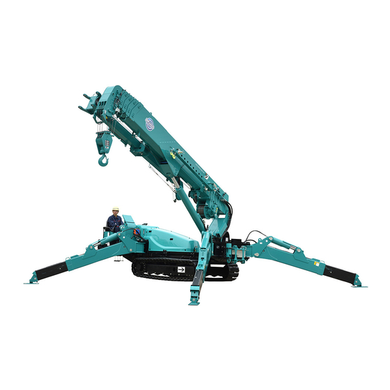
MC815C
Serial No. T0001 and up
Part numbers and parts list in the Service Manual are for use for
servicing such as disassembling and assembling.
The parts and part numbers are subject to change without prior notice
due to continuous machine improvement and modification. When
ordering parts, make sure to check the latest parts catalog (latest
information).
106E-SM1804-00
Advertisement
Chapters
Table of Contents
Troubleshooting

Related Manuals for Maeda MC815C


Summary of Contents for Maeda MC815C
- Page 1 106E-SM1804-00 Service Manual Crawler Crane MC815C Serial No. T0001 and up Part numbers and parts list in the Service Manual are for use for servicing such as disassembling and assembling. The parts and part numbers are subject to change without prior notice due to continuous machine improvement and modification.
-
Page 3: Table Of Contents
1.2 ENGINE MOUNT 1.3 PTO (POWER TAKE-OFF) 1.4 COOLING SYSTEM 1.5 FUEL LINE 1.6 FUEL TANK 2. POWER TRANSMISSION SCHEMATIC DIAGRAM 2-10 2.1 HYDRAULIC SYSTEM DIAGRAM (MC815C) 2-10 2.2 SWING CIRCLE 2-11 3. UNDERCARRIAGE AND FRAME 2-12 3.1 TRACK FRAME 2-12 3.2 IDLER CUSHION... - Page 4 Item Page 4. HYDRAULIC UNITS 2-22 4.1 HYDRAULIC UNITS LAYOUT DIAGRAM 2-22 4.1.1 HYDRAULIC CIRCUIT DIAGRAM 2-24 4.2 HYDRAULIC OIL TANK AND FILTER 2-26 4.3 HYDRAULIC PUMP 2-27 4.3.1 HYDRAULIC PUMP EXTERNAL VIEW 2-27 4.3.2 HYDRAULIC PUMP CONNECTION DESTINATIONS 2-28 4.3.3 HYDRAULIC PUMP SPECIFICATIONS 2-28 4.3.4 PUMP HYDRAULIC CIRCUIT DIAGRAM...
- Page 5 Item Page 4.13 DERRICK CYLINDER 2-47 4.13.1 DERRICK CYLINDER EXTERNAL VIEW 2-47 4.13.2 DERRICK CYLINDER CONNECTION DESTINATIONS 2-48 4.13.3 DERRICK CYLINDER SPECIFICATIONS 2-48 4.13.4 COUNTERBALANCE VALVE (IDENTIFICATION STAMP “D” FOR DERRICKING CYLINDER) 2-49 4.13.5 COUNTER-BALANCE VALVE OPERATING DIAGRAM 2-50 4.14 TELESCOPIC CYLINDER ASSEMBLY 2-51 4.14.1 TELESCOPIC CYLINDER EXTERNAL VIEW 2-51...
- Page 6 Item Page 8. ELECTRICAL UNITS 2-97 8.1 CABIN INTERIOR 2-97 8.1.1 NAME OF EACH CONTROL PART 2-97 8.1.2 OUTRIGGER OPERATION PANEL 2-98 8.1.3 LEFT CONTROL LEVER 2-98 8.1.4 RIGHT CONTROL LEVER 2-101 8.1.5 MONITOR 2-104 2-106 8.1.6 LIST OF ERROR CODES 2-111 8.1.7 CONSUMABLES DISPLAY 2-112...
- Page 7 Item Page REMOTE CONTROL 1. COMPONENTS OF THE TRANSMITTER 1.1 NAMES AND DESCRIPTION OF REMOTE CONTROL PARTS 1.1.1 TRANSMITTER AND RECEIVER 1.1.2 DESCRIPTION OF REMOTE CONTROLLER ACCESSORIES 2. HANDLING REMOTE CONTROLLER BATTERY 2.1 REPLACEMENT TIMING OF BATTERY 2.2 REPLACEMENT METHOD OF BATTERY 2.3 CHARGING METHOD OF BATTERY 3.
- Page 8 Item Page FLY JIB 1. NAME OF EACH SECTION OF FLY JIB 2. FLY JIB HYDRAULIC SYSTEM 2.1 SOLENOID OPERATED DIRECTIONAL CONTROL VALVE (JIB SWITCHING SOL) 2.2 HOSE REEL 2.3 DERRICKING CYLINDER (FOR FLY JIB) 2.4 TELESCOPING CYLINDER (FOR FLY JIB) 2.5 SELECTOR VALVE BLOCK (FLY JIB TELESCOPIC CYLINDER MOUNTED) 3.
- Page 9 Item Page DISASSEMBLING AND ASSEMBLING 1. DISMOUNTING AND MOUNTING THE BOOM ASSEMBLY 1.1 DISMOUNTING THE BOOM 1.2 MOUNTING THE BOOM 1.3 CONNECTION DIAGRAM FOR BOOM EQUIPMENT 2. DISASSEMBLING AND ASSEMBLING THE BOOM ASSEMBLY 2.1 DISASSEMBLING THE NO.1 BOOM 2.2 DISASSEMBLING THE NO.2 BOOM 2.3 DISASSEMBLING THE NO.3 BOOM 2.4 DISASSEMBLING THE NO.4 BOOM 2.5 DISASSEMBLING THE TELESCOPIC CYLINDER FROM THE NO.
- Page 10 This Page Intentionally Left Blank.
-
Page 11: Overview
OVERVIEW CONTENTS Item Page 1. EXTERNAL VIEW 2. DIMENSIONAL DRAWING OF OUTRIGGER WIDTH 3. PRINCIPAL SPECIFICATIONS LIST 4. COMPONENT MASS LIST 5. OIL AND WATER QUANTITIES LIST 6. RATED TOTAL LOAD CHART 7. WORKING RADIUS/LIFTING HEIGHT 1-21 8. WORKING RADIUS AND HOISTING HEIGHT (TRAVELLING WITH HOISTED LOAD) 1-22... -
Page 12: External View
1. EXTERNAL VIEW 1.1 STANDARD SPECIFICATIONS 1.2 SEARCHER HOOK SPECIFICATIONS... -
Page 13: Fly-Jib Specifications
1.3 FLY-JIB SPECIFICATIONS 2. DIMENSIONAL DRAWING OF OUTRIGGER WIDTH... -
Page 14: Principal Specifications List
3. PRINCIPAL SPECIFICATIONS LIST 3.1 STANDARD SPECIFICATIONS Equipment/Item MC815CWM Machine mass 9460 kg Overall length × width × 5900 mm × 1670 mm × 2490 mm height Weight and Distance between centre 2245 mm dimensions idler and sprocket Track gauge 1270 mm Width of crawler 400 mm... -
Page 15: Engine And Electric Motor Specifications
3.2 ENGINE AND ELECTRIC MOTOR SPECIFICATIONS Equipment/Item MC815CWME (machines with engine & electric motor) Machine mass 9700 kg Overall length × width × 5900 mm × 1670 mm × 2490 mm height Weight and Distance between centre 2245 mm dimensions idler and sprocket Track gauge 1270 mm... -
Page 16: Remote Control Specifications
3.3 REMOTE CONTROL SPECIFICATIONS Equipment/Item Remote control Radio frequency 2402-2480 MHz band Transmission output 100 mW Channel spacing 1 MHz Reachable range of radio waves 100 m or longer (under a good condition where there is no radio interference) Unique address Extracted and set from 1 million or more addresses at the time of shipment from factory Waterproof IP65... -
Page 17: Component Mass List
4. COMPONENT MASS LIST Unit: kg Item MC815CWM Engine assembly 332.2 • Engine (without coolant oil) • Engine accessories 79.8 • PTO assembly • Hydraulic pump 28.5 Oil cooler assembly Crane frame assembly 1302.5 Operator seat assembly (including seat) 45.0 •... -
Page 18: Oil And Water Quantities List
5. OIL AND WATER QUANTITIES LIST Use of lubricating oil should vary with changes in temperature. • A specified oil quantity is defined as a total quantity of oil including that for unit piping, and a replacement oil quantity is defined as a quantity of oil to be replaced at inspection and maintenance. •... -
Page 19: Falls
6.1 6 FALLS 【 6 FALL HOOK , OUTRIGGER MAXIMUM EXTENSION 】 In the following table, the numbers for the boom length for the following conditions. 5.52m boom → boom fully retracted (1)+(2) 8.99m boom → boom length over 5.52m, less than 8.99m (1)+(2)+(3) 12.46m boom →... - Page 20 【 6 FALL HOOK , OUTRIGGER MEDIUM EXTENSION 】 In the following table, the numbers for the boom length for the following conditions. 5.52m boom → boom fully retracted (1)+(2) 8.99m boom → boom length over 5.52m, less than 8.99m (1)+(2)+(3) 12.46m boom →...
- Page 21 【 6 FALL HOOK , OUTRIGGER MINIMUM EXTENSION 】 In the following table, the numbers for the boom length for the following conditions. 5.52m boom → boom fully retracted (1)+(2) 8.99m boom → boom length over 5.52m, less than 8.99m (1)+(2)+(3) 12.46m boom →...
-
Page 22: Falls
6.2 4 FALLS 【 4 FALL HOOK , OUTRIGGER MAXIMUM EXTENSION 】 In the following table, the numbers for the boom length for the following conditions. 5.52m boom → boom fully retracted (1)+(2) 8.99m boom → boom length over 5.52m, less than 8.99m (1)+(2)+(3) 12.46m boom →... - Page 23 【 4 FALL HOOK , OUTRIGGER MEDIUM EXTENSION 】 In the following table, the numbers for the boom length for the following conditions. 5.52m boom → boom fully retracted (1)+(2) 8.99m boom → boom length over 5.52m, less than 8.99m (1)+(2)+(3) 12.46m boom →...
- Page 24 【 4 FALL HOOK , OUTRIGGER MINIMUM EXTENSION 】 In the following table, the numbers for the boom length for the following conditions. 5.52m boom → boom fully retracted (1)+(2) 8.99m boom → boom length over 5.52m, less than 8.99m (1)+(2)+(3) 12.46m boom →...
-
Page 25: Falls
6.3 2 FALLS 【 2 FALL HOOK , OUTRIGGER MAXIMUM EXTENSION 】 In the following table, the numbers for the boom length for the following conditions. 5.52m boom → boom fully retracted (1)+(2) 8.99m boom → boom length over 5.52m, less than 8.99m (1)+(2)+(3) 12.46m boom →... - Page 26 【 2 FALL HOOK , OUTRIGGER MEDIUM EXTENSION 】 In the following table, the numbers for the boom length for the following conditions. 5.52m boom → boom fully retracted (1)+(2) 8.99m boom → boom length over 5.52m, less than 8.99m (1)+(2)+(3) 12.46m boom →...
- Page 27 【 2 FALL HOOK , OUTRIGGER MINIMUM EXTENSION 】 In the following table, the numbers for the boom length for the following conditions. 5.52m boom → boom fully retracted (1)+(2) 8.99m boom → boom length over 5.52m, less than 8.99m (1)+(2)+(3) 12.46m boom →...
-
Page 28: Single Fall
6.4 SINGLE FALL 【 SINGLE FALL HOOK , OUTRIGGER MAXIMUM EXTENSION 】 In the following table, the numbers for the boom length for the following conditions. 5.52m boom → boom fully retracted (1)+(2) 8.99m boom → boom length over 5.52m, less than 8.99m (1)+(2)+(3) 12.46m boom →... - Page 29 【 SINGLE FALL HOOK , OUTRIGGER MEDIUM EXTENSION 】 In the following table, the numbers for the boom length for the following conditions. 5.52m boom → boom fully retracted (1)+(2) 8.99m boom → boom length over 5.52m, less than 8.99m (1)+(2)+(3) 12.46m boom →...
- Page 30 【 SINGLE FALL HOOK , OUTRIGGER MINIMUM EXTENSION 】 In the following table, the numbers for the boom length for the following conditions. 5.52m boom → boom fully retracted (1)+(2) 8.99m boom → boom length over 5.52m, less than 8.99m (1)+(2)+(3) 12.46m boom →...
-
Page 31: Working Radius/Lifting Height
7. WORKING RADIUS/LIFTING HEIGHT 1-21... -
Page 32: Working Radius And Hoisting Height (Travelling With Hoisted Load)
8. WORKING RADIUS AND HOISTING HEIGHT (TRAVELLING WITH HOISTED LOAD) In cases where travelling with hoisted load cannot be avoided, follow the rules below to prevent the machine from overturning. 1. Do not travel on slopes, soft ground, or ground that is not flat. 2. -
Page 33: Structure And Maintenance Procedure
STRUCTURE AND MAINTENANCE PROCEDURE CONTENTS Item Page 1. ENGINE AND COOLING-RELATED COMPONENTS 2. POWER TRANSMISSION SCHEMATIC DIAGRAM 2-10 3. UNDERCARRIAGE AND FRAME 2-12 4. HYDRAULIC UNITS 2-22 5. WORK EQUIPMENT 2-86 6. ELECTRIC CIRCUIT DIAGRAMS (1/3 - 3/3) 2-91 7. ELECTRICAL EQUIPMENT CONNECTION DIAGRAM (1/2 - 2/2) 2-94 8. -
Page 34: Engine And Cooling-Related Components
1. ENGINE AND COOLING-RELATED COMPONENTS 1.1 ENGINE SPECIFICATIONS 106-2187500... - Page 35 Item Model 4TNV88C-NMB Vertical in-line water-cooled 4 stroke diesel engine Type (Direct injection type) No. of cylinders - cylinder inside diameter × 4 - 88 - 90 mm stroke Total displacement 2.189 L Rated output 30.5 KW / 2,500 rpm Maximum torque 135 Nm / Approx.
-
Page 36: Engine Mount
1.2 ENGINE MOUNT 106-1186900... -
Page 37: Pto (Power Take-Off)
1.3 PTO (Power Take-Off) 106-2179100... -
Page 38: Cooling System
1.4 COOLING SYSTEM 106-1186900... - Page 39 106-1186900...
-
Page 40: Fuel Line
1.5 FUEL LINE 106-2187400... -
Page 41: Fuel Tank
1.6 FUEL TANK 106-2186800 Specifications Tank capacity (L) -
Page 42: Power Transmission Schematic Diagram
2. POWER TRANSMISSION SCHEMATIC DIAGRAM 2.1 HYDRAULIC SYSTEM DIAGRAM (MC815C) 2-10... -
Page 43: Swing Circle
2.2 SWING CIRCLE 106-1188300 Slewing reducer specifications Slewing bearing specifications Reduction gear ratio 1/25 Reduction gear ratio 87/13 = 6.7 Slewing reduction ratio 167.3 Injected grease Alvania EP2 (Showa Shell) Slewing speed (rpm) Quantity of injected grease (cc) Greasing swing circle Use a grease gun to inject grease through the grease plugs marked with arrows (7) in the right-hand figure. -
Page 44: Undercarriage And Frame
3. UNDERCARRIAGE AND FRAME 3.1 TRACK FRAME 106-1189300 2-12... - Page 45 2-13...
-
Page 46: Idler Cushion
3.2 IDLER CUSHION S106W3556000 Specifications Item Reference values L: Grease application No.2 lithium grease P: Quantity of grease (cc) Spring mounting length (mm) Mounting load (kgf) 5323 Spring free length (mm) 2-14... -
Page 47: Idler
3.3 IDLER S106W3555000 Specifications Item Reference values Allowable limit Oil type 85W-90 Oil quantity (cc) Outer diameter (mm) Tread outside diameter (mm) Tread width (mm) 2-15... -
Page 48: Track Roller
3.4 TRACK ROLLER S106W3560000 Specifications Item Reference values Allowable limit Oil type 85W-90 Oil quantity (cc) Outer diameter (mm) Tread outside diameter (mm) 2-16... -
Page 49: Carrier Roller
3.5 CARRIER ROLLER S106W3559000 Specifications Item Reference values Allowable limit Oil type 85W-90 Oil quantity (cc) Tread outside diameter (mm) Tread width (mm) 2-17... -
Page 50: Sprocket
3.6 SPROCKET S106W3557000 Specifications Item Reference values Allowable limit No. of teeth 424 416 Tooth tip diameter (mm) 415.77 Pitch circle diameter (mm) 380.8 372 Tooth root diameter (mm) 2-18... -
Page 51: Track Shoe
3.7 TRACK SHOE S106W3558000-1/2 Specifications Number of links 43 (on one side) 3.8 SHOE PLATE S106W3558000-2/2 2-19... -
Page 52: Adjusting Rubber Track Tension
3.9 ADJUSTING RUBBER TRACK TENSION [1] Inspection/adjustment of rubber track tension The pins and bushings around the footage of the Machine shows varied states of abrasion depending on the working conditions and soil quality. Check the tension of rubber track at any time to maintain the standard tension. Conduct the inspection and adjustment on a flat and solid ground. - Page 53 [Loosening the tension] Discharging grease without using the following procedure is extremely dangerous. If the rubber track is not loosened, ask us or our sales service agency for repair. Slowly loosen the plug (1) to discharge the grease. If the grease cannot be smoothly discharged, slightly move the Machine back and forth.
-
Page 54: Hydraulic Units
4. HYDRAULIC UNITS 4.1 HYDRAULIC UNITS LAYOUT DIAGRAM 2-22... - Page 55 2-23...
-
Page 56: Hydraulic Circuit Diagram
4.1.1 HYDRAULIC CIRCUIT DIAGRAM 2-24... - Page 57 This Page Intentionally Left Blank. 2-25...
-
Page 58: Hydraulic Oil Tank And Filter
4.2 HYDRAULIC OIL TANK AND FILTER 106-1186700 Specifications Consumption quantity in the tank Oil quantity in the tank (L) 2-26... -
Page 59: Hydraulic Pump
4.3 HYDRAULIC PUMP 4.3.1 HYDRAULIC PUMP EXTERNAL VIEW S1 port 106-2179000 2-27... -
Page 60: Hydraulic Pump Connection Destinations
4.3.2 HYDRAULIC PUMP CONNECTION DESTINATIONS Port Port destination Port size Note name Via shuttle manifold block G1/2 Left travel / Outrigger 1 / Outrigger 2 Left travel control valve P1 port (upper) Via shuttle manifold block G 1/2 Right travel / Outrigger 3 / Outrigger 4 Right travel control valve P1 port (lower) Twin solenoid valve P port G 1/4... -
Page 61: Shuttle Manifold Block
4.4 SHUTTLE MANIFOLD BLOCK S106J3645001 2-29... -
Page 62: Travel / Outrigger Control Valve
4.5 TRAVEL / OUTRIGGER CONTROL VALVE 4.5.1 TRAVEL / OUTRIGGER CONTROL VALVE EXTERNAL VIEW 106-2179000 2-30... -
Page 63: Travel / Outrigger Control Valve (Upper) Connection Destinations
4.5.2 TRAVEL / OUTRIGGER CONTROL VALVE (UPPER) CONNECTION DESTINATIONS Port name Port destination Port size Note Via shuttle manifold block G1/2 Main pump A1 port Port A Left travelling motor port A G3/8 Left: Forward Travelling left Port B Left travelling motor port B G3/8 Left: Backward Outrigger 1... -
Page 64: Hydraulic Specifications
4.5.4 HYDRAULIC SPECIFICATIONS 4.5.5 SOLENOID VALVE SPECIFICATIONS S106G3573000 Item No. High Rated pressure 24.5 pressure circuit (MPa) Tank circuit Service P1 / T1 flow rate (l/min) A / B 4.5.6 TRAVEL / OUTRIGGER CONTROL VALVE LAYOUT 2-32... -
Page 65: Travel / Outrigger Control Valve Circuit Diagram
4.5.7 TRAVEL / OUTRIGGER CONTROL VALVE CIRCUIT DIAGRAM 2-33... -
Page 66: Check Valve (Joint)
4.6 CHECK VALVE (JOINT) 106-2179000 2-34... -
Page 67: Crane Control Valve
4.7 CRANE CONTROL VALVE 4.7.1 CRANE CONTROL VALVE EXTERNAL VIEW 106-2179000 2-35... -
Page 68: Crane Control Valve Connection Destinations
4.7.2 CRANE CONTROL VALVE CONNECTION DESTINATIONS Port Valve name Port destination Port size Note name Derrick Derrick raising port via rotary joint A port G3/4 Derrick lowering port via rotary joint B port G3/4 Winch Winch raising port via rotary joint C port G3/4 Winch lowering port via rotary joint D port G3/4... -
Page 69: Crane Control Valve Layout
4.7.4 CRANE CONTROL VALVE LAYOUT 4.7.5 CRANE CONTROL VALVE SPECIFICATIONS Item No. S106G3572000 Rated High pressure circuit 20.6 pressure Tank circuit (MPa) Allowable High pressure circuit 34.3 pressure Tank circuit (MPa) Low pressure Low pressure circuit (MPa) Service flow rate A / B (l/min) 2-37... -
Page 70: Slewing Motor
4.8 SLEWING MOTOR 4.8.1 SLEWING MOTOR EXTERNAL VIEW S103H2171000 4.8.2 SLEWING MOTOR CONNECTION DESTINATIONS Port Port destination Port size Note name Crane control valve slewing A port G3/8 Slewing rightward Crane control valve slewing B port G3/8 Slewing leftward Hydraulic oil tank G1/4 4.8.3 SLEWING MOTOR SPECIFICATIONS Model... -
Page 71: Slewing Motor Internal Structure Diagram
4.8.4 SLEWING MOTOR INTERNAL STRUCTURE DIAGRAM Name Qty. Note Screw 5/16 UNF×22 Flange Dust seal Backup ring Oil seal O-ring Dimension: 44.1×2.6 Thrust bearing race Thrust bearing needle Output shaft Housing Drive O-ring Dimension: 92×2.5 Spacer plate Gerotor End cap Screw 5/16 UNF×73 Name plate... -
Page 72: Travelling Motor
4.9 TRAVELLING MOTOR 4.9.1 TRAVELLING MOTOR EXTERNAL VIEW S106H3567000 4.9.2 TRAVELLING MOTOR CONNECTION DESTINATIONS Port name Port destination Port size Note Left motor Travel / outrigger control valve left travel A port Forward travelling Right motor Travel / outrigger control valve right travel B port Backward travelling Left motor Travel / outrigger control valve left travel B port... -
Page 73: Travelling Speed Switching Valve Appearance / Specifications
4.10 TRAVELLING SPEED SWITCHING VALVE (JOINT WINCH BRAKE RELEASING VALVE / WINCH 2 SPEED SWITCHING VALVE) 4.10.1 TRAVELLING SPEED SWITCHING VALVE APPEARANCE / SPECIFICATIONS 349S55200000 Port destination Port size Travel control valve pressure detection port PF1/4 Left/right traveling motor PP port PF1/4 Drain PF1/4... -
Page 74: Winch Motor
4.11 WINCH MOTOR 4.11.1 WINCH MOTOR EXTERNAL VIEW S584A2234000 4.11.2 WINCH MOTOR CONNECTION DESTINATIONS Port Port destination Port size Note name Winch confluence valve B1 port Lifting Winch confluence valve A1 port Lowering Hydraulic oil tank PF1/2 Winch brake release valve C port PF1/4 Winch confluence valve C port PF1/4... -
Page 75: Winch Motor Specifications
4.11.3 WINCH MOTOR SPECIFICATIONS Specification value Service condition Reduction gear ratio 24.2 21.52 Maximum 4460 (455) 4000 (410) Running Reducer Output torque N•m (kgf•m) 3630 (370) Start Revolution speed, rpm 113/167 Maximum Stroke volume cm /rev 54.3 54.3/36.7 Maximum Pressure difference (continuous) 24.5 (250) 24.5 (250) Maximum... -
Page 76: Winch Venting
4.11.4 WINCH VENTING [1] Winch motor air venting Before loosening and tightening the air venting plug of winch motor, be sure to allow the hook block to touch the ground and set the work machine operation lever to "NEUTRAL" position. Otherwise, the internal pressure may force the plug or oil to jet out. -
Page 77: Rotary Joint
4.12 ROTARY JOINT 4.12.1 ROTARY JOINT EXTERNAL VIEW Rotary joint structure 106-2178500 2-45... -
Page 78: Rotary Joint Specifications
4.12.2 ROTARY JOINT SPECIFICATIONS Item No. S106J3568000 Port name A.B.C.D.E.F Maximum service pressure 25 MPa 5 MPa 0.5 MPa Withstand pressure 31 MPa 7 MPa 1.0 MPa Flow rate 90 l/min 15 l/min 15 l/min Revolution speed 1.5 min Temperature range of oil used -30 to 95ºC (instantaneously 100ºC) 4.12.3 ROTARY JOINT CONNECTION DESTINATIONS Rotary joint... -
Page 79: Derrick Cylinder
4.13 DERRICK CYLINDER 4.13.1 DERRICK CYLINDER EXTERNAL VIEW S106F356300 2-47... -
Page 80: Derrick Cylinder Connection Destinations
4.13.2 DERRICK CYLINDER CONNECTION DESTINATIONS Port Port destination Port size Note: name Rotary joint F port G3/8 Raising Rotary joint D port G3/8 Lowering Pressure sensor 1 bottom side port G3/8 Raising side Pressure sensor 2 rod side port G3/8 Lowering side 4.13.3 DERRICK CYLINDER SPECIFICATIONS 160 ×90-1420 st... -
Page 81: Counterbalance Valve (Identification Stamp "D" For Derricking Cylinder)
4.13.4 COUNTERBALANCE VALVE (IDENTIFICATION STAMP “D” FOR DERRICKING CYLINDER) 65200-01000 Specifications Max. working pressure 20.6 MPa (210 kgf/cm Withstand pressure 30.9 MPa (315 kgf/cm Max. flow rate 50 L/min Rated flow rate 40 L/min Allowable leak amount 0.05 cc/min or less (pressurizing 20.6 MPa [210 kgf/cm ] from B port) +0.3 Pilot pressure... -
Page 82: Counter-Balance Valve Operating Diagram
4.13.5 COUNTER-BALANCE VALVE OPERATING DIAGRAM 1. When neutral 2. When extending 3. When contracting 2-50... -
Page 83: Telescopic Cylinder Assembly
4.14 TELESCOPIC CYLINDER ASSEMBLY 4.14.1 TELESCOPIC CYLINDER EXTERNAL VIEW S106F3566001 2-51... -
Page 84: Telescopic Cylinder Connection Destinations
4.14.2 TELESCOPIC CYLINDER CONNECTION DESTINATIONS Port name Port destination Port size Note: Rotary joint E port G3/8 Extension Rotary joint C port G3/8 Contraction 4.14.3 TELESCOPIC CYLINDER SPECIFICATIONS Extension 20.6 MPa side Service pressure Retracting 20.6 MPa side 95 ×80 - 3470 st No. -
Page 85: Telescopic Cylinder Cross-Sectional Drawing
4.14.4 TELESCOPIC CYLINDER CROSS-SECTIONAL DRAWING 2-53... -
Page 86: Telescopic Cylinder Hydraulic System Diagram
4.14.5 TELESCOPIC CYLINDER HYDRAULIC SYSTEM DIAGRAM 2-54... -
Page 87: Sequence Valve
4.14.6 SEQUENCE VALVE 65100-01200 Specifications Rated flow rate 40 L/min Allowable leak amount 0.05 CC/min or less (pressurise 20.6 MPa [210 kgf/cm ] from port B) +0.3 Pilot pressure 1.18 MPa (12 kgf/cm ) at opening valve Check valve cracking pressure 2.45 MPa (25 kgf/cm Operating force 0.65 ×... -
Page 88: Mechanical Check Valve
4.14.7 MECHANICAL CHECK VALVE 65100-02200V Specifications Rated flow rate 50 L/min +0.3 Pilot pressure 1.18 MPa (12 kgf/cm ) at opening valve Pressure loss (B→A) 100 kgf/cm or less Cracking pressure 0.098 MPa (1 kgf/cm 2-56... -
Page 89: Counter Balance Valve (Identification Stamp "T" For Telescoping Cylinder)
4.14.8 COUNTER BALANCE VALVE (IDENTIFICATION STAMP “T” FOR TELESCOPING CYLINDER) 65200-00800 Specifications Max. working pressure 20.6 MPa (210 kgf/cm Withstand pressure 30.9 MPa (315 kgf/cm Max. flow rate 50 L/min Rated flow rate 40 L/min Allowable leak amount 0.05 cc/min or less (pressurizing 20.6 MPa [210 kgf/cm ] from B port) +0.3 Pilot pressure... -
Page 90: Outrigger Cylinder Assembly
4.15 OUTRIGGER CYLINDER ASSEMBLY 4.15.1 OUTRIGGER CYLINDER EXTERNAL VIEW S106F3570001 2-58... -
Page 91: Outrigger Cylinder Connection Destinations
4.15.2 OUTRIGGER CYLINDER CONNECTION DESTINATIONS Port Port destination Port size Note: name OR select valve C3 port G1/4 Extension OR select valve C2 port G1/4 Contraction 4.15.3 OUTRIGGER CYLINDER SPECIFICATIONS 140 ×80 - 302 st Size Extension 20.6 MPa side Service pressure Retracting 20.6 MPa... -
Page 92: Double Pilot Check Valve
4.15.4 DOUBLE PILOT CHECK VALVE 103S92800000 (65000-06400) Specifications Rated pressure 20.6 MPa (210 kgf/ cm Test pressure 41.2 MPa (420 kgf/ cm Max. flow rate 10 L/min Allowable leak amount 0.05 cc/min (pressurizing 17.2 MPa [175 kgf/ cm ] from A2 and B2 ports) Check cracking pressure 0.49 MPa (5 kgf/ cm Pilot area ratio... -
Page 93: Slide Cylinder Assembly
4.16 SLIDE CYLINDER ASSEMBLY 4.16.1 SLIDE CYLINDER EXTERNAL VIEW S106F3571001 2-61... -
Page 94: Slide Cylinder Connection Destinations
4.16.2 SLIDE CYLINDER CONNECTION DESTINATIONS Port Port destination Port size Note: name OR select valve C4 port G1/4 Extension OR select valve C1 port G1/4 Contraction 4.16.3 SLIDE CYLINDER SPECIFICATIONS 75 ×50 - 856 st Size Extension 20.6 MPa side Service pressure Retracting 20.6 MPa... -
Page 95: Or Select Valve
4.17 OR SELECT VALVE 103S92100000 Port destination Port size Outrigger control valve for each A port PF1/4 Outrigger control valve for each B port PF1/4 Outrigger slide cylinder bottom Extension Out PF1/4 Outrigger cylinder bottom Ground contact Out PF1/4 Outrigger cylinder head Ground contact In PF1/4 Outrigger slide cylinder head Extension In PF1/4... -
Page 96: Oil Cooler
4.18 OIL COOLER S106J3574000 Specifications Name Specifications Fan motor Voltage 12 VDC Current 11.8 A Output 0.14 KW Rotation 3000 RPM Housing Blanking plug M22×1.5 Radiator 2-64... -
Page 97: Return Manifold Block
4.19 RETURN MANIFOLD BLOCK S106J3647001 Specifications Rated pressure 1.0 MPa Check cracking pressure 0.66 MPa Operating temperature range -20 to +100ºC 2-65... -
Page 98: Hydraulic Piping Diagram
4.20 Hydraulic Piping Diagram 4.20.1 P LINES (PUMP - SHUTTLE MANIFOLD BLOCK LINE) 106-1190000 - Pump 2-66... - Page 99 106-1190000 - Pump Joint Hose/Piping Joint Equipment Connection Port Port Name Name Name name destination Part No. Part No. Part No. Hydraulic oil 22011-03BBB tank (11) [RC 1・1/2 low (106-1186700) pressure] Hose nipple Suction hose 1 Pump suction 1 Hydraulic (12) 103S98300000 pump...
-
Page 100: P Lines (Pump Lines - Shuttle Manifold Block - Check Joint) Hydraulic System Diagram
4.20.1.1 P LINES (PUMP LINES - SHUTTLE MANIFOLD BLOCK - CHECK JOINT) HYDRAULIC SYSTEM DIAGRAM 2-68... -
Page 101: P Lines (Shuttle Manifold Block - Travelling / Outrigger Control Valve Lines)
4.20.2 P LINES (SHUTTLE MANIFOLD BLOCK - TRAVELLING / OUTRIGGER CONTROL VALVE LINES) 106-1190000 - Manifold block 2-69... - Page 102 Joint Hose/Piping Joint Connection Equipment name Name Name Name destination Part No. Part No. Part No. Male 90° elbow with Hose SM1LV 90° elbow union Shuttle manifold plate block 22611-11160 106-4685300 22611-13860 (S106J3645001) [1071-08 HYDEX] [PA2808C-CR4×1160L] [1059-08] Joint Travel / outrigger Control valve S106J3663000 (upper)
-
Page 103: T.dr Lines
4.20.3 T.Dr LINES 106-1190200 2-71... - Page 104 Joint/Pipe Hose/Piping Joint Equipment Connection Name Name Name name destination Part No. Part No. Part No. Travel / Joint outrigger S106J3663000 Control valve [G1/2ED M×G1/2 (upper) 30° seat M] (106-3377800) Male 90° elbow with 90° elbow union Hose LVRM Return plate manifold block ☆...
-
Page 105: Travelling Lines
4.20.4 TRAVELLING LINES 106-1190400 2-73... - Page 106 Joint Hose/Piping Joint Equipment Connection Name Name Name name destination Part No. Part No. Part No. Travel / Joint outrigger S106J3664000 Control valve [G3/8ED M×G3/8 (upper) 30° seat M long] (106-3377800) 90° elbow union Hose LVTMA Male connector Left travel motor (S106H3567000) 22611-11056 (16)
-
Page 107: Outrigger Lines
4.20.5 OUTRIGGER LINES 106-1190500 2-75... - Page 108 106-1190500 2-76...
- Page 109 2-77...
-
Page 110: Hydraulic Piping Crane Fixed Part Assembly
4.20.6 HYDRAULIC PIPING CRANE FIXED PART ASSEMBLY 106-3378200 2-78... - Page 111 106-3378200 Joint Hose/Piping Joint Equipment Connection Port Name Name Name Port name destination Part No. Part No. Part No. Joint DA1 hose Male 45° elbow with plate S106J3651000 22611-11256 (11) 106-4673100 [G3/4ED M×G3/8 [1072-08-06 [KG06-C-C-900L] 30° seat M short] HYDEX] Joint DB1 hose Male 90°...
-
Page 112: Hydraulic Piping Rotating Part Assembly (Derricking Lines)
4.20.7 HYDRAULIC PIPING ROTATING PART ASSEMBLY (DERRICKING LINES) 106-1183000 - Derricking Joint Hose/Piping Joint Equipment Connection Port Name Name Name name destination Part No. Part No. Part No. Male 90° elbow with DA2 hose Mail 90° elbow with long plate Raising plate counterbalance... -
Page 113: Hydraulic Piping Rotating Part Assembly (Telescoping Lines)
4.20.8 HYDRAULIC PIPING ROTATING PART ASSEMBLY (TELESCOPING LINES) 106-1183000 - Telescoping Joint Hose/Piping Joint Equipment Connection Port Name Name Name Port name destination Part No. Part No. Part No. Male 90° elbow with Male 90° elbow with TA2 hose plate plate Rotary joint (106-2178500) -
Page 114: Hydraulic Piping Rotating Part Assembly (Winch Lines)
4.20.9 HYDRAULIC PIPING ROTATING PART ASSEMBLY (WINCH LINES) 106-1183000 - Winch Joint Hose/Piping Joint Equipment Connection Port Name Name Name name destination Part No. Part No. Part No. Male 90° elbow with plate WA2 hose Rotary joint 22611-11170 106-4671900 (106-2178500) [1071-12 HYDEX] [PA2112-C-C-1960L] WA pipe... -
Page 115: Hydraulic Piping Rotating Part Assembly (Winch Drain Line)
4.20.10 HYDRAULIC PIPING ROTATING PART ASSEMBLY (WINCH DRAIN LINE) 106-1183000 - Winch drain Joint Hose/Piping Joint Equipment Connection Port Name Name Name name destination Part No. Part No. Part No. Single male threaded Rotary joint (24) (106-2178500) 22031-36500 [2092-06 HYDEX] Male connector WDR hose (25) -
Page 116: Hydraulic Piping Rotating Part Assembly (Winch Brake Release / 2 Speed Switching Lines)
4.20.11 HYDRAULIC PIPING ROTATING PART ASSEMBLY (WINCH BRAKE RELEASE / 2 SPEED SWITCHING LINES) 106-1183000- Winch brake release / 2 speed switching lines 2-84... - Page 117 Joint Hose/Piping Joint / Piping Equipment Connection Port Port Name Name Name name destination Part No. Part No. Part No. Male 90° elbow with Tee with male PP2 Hose Brake release plate branch plate Rotary joint valve (106-2178500) 22611-11130 106-4670700 22611-14830 (106-3396500) [1071-04 HYDEX]...
-
Page 118: Work Equipment
5. WORK EQUIPMENT 5.1 BOOM ASSEMBLY 106-1188400-02-1 2-86... - Page 119 106-1188400-02-2 2-87...
-
Page 120: Hook Block Assembly
5.2 HOOK BLOCK ASSEMBLY 5.2.1 HOOK BLOCK ASSEMBLY 106-1181000 2-88... -
Page 121: Inspection Of Hook Block
5.2.2 INSPECTION OF HOOK BLOCK Hook block is one of the important security parts. Inspect it by following the procedure below, and always use it in a safe condition. If any faulty point is found as a result of inspection, repair or replace it promptly. For the replacement, altering inspection is required. - Page 122 This Page Intentionally Left Blank. 2-90...
- Page 123 6. ELECTRIC CIRCUIT DIAGRAM (1 of 3) 106-1178200 2-91...
- Page 124 6. ELECTRIC CIRCUIT DIAGRAM (2 of 3) 106-1178200 2-92...
- Page 125 6. ELECTRIC CIRCUIT DIAGRAM (3 of 3) 106-1178200 2-93...
-
Page 126: Electrical Equipment Connection Diagram (1/2 - 2/2)
7. ELECTRICAL EQUIPMENT CONNECTION DIAGRAM (1/2) STANDARD SPECIFICATION 106-2180300 2-94... - Page 127 7. ELECTRICAL EQUIPMENT CONNECTION DIAGRAM (2/2) FLY JIB SPECIFICATION 106-2189100 2-95...
- Page 128 This Page Intentionally Left Blank. 2-96...
-
Page 129: Electrical Units
8 ELECTRICAL UNITS 8.1 CABIN INTERIOR 8.1.1 NAME OF EACH CONTROL PART (1) Outrigger operation panel (9) Light switch (2) Left control lever (10) Disconnect switch (3) Right control lever (11) Override switch (4) Monitor (12) Fuse box (5) Emergency stop switch (13) Cigar socket (6) Starter switch (14) USB port for maintenance... -
Page 130: Outrigger Operation Panel
8.1.2 OUTRIGGER OPERATION PANEL (1) Outrigger (1) switch (2) Outrigger (2) switch (3) Outrigger (3) switch (4) Outrigger (4) switch Switch specifications 2-98... -
Page 131: Left Control Lever
8.1.3 LEFT CONTROL LEVER 2-99... - Page 132 2-100...
-
Page 133: Right Control Lever
8.1.4 RIGHT CONTROL LEVER 2-101... - Page 134 2-102...
- Page 135 2-103...
-
Page 136: Monitor
8.1.5 MONITOR [1] Monitor display (common to all modes) (1) Date and time display (13) Engine oil pressure (2) Hour meter (14) Engine coolant temperature: (3) Engine speed (15) Charge (4) Fuel gauge (16) DPF regeneration request lamp (5) Eco mode switch (17) Exhaust temperature warning lamp (6) DPF stationary regeneration switch (18) DPF regeneration lamp... - Page 137 [2] Monitor display (User Initial Mode) Selecting setting switch (7) on the monitor display will shift to the User Initial Mode screen. (1) Hoist mode switch (8) Consumables display (2) Hook sling number change (9) Switch operation sound ON/OFF change (3) Language setting (10) Hook grounding detection ON/OFF switch (4) Error history display...
-
Page 138: List Of Error Codes
(4) Error history display By touching the screen to move to this display screen, it is possible to view both current and past errors. 8.1.6 LIST OF ERROR CODES Controller abnormality Error code Details of failure Check items when failure occurs ・Check controller-related harness EC01 CPU startup error (system error) - Page 139 Error code Details of failure Check items when failure occurs EI03 OR1 joystick input error EI04 OR2 joystick input error ・Check each joystick EI05 OR3 joystick input error ・Check the harness for the input circuit EI06 OR4 joystick input error EI01 Accelerator lever input error ES12L...
- Page 140 Output power abnormality Error code Details of failure Check items when failure occurs EOP01H Pilot SOL Hi-error ・Check pilot solenoid ・Check harness for circuit relating to pilot solenoid EOP01L Pilot SOL Lo-error ・Check crane high speed solenoid EOH01H Crane high speed SOL Hi-error ・Check harness for circuit relating to crane high EOH01L Crane high speed SOL Lo-error...
- Page 141 Error code Details of failure Check items when failure occurs ・Check OR2 out-solenoid EOO04L OR2 out-SOL Hi-error ・Check harness for circuit relating to OR2 EOO04H OR2 out-SOL Lo-error out-solenoid ・Check OR3 in-solenoid EOO05L OR3 in-SOL Hi-error ・Check harness for circuit relating to OR3 EOO05H OR3 in-SOL Lo-error in-solenoid...
- Page 142 Error code Details of failure Check items when failure occurs ・Check harness for circuit relating to motive power EO102H Motive power start output Lo-error start output ・Check harness for circuit relating to motive power EO102L Motive power stop output Lo-error stop output ・Check harness for circuit relating to light output EO103L...
-
Page 143: Consumables Display
8.1.7 CONSUMABLES DISPLAY By touching the screen, it is possible to check the list of consumable parts with the times remaining until their next scheduled replacement. For the consumables of which scheduled dates for replacement come within 30 hours or 3 days, each of them are displayed in yellow letters with outlined characters, and for those scheduled dates for replacement have come, each of them are displayed in red letters with a solid red icon. -
Page 144: Fuse Box
8.1.8 FUSE BOX Be sure to turn the starter switch to the “OFF” position when checking or replacing a fuse. CAUTION Fuses protect electrical components and wires from being burnt out. • Fuses used here are blade fuses. If a fuse is corroded and shows white powder, be sure to change the fuse. -
Page 145: Controller
8.2 CONTROLLER 8.2.1 CONTROLLER LAYOUT 2-113... - Page 146 2-114...
-
Page 147: Lower Part Controller Pin Numbers
8.2.2 LOWER PART CONTROLLER PIN NUMBERS 2-115... - Page 148 2-116...
- Page 149 2-117...
-
Page 150: Io Unit Pin Numbers
8.2.3 IO UNIT PIN NUMBERS 2-118... -
Page 151: Harness Assembly
8.3 HARNESS ASSEMBLY 8.3.1 HARNESS OVERVIEW FIGURE 106-2183600- 8.3.2 HARNESS PRODUCT NAME / NUMBER 2-119... -
Page 152: Outrigger Sensor Harness
8.3.3 OUTRIGGER SENSOR HARNESS 106-2183600-2 2-120... -
Page 153: Engine Harness
8.3.4 ENGINE HARNESS 106-2183600-3 2-121... -
Page 154: Console Harness
8.3.5 CONSOLE HARNESS 106-2183600-3 2-122... -
Page 155: Valve Harness
8.3.6 VALVE HARNESS 106-2183600-4 2-123... -
Page 156: Display Harness
8.3.7 DISPLAY HARNESS 106-2183600-4 2-124... -
Page 157: Boom Harness
8.3.8 BOOM HARNESS 106-2183600-4 2-125... -
Page 158: Electrical Fittings Outside The Cabin
8.4 ELECTRICAL FITTINGS OUTSIDE THE CABIN 8.4.1 LED LIGHT S106M3791000 Specifications Model 927SWP Light source LED×9 Rated output For 24 VDC 27 W Operating voltage range 10 VDC - 30 VDC Operating temperature range -30°C to +50°C (without freezing) 2-126... -
Page 159: Surveillance Cameras
8.4.2 SURVEILLANCE CAMERAS S585L3318001 2-127... -
Page 160: Sensors
8.5 SENSORS 8.5.1 PRESSURE AND OIL TEMPERATURE SENSORS S578J3277000 Pressure range 0 to 40 MPa Pressure resistance 80 MPa Power supply voltage 5 V DC ± 10% Output type 1.0 to 5.0 V DC 3-wire system Mechanical accuracy ±0.25% FS (Overall value for non-linearity, hysteresis, and reproducibility) Mechanical stability ±0.2% FS ( 10,000,000 cycles / after full scale pressure application operation) Temperature characteristics... -
Page 161: Inclination Sensor
8.5.2 INCLINATION SENSOR S106M3583000 Specifications Power supply voltage 12 VDC Working voltage range 9.2 to 30.0 VDC Interface CANopen Tilt angle range ±45° Operating temperature range -45 to 85 °C Storage temperature range -45 to 85 °C Protection structure IP67 Inclination sensor Mode Vehicle body inclination direction... -
Page 162: Fuel Sender Assembly
8.5.3 FUEL SENDER ASSEMBLY 103S93100001 Performance Float position Full Empty Value of 5 (+3/-2) 85 (+4/-2) resistance (Ω) 2-130... -
Page 163: Rotary Brush
8.5.4 ROTARY BRUSH S106L3569000 2-131... - Page 164 2-132...
-
Page 165: Safety Device
9. SAFETY DEVICE 9.1 CONFIGURATION OF MOMENT LIMITER (1) Monitor (9) Outrigger position detection switch (2) Override switch (10) Outrigger rotary position detection switch (3) Controller (4) Tri-colour revolving working status lamp (A) Red revolving working status lamp (warning lamp for when load capacity ratio is 100% or more) Yellow revolving... -
Page 166: Moment Limiter - Names For Monitor Indicators (Crane Mode)
9.2 MOMENT LIMITER - NAMES FOR MONITOR INDICATORS (CRANE MODE) (1) Load factor display (11) Boom length indication (18) Boom angle indication (2) Lifting height indication (BOOM LENGTH) (BOOM ANGLE) (LIFTING HEIGHT) (12) Number of wire falls (19) Slew angle indication (3) Lifting height limiter switch indication (20) Mode selector switch (3) -
Page 167: Sensor Assembly
9.3 SENSOR ASSEMBLY 106-2183600-4 9.3.1 LENGTH METER (STANDARD SPECIFICATION) S106L3577000 2-135... -
Page 168: Length Meter (Boom Light Specification)
9.3.2 LENGTH METER (BOOM LIGHT SPECIFICATION) S106L3642000-0 Standard specifications Boom light specifications Cord wire diameter 0.78 Cord wire diameter 0.70 Main cord 21 m Main cord 21 m Stroke 14 m Stroke 14 m Cord length Machine body external length 5.5 m Cord length Machine body external length 5.5 m... -
Page 169: Angle Detector
9.3.3 ANGLE DETECTOR 103S972000 Specifications Across connectors 2 (White) and 3 (Black) at a Rated voltage 12 VDC boom angle of 0 degrees: Resistance value 150.0 ± 4.5 Ω Detection angle -12 to 98° 385.0 ±12.0 Ω at a boom angle of 80 degrees 12 VDC across connectors 1 (Red) and 3 (Black) Sensitivity 0.035 V/°(2.938 Ω/°) -
Page 170: Pressure Sensor
9.3.4 PRESSURE SENSOR S106J3598000 Specifications Pressure range 0 to 35 MPa Pressure resistance 70 MPa Power supply voltage 12 VDC ± 10% Output type 1 to 5 VDC 3-wire system Mechanical accuracy ±0.25% FS (Overall value for non-linearity, hysteresis, and reproducibility) Mechanical stability ±0.2% FS (10,000,000 cycles / after full scale pressure application operation) Temperature... -
Page 171: Over-Hoisting Prevention Device
9.4 OVER-HOISTING PREVENTION DEVICE 106-2186700 Over-hoisting the hook causes it to push up the protective weight suspended via the wire rope, actuating the over-hoist detection switch. The contact point of the over-hoist detection switch opens, sending a signal to operator unit, which stops hook hoisting and jib extension. -
Page 172: Over Un-Winding Detection Device
9.5 OVER UN-WINDING DETECTION DEVICE 106-1189100 When the hook is lowered and length of wire rope in the winch drum becomes short: ・ The “OVER UN-WINDING” lamp indication will flash in red. ・ When hook lowering operation is performed, the alarm issues an intermittent sound “peep”. -
Page 173: Tri-Colour Revolving Working Status Lamp
9.6 TRI-COLOUR REVOLVING WORKING STATUS LAMP 106-2179400 [1] Overload alarm 1. Safety area (the actual load is less than 90% of the rated total load) • The green colour of the tri-colour revolving working status lamp turns on. 2. Warning alarm (the actual load is from 90 to less than 100 % of the rated total load) •... -
Page 174: Outrigger Safety Devices
9.7 OUTRIGGER SAFETY DEVICES 9.7.1 OUTRIGGER POSITION DETECTION PARTS 106-1189700 2-142... -
Page 175: Outrigger Grounding Detection Parts
9.7.2 OUTRIGGER GROUNDING DETECTION PARTS 106-2188000 2-143... -
Page 176: Outrigger Rotary Position Detection Parts
9.7.3 OUTRIGGER ROTARY POSITION DETECTION PARTS 106-2187000 2-144... -
Page 177: Boom Stowing Position Detection Parts
9.8 BOOM STOWING POSITION DETECTION PARTS 106-2183600-4 2-145... -
Page 178: Hook Grounding Detection Parts
9.9 HOOK GROUNDING DETECTION PARTS 106-2184100 Hook grounding indication (GROUND CONTACT) Lights up when the hook touches the ground. 2-146... -
Page 179: Item Page
REMOTE CONTROL CONTENTS Item Page 1. COMPONENTS OF THE TRANSMITTER 2. HANDLING REMOTE CONTROLLER BATTERY 3. TROUBLESHOOTING 3-10 4. PRINCIPAL SPECIFICATIONS LIST 3-14 5. SERVICE LOCATIONS 3-15... -
Page 180: Components Of The Transmitter
1. COMPONENTS OF THE TRANSMITTER 1.1 NAMES AND DESCRIPTION OF REMOTE CONTROL PARTS 1.1.1 TRANSMITTER AND RECEIVER Transmitter Receiver (1) Left control lever (C1) Cable connection port (2) Right control lever (L1) LED light (front) (3) Remote controller power ON/OFF switch (L2) LED light (control panel) (4) Engine Start/Stop Switch (M1) Left display... - Page 181 [1] Left control lever [2] Right control lever These are joystick control levers, which can be used for crane, outrigger and travelling operations. NOTES These operations cannot be performed at the same time. It is required to change the operation mode with the operation mode selector switch (5).
- Page 182 [M1] Left display Use this display to view various kinds of information. [M2] Right display Use this display to view various kinds of information. [N1] Display operation switch Use this switch to operate the display. [R1] Control box Contains the receiver devices and control devices. Do not disassemble or modify the control box under any circumstances.
- Page 183 [R3] Connector connection port Wiring connector to allow communication with the controller on the machine. The wire must be kept connected. Before performing electric welding due to repair work for the machine body or other reasons, be sure to disconnect the wire. Failure to do so may result in a machine failure caused by burn damage to the control box due to high voltage applied to it.
-
Page 184: Description Of Remote Controller Accessories
1.1.2 DESCRIPTION OF REMOTE CONTROLLER ACCESSORIES [1] Waist belt (1) Wear the belt when you operate the transmitter. • Wear the waist belt around your waist. • Attach the transmitter to the waist belt. [2] Battery charger for remote controller Battery charger for charging the remote controller. -
Page 185: Handling Remote Controller Battery
2. HANDLING REMOTE CONTROLLER BATTERY NOTES The battery used for the transmitter is an exclusive battery. 2.1 REPLACEMENT TIMING OF BATTERY When the transmitter battery status bar illuminates in red followed by an alarm signal sound, immediately replace the battery with a charged one. -
Page 186: Charging Method Of Battery
2.3 CHARGING METHOD OF BATTERY To charge the battery, use only the supplied battery charger. • Use the battery charger only for charging of the battery described on the model label. • Do not charge the battery in an explosion hazardous area under any circumstances. •... - Page 187 The radio control battery can be charged using the vehicle’s cigarette lighter socket. Install the remote control battery charging case (B5) at the bottom of the override switch.
-
Page 188: Troubleshooting
3. TROUBLESHOOTING 3.1 BEFORE REMOTE CONTROLLER FAILURE DIAGNOSIS “While the Crane operates perfectly from control on the machine body side, part or whole functions are inoperable from the remote control.” In the event of failure as above, perform the DIAGNOSIS shown in the following pages. -
Page 189: Remote Controller
3.2 REMOTE CONTROLLER Problem Possible causes Remedies Power is not supplied to • No voltage supplied. • Check battery for contact failure due to transmitter after power-on. damage or dirt. • Set charged battery into battery compartment. • Fully charge battery. Low voltage alarm goes off •... -
Page 190: Electrical Wiring Diagram For Remote Controller
3.3 ELECTRICAL WIRING DIAGRAM FOR REMOTE CONTROLLER 3-12... -
Page 191: Electrical Wiring Diagram For Remote Controller
3.4 ELECTRICAL WIRING DIAGRAM FOR REMOTE CONTROLLER 3-13... -
Page 192: Principal Specifications List
4. PRINCIPAL SPECIFICATIONS LIST Equipment/Item Remote control Radio frequency 2402-2480 MHz band Transmission output 100 mW Channel spacing 1 MHz Reachable range of radio waves 100 m or longer (under a good condition where there is no radio interference) Extracted and set from 1 million or more addresses at the time of shipment from Unique address factory Waterproof... -
Page 193: Service Locations
5. SERVICE LOCATIONS 3-15... - Page 194 3-16...
-
Page 195: Electric Motor
ELECTRIC MOTOR CONTENTS Item Page 1. ELECTRIC POWER UNIT 2. ELECTRIC POWER UNIT ASSEMBLY 3. ELECTRIC MOTOR 4. ELECTRIC LINE ASSEMBLY 5. INVERTER HARNESS (WIRE HARNESS OF THE ELECTRICAL MOTOR) 6. ELECTRIC CIRCUIT DIAGRAM FOR ELECTRIC MOTOR SPECIFICATIONS 7. TROUBLESHOOTING 8. -
Page 196: Electric Power Unit
1. ELECTRIC POWER UNIT 1.1 ELECTRIC POWER UNIT PART NAMES (1) Electric motor (2) Coupling (3) Hydraulic pump 1.2 POWER SUPPLY BOX (1) Power supply box (4) Cable gland (7) Cover (2) Power supply box door (5) Breaker switch (3) Power supply box handle (6) Breaker switch block... -
Page 197: Inverter Part Names
[1] Breaker switch • Make sure the breaker switch is at “OFF” when this machine is not receiving power from the power supply equipment, or when operation has been completed. • Abnormal conditions are encountered around the inverter panel, electric motor, or electric wiring when the breaker is automatically turned “OFF”... -
Page 198: Electric Power Unit Assembly
2. ELECTRIC POWER UNIT ASSEMBLY 106-2187300... -
Page 199: Electric Motor
3. ELECTRIC MOTOR Specifications Rated output 15 KW Rated voltage 380 V Rated current 30.2 A Rated torque 97.8 N•m Rated speed 1465 rpm Frequency 50 Hz No. of poles Ambient temperature 20 to 40 ºC... -
Page 200: Electric Line Assembly
4. ELECTRIC LINE ASSEMBLY 106-1190700... - Page 201 Joint Hose/Piping Joint Equipment Connection Port Port Name Name Name name destination Part No. Part No. Part No. Hose nipple Suction hose 2 Pump suction 2 Hydraulic oil Hydraulic tank (12) pump 103S98300000 106-4690100 S106J3644000 (106-1186700) (106-2179000) [HN-1040 40×R1・1/2] 51×38.1×1100L] Male 90°...
-
Page 202: Inverter Harness (Wire Harness Of The Electrical Motor)
5. INVERTER HARNESS (WIRE HARNESS OF THE ELECTRICAL MOTOR) 106-2183600-2/4 6. ELECTRIC CIRCUIT DIAGRAM FOR ELECTRIC MOTOR SPECIFICATIONS 106-1178200-1/3... -
Page 203: Troubleshooting
7. TROUBLESHOOTING Electric motor Abnormal Phenomenon Major cause(s) Remedy • Improper wiring and power • Check wiring according to “Engine & supply error Electric Motor Spec. Operation”. The motor does not start even when the •The inverter panel breakers • Turn “ON” the breakers. switch is turned to the “START”... -
Page 204: Principal Specification List (Machines With Engine & Electric Motor)
8. PRINCIPAL SPECIFICATION LIST (MACHINES WITH ENGINE & ELECTRIC MOTOR) Equipment/Item MC815CWME (machines with engine & electric motor) Machine mass 9700 kg Overall length × width × height 5900 mm × 1670 mm × 2490 mm Weight and Distance between centre idler 2245 mm dimensions and sprocket... -
Page 205: Fly Jib
FLY JIB CONTENTS Item Page 1. NAME OF EACH SECTION OF FLY JIB 2. FLY JIB HYDRAULIC SYSTEM 3. FLY JIB 4. FLY JIB HARNESS 5-11 5. FLY JIB SAFETY DEVICE 5-14 6. FLY JIB ELECTRICAL CIRCUIT DIAGRAM 5-19 7. TROUBLESHOOTING 5-20 8. -
Page 206: Name Of Each Section Of Fly Jib
1. NAME OF EACH SECTION OF FLY JIB (1) Main boom (16) Derricking sheave (2) No.1 fly jib (21) Stowage bracket A (3) No.2 fly jib (22) Stowage bracket B (4) Fly jib base (56) Fly jib switching valve (5) Fly jib (81) Hose reel (6) Fly jib mounting bracket (A1) Position pin A1... -
Page 207: Fly Jib Hydraulic System
2. FLY JIB HYDRAULIC SYSTEM 2.1 SOLENOID OPERATED DIRECTIONAL CONTROL VALVE (JIB SWITCHING SOL) S200G3155000 Specifications Maximum service 24.5 MPa Maximum service flow 60 L/min rate Allowable temperature -10 to 80 °C range Solenoid operated Rated 12 VDC (Continuous rating) directional control voltage valve... -
Page 208: Hose Reel
2.2 HOSE REEL S106L3721000 Specifications Service hose N3000-04 (Nitta Moore) Service pressure 20.6 MPa Stroke 14 m Mounting Hose length 4.0 m length Dead turns 1.5 m Operating temperature range -30 to +80 ºC Mass Approx. 65 kg... -
Page 209: Derricking Cylinder (For Fly Jib)
2.3 DERRICKING CYLINDER (FOR FLY JIB) S106F3719000 Specifications 90 × 60 - 350 st Size Raising side 20.6 MPa Service pressure Lowering 20.6 MPa side When 131.1 KN extended Normal load When 72.8 KN retracted... -
Page 210: Telescoping Cylinder (For Fly Jib)
2.4 TELESCOPING CYLINDER (FOR FLY JIB) S106F3720000 Specifications 55 × 40 - 2200 st Size Raising side 20.6 MPa Service pressure Lowering 20.6 MPa side When 48.9 KN extended Normal load When 23.1 KN retracted... -
Page 211: Selector Valve Block (Fly Jib Telescopic Cylinder Mounted)
2.5 SELECTOR VALVE BLOCK (FLY JIB TELESCOPIC CYLINDER MOUNTED) S106G3800000 Specifications Maximum service pressure 20.6 MPa Maximum service flow rate 45 L/min Allowable temperature range -10 to 90 °C Rated voltage 12 VDC (Continuous rating) Solenoid operated directional Holding current 2.6 A (at rated voltage) control valve Holding power... -
Page 212: Fly Jib
3. FLY JIB 3.1 FLY JIB (MAIN BOOM SIDE) 106-1192600... -
Page 213: Fly Jib (Fly Jib Side)
3.2 FLY JIB (FLY JIB SIDE) 1/2 106-1192700-1/2... - Page 214 3.3 FLY JIB (FLY JIB SIDE) 2/2 106-1192700-2/2 5-10...
-
Page 215: Fly Jib Harness 4.1 Fly Jib Harness
4. FLY JIB HARNESS 4.1 FLY JIB HARNESS 1/3 106-1192800-1/3 5-11... - Page 216 4.2 FLY JIB HARNESS 2/3 106-1192800-2/3 5-12...
- Page 217 4.3 FLY JIB HARNESS 3/3 106-1192800-3/3 5-13...
-
Page 218: Fly Jib Safety Device
5. FLY JIB SAFETY DEVICE 5.1 Pin type load cell (load transducer) S106M3722000 S106M3743000 Load cell specifications Load amp specifications Rated capacity 196.1 kN (20 tf) Supply voltage 12 V Load Allowable overload 150% R.C. Supply current 3.5 mA characteristics Electrical Rated output ±... -
Page 219: Length Meter Reel (Fly Jib Mounted)
5.2 LENGTH METER REEL (FLY JIB MOUNTED) S200M3296000 Note: When replacing the total length reel, do not allow the yellow tape of the main cord to enter the drum. If the main cord enters the drum, the potentiometer will malfunction. 5-15... -
Page 220: Angle Detector (Fly Jib Mounted)
5.3 ANGLE DETECTOR (FLY JIB MOUNTED) 103S9720000 5-16... - Page 221 Specification 110° or more (with this illustration representing 0°, 98° or more on the plus side, and Inclination angle 12° or more on the minus side) Overall accuracy ±1% at the time of excitation (including linearity and hysteresis) Approx. 1 second at inclination angle of 90° (satisfactory within operating Responsiveness temperatures) ...
- Page 222 5.4 LENGTH GAUGE REEL (MAIN BOOM MOUNTED (COMMON TO BOOM LIGHT SPECIFICATIONS) S106L3642000-01 Specifications 0.70 Cord wire diameter Main cord 21 m Stroke 14 m Cord length Machine body external length 5.5 m Dead turns 1.5 m Sub-cord 0.40 m Operating temperature range -30 to +70 ºC Mass...
-
Page 223: Fly Jib Electrical Circuit Diagram
6. FLY JIB ELECTRICAL CIRCUIT DIAGRAM 106-1178200-2/3 5-19... -
Page 224: Troubleshooting
7. TROUBLESHOOTING 7.1 LIST OF ERROR CODES The following are the fly jib related errors indicated on the monitor. If an error code other than the following is shown, it is probable that the cause is not the fly jib, so refer to the “Error code list”. -
Page 225: When These Phenomena Happen
7.2 WHEN THESE PHENOMENA HAPPEN [1] When fly jib is not attached to vehicle body Abnormal Phenomenon Major cause(s) Remedy Monitor display switched to fly jib • Incorrect setting change Change setting mode [2] Fly jib is attached to vehicle body and stowed (fly jib mode) Abnormal Phenomenon Major cause(s) Remedy... -
Page 226: Specifications
CAUTION In this section, only the specifications for the fly jib specification different from standard specification are described. For other specifications, see “Specification” section. Equipment / Item MC815C FLY-JIB Body mass 9950 kg Weight and dimensions Overall length × width × height 6200 mm ×... -
Page 227: Rated Total Load Chart
8.3 RATED TOTAL LOAD CHART CAUTION ・The rated total load includes hook block mass (20 kg). ・When the fly jib is used, the available range and the rated total load vary depending on the outrigger extension, the fly jib angle and the number of boom sections. Check the available range in the rated total load chart before operating. -
Page 228: Working Radius/Lifting Height
8.4 WORKING RADIUS/LIFTING HEIGHT 5-24... -
Page 229: Searcher Hook
SEARCHER HOOK CONTENTS Item Page 1. NAMES OF SEARCHER HOOK PARTS 2. SEARCHER HOOK ASSEMBLY 3. CHANGING SEARCHER HOOK ANGLE 4. CHANGING TO SEARCHER HOOK MODE 5. TROUBLESHOOTING 6. SPECIFICATIONS... -
Page 230: Names Of Searcher Hook Parts
1. NAMES OF SEARCHER HOOK PARTS (1) Searcher hook boom (8) Nut (2) Swivel hook (9) Pin A (3) Shackle (10) Pin B (4) Searcher hook bracket (11) Stowage bracket A (5) Point pin (12) Stowage bracket B (6) Collar (13) Head pin (7) Plate... -
Page 231: Searcher Hook Assembly
2. SEARCHER HOOK ASSEMBLY 106-2189500... -
Page 232: Changing Searcher Hook Angle
3. CHANGING SEARCHER HOOK ANGLE ・Never put your fingers into the pin hole. If you remove, it may cause a serious bodily accident. ・When changing the angle, the searcher hook boom might fall suddenly after pin is pulled out, so be sure to support the boom before changing pins. -
Page 233: Changing To Searcher Hook Mode
4. CHANGING TO SEARCHER HOOK MODE [1] When the Settings switch (7) (user mode) is selected, you Monitor (common to all modes) proceed to the User Initial Mode screen. Monitor (user Initial Mode) Touching the Hook Number of Falls switch / Searcher Hook switch (1) on the User Initial Mode screen opens the Searcher Hook Display, enabling selection and switching. -
Page 234: Troubleshooting
5. TROUBLESHOOTING [1] When searcher hook is not mounted to vehicle Abnormal Phenomenon Major cause(s) Remedy • Searcher hook mode is • Change to searcher hook mode selected in user mode Indication on monitor changes to searcher hook mode • Incorrect setting change Change setting [2] When searcher hook is mounted to vehicle and stowed Abnormal Phenomenon... -
Page 235: Specifications
CAUTION In this section, only the searcher hook specification, different from the standard specification is described. For other specifications, see “Specification” section. Equipment / Item MC815C SEARCHER HOOK Body mass 9520 kg Weight and dimensions Overall length × width × height 6550 mm ×... -
Page 236: Rated Total Load Chart
6.3 RATED TOTAL LOAD CHART CAUTION ・The rated total load includes searcher hook mass (60 kg). ・When the searcher hook is used, the rated total load varies depending on the outrigger extension, the number of main boom sections, and the working radius. Check the available range in the rated total load chart before operating. -
Page 237: Working Radius/Lifting Height
6.4 WORKING RADIUS/LIFTING HEIGHT... - Page 238 This Page Intentionally Left Blank. 6-10...
-
Page 239: Item Page
DISASSEMBLING AND ASSEMBLING CONTENTS Item Page 1. DISMOUNTING AND MOUNTING THE BOOM ASSEMBLY 1.1 DISMOUNTING THE BOOM 1.2 MOUNTING THE BOOM 1.3 CONNECTION DIAGRAM FOR BOOM EQUIPMENT 2. DISASSEMBLING AND ASSEMBLING THE BOOM ASSEMBLY 2.1 DISASSEMBLING THE NO.1 BOOM 2.2 DISASSEMBLING THE NO.2 BOOM 2.3 DISASSEMBLING THE NO.3 BOOM 2.4 DISASSEMBLING THE NO.4 BOOM 2.5 DISASSEMBLING THE TELESCOPIC CYLINDER FROM THE NO. -
Page 240: Dismounting And Mounting The Boom Assembly
1. DISMOUNTING AND MOUNTING THE BOOM ASSEMBLY... -
Page 241: Dismounting The Boom
1.1 DISMOUNTING THE BOOM Start the engine, lower the hook block assembly to the ground, and allow the winch wire to become slightly loosened. In this step, be aware of winding down too much to cause an irregular winding around the drum. Stop the engine and remove the wedge socket. -
Page 242: Disassembling And Assembling The Boom Assembly
2. DISASSEMBLNG AND ASSEMBLING THE BOOM ASSEMBLY 2.1 DISASSEMBLING THE NO. 1 BOOM Remove the boom head cover from the No.5 boom. Remove the two C-type retaining rings (snap rings) for the No.1 boom shaft and pull out the telescopic cylinder (TC) head pin. -
Page 243: Disassembling The No.2 Boom
2.2 DISASSEMBLING THE NO.2 BOOM Remove the four side slide plates, F, at the upper and lower left, and upper and lower right parts of the No.2 boom tip. Loosen two hexagon socket set screws on the upper part of the No.2 boom tip. Remove the two stopper plates from the lower part of the No.2 boom tip. -
Page 244: Disassembling The No.3 Boom
2.3 DISASSEMBLING THE NO.3 BOOM Remove the four side slide plates, F, at the upper and lower left, and upper and lower right parts of the No.3 boom tip. Loosen two hexagon socket set screws on the upper part of the No.3 boom tip. Remove the two stopper plates from the lower part of the No.3 boom tip. -
Page 245: Disassembling The No.4 Boom
2.4 DISASSEMBLING THE NO.4 BOOM Remove the four side slide plates, F, at the upper and lower left, and upper and lower right parts of the No.4 boom tip. Loosen two hexagon socket set screws on the upper part of the No.4 boom tip. Remove two stopper plates from the lower part of the No.4 boom tip. -
Page 246: Disassembling The Telescopic Cylinder From The No. 5 Boom
2.5 DISASSEMBLING THE TELESCOPIC CYLINDER FROM THE NO. 5 BOOM 1. Take off both the left and right C-type retaining rings (snap rings) for the holes at the at rear end of the No.5 boom, and pull out both the left and right telescopic cylinder No.5 trunnion pins. Remove the metal fitting at the end of the contracting wire rope from the No.5 boom. -
Page 247: Dismounting And Mounting The Winch Wire Rope
3. DISMOUNTING AND MOUNTING THE WINCH WIRE ROPE 3.1 REMOVAL OF WINCH WIRE ROPE Use the following procedure to remove the wire rope. Place the machine on a level and firm surface. Extend the boom slightly by pushing the left operation lever forward. Push down the right operation lever forward to lower the hook block on the ground. -
Page 248: Installation Of Winch Wire Rope
3.2 INSTALLATION OF WINCH WIRE ROPE • Always put on thick leather work gloves when replacing the wire rope. • Be sure to attach the rope wedge properly to secure the wire rope. Serious accidents may occur if the wire rope is detached during crane operations. CAUTION •... - Page 249 According to the number of falls of wire rope, pass the wire rope through the load sheave and the hook block sheave as shown in the following figure: Pass the end of wire rope (5) through the weight for the over-winding prevention unit.
-
Page 250: Actions To Take When The Winch Wire Rope Is Twisted
3.3 ACTIONS TO TAKE WHEN THE WINCH WIRE ROPE IS TWISTED Always put on thick leather work gloves when handling the wire rope. CAUTION Rewind the wire rope from time to time so that the hook block side and the winch drum side are opposite to each other. -
Page 251: Checking/Adjusting Main Boom Telescoping Wire Rope
4. CHECKING/ADJUSTING MAIN BOOM TELESCOPING WIRE ROPE 4.1 CHECKING THE BOOM TELESCOPING WIRE ROPE When the wire rope used for drawing out the boom is in the following state, adjust it accordingly. Make sure the boom is fully retracted. Remove the mounting bolts (1) (4 bolts) on the boom tip and then remove the cover (2). -
Page 252: Adjusting The Boom Telescoping Wire Rope
4.2 ADJUSTING THE BOOM TELESCOPING WIRE ROPE CAUTION When adjusting each wire rope, be careful of overtension of the wire ropes. One boom extending wire rope and one retracting wire rope are used in this machine. Adjustment of these two wire ropes must conform to the specified procedure. Be sure to follow the following adjustment procedure. - Page 253 5. Adjustment of the No.5 boom extending wire rope (8) (1) Remove lock bolt (6), and tighten adjusting bolt (9) in a direction where the No.5 boom extending wire rope (8) becomes tight (clockwise), until just before the No.5 boom begins to extend. (2) Further tighten both the right and left adjusting nuts (4) for the No.5 boom retracting wire rope (5) by two turns.
- Page 254 This Page Intentionally Left Blank. 7-16...
-
Page 255: Reference Values
REFERENCE VALUES CONTENTS Item Page 1. TABLE OF ENGINE RELATED REFERENCE VALUES 2. TABLE OF MACHINE RELATED REFERENCE VALUES 3. TABLE OF MOMENT LIMITER RELATED REFERENCE VALUES... -
Page 256: Table Of Engine Related Reference Values
1. TABLE OF ENGINE RELATED REFERENCE VALUES Applicable Model MC815C YANMAR Engine 4TNV88C-NMB Item Measurement Condition Unit Reference High idling 2500±50 Revolution speed Engine speed at no load Low idling 1200±50 0.32 - 0.47 Rated speed (3.3 - 4.8 Kgf / cm... -
Page 257: Table Of Machine Related Reference Values
2. TABLE OF MACHINE RELATED REFERENCE VALUES Applicable Model MC815C Single operation lever angle Operation Operation lever Operation mode Name Unit New Vehicle Reference direction Left-Right N → Left/Right slewing 18±1 Crane mode N → Extend/Retract 23±1 Left control lever Up-Down N →... - Page 258 Applicable model MC815C New Vehicle Item Measurement Condition Unit Reference Work speed • Hydraulic oil temperature: 30 to 50 ºC • Engine in a high revolution idling Time required for slewing 30±3 • No load • Time required for one turn •...
- Page 259 Travel deviation inspection • Allow the vehicle to be in a traveling posture. For the travelling posture, the boom is fully retracted, horizontal, and the hook is stowed. (See Fig. 1.) • Hydraulic oil temperature: 45 to 55℃ 200 or less •...
-
Page 260: Table Of Moment Limiter Related Reference Values
3. TABLE OF MOMENT LIMITER RELATED REFERENCE VALUES Applicable Model MC815C Item Measurement Condition Unit New Vehicle Reference • Boom fully retracted Boom length display adjustment • Boom fully extended 19.4 • Boom horizontal Boom angle display degree adjustment • Boom fully raised 80.0... - Page 261 SERVICE MODE CONTENTS Item Page SERVICE MODE 1. MONITORING 2. CONSUMABLES 3. WORK HISTORY 4. ERROR HISTORY 5. INITIAL SETTING 6. CRANE CALIBRATION S-11 6.1 LEVEL CALIBRATION S-11 6.2 POTENTIOMETER CALIBRATION S-12 6.3 BOOM LENGTH CALIBRATION S-13 6.4 BOOM ANGLE CALIBRATION S-13 6.5 LOAD CALIBRATION S-14...
-
Page 262: Service Mode
After entering the user mode screen, if you keep pressing the upper and lower pop-up select switches at the same time, it will shift to the password entry screen. When the password input screen is displayed, please enter 【2435】to the password entry field and press the enter button on the screen. - Page 263 1. MONITORING Each output value and ON / OFF state of each sensor can be confirmed. Press the "Input", "Output", "Engine" buttons displayed at the bottom of the screen to change the screen. To return to the previous screen, push the home button on the bottom left.
-
Page 264: Consumables
2. CONSUMABLES You can check the remaining time of the consumable item, the replacement period and the replacement count. To return to the previous screen, push the home button on the bottom left. ・ When consumable items are replaced Select the replaced consumables with the up and down pop-up select switches (highlighted in white) and press the replace consumables button. -
Page 265: Work History
3. WORK HISTORY You can check the work history. (The display records up to 2000 in order of new arrival, and if it exceeds it will be deleted from the old one.) The display page has Item A, Item B, and Item C pages. Also, if the history number is large, you can change the page with the pop-up selection switch (up / down). - Page 266 ・Operations and conditions which trigger to record (1 line record for each trigger item, with start and end time) Recording condition Trigger Monitor Timing 1 Override SW ON Record the state at the moment the override SW turns on Moment 2 Override SW OFF Record the state during override SW ON to OFF Duration...
- Page 267 ・Contents of record (on monitor) Recording contents Item Monitor How to record / unit Timing is moment Timing is duration 0 Trigger (Refer separate table) 1 Date of record DATE Recording date ← START 2 Start time Record start time ←...
- Page 268 ・Contents on record (not on monitor, only records in USB memory) Recording contents Item Monitor How to record / unit Timing is moment Timing is duration 41 Water temperature ° Value and state when Max. value during recording 42 Engine oil temperature °...
-
Page 269: Error History
4. ERROR HISTORY You can check the error history. When an error is displayed, please take measures. If there are multiple errors, you can change the page with the pop-up selection switch (up / down). To erase the error, keep pressing the "reset all" button. Errors that can be erased are ones that have been completed with measures which are shown in the white font. - Page 270 ・Change the start-up password You can change the start-up password. Please enter the 4 digit numbers you want to set and touch the enter button. ・Initialize the start-up password You can initialize the set password. Keep pressing the "YES" button to initialize. After initialized, the password will be "0000".
-
Page 271: Crane Calibration
6. CRANE CALIBRATION On the crane calibration display, select and touch calibration item and move to calibration step. To return to the previous screen, press the home button on the below left. NOTES • Be sure to use horizontal and hard ground to conduct the crane calibration. •... -
Page 272: Potentiometer Calibration
6.2 POTENTIOMETER CALIBRATION (SLEW ANGLE CALIBRATION) Set outriggers and adjust machine to be level. Fully retract the boom and raise more than 60°. 6.2.1 Clockwise calibration [CW] Starting from an angle of 20 degrees to the right as viewed from the monitor side, begin a clockwise slew and press the input button (check mark) when the boom is facing storage direction. -
Page 273: Boom Length Calibration
6.3 BOOM LENGTH CALIBRATION • Calibrating the fully retracted boom length Allow the boom to be fully retracted. Input the value “5.52”, and when input voltage is stabilized, press the input button (check mark). • Calibrating the fully extended boom length Allow the boom to be fully extended. -
Page 274: Load Calibration
6.5 LOAD CALIBRATION * If you mount a fly jib to a no fly jib spec machine, please select "with fly jib" in ML setting in service mode and then perform load calibration. On the contrary, if you remove the fly jib from the fly jib spec machine, please select "without fly jib"... -
Page 275: Fly-Jib Length Calibration
6.6 FLY-JIB LENGTH CALIBRATION • Calibrating the fully retracted jib length Allow the jib to be fully retracted. Input the value “3.67” m, and when input voltage is stabilized, press the input button (check mark). • Calibrating the fully extended jib length Allow the jib to be fully extended. -
Page 276: Fly-Jib Load Calibration
6.8 FLY-JIB LOAD CALIBRATION • Preparing the weight for load calibration Prepare the weight of 600kg in the place with a working radius of 2.0 m. (If the weight of 600kg is not available, prepare a precisely determined weight within the range of 500kg to 600kg.) •... -
Page 277: Ml Setting
7. ML SETTING Various ML settings can be done. To return to the previous screen, please push the home button on the bottom left. ・Fly jib setting When fly jib is mounted, set so that the button indicates “With Fly jib”. When fly jib is removed, set so that the button indicates “Without Fly Jib”. -
Page 278: Function
8. FUNCTION You can check the control output, calibration value and initialize the calibration. To return to the previous screen, please push the home button on the bottom left. ・Check control output You can check each control output. Select the item you want to check output with the pop-up select switch (up / down) and left / right switch (item changes to red) and press ON. - Page 279 ・ Crane calibration initialization Calibration can be initialized. To initialize, press "YES". When initialized, the calibration value will be the default value. Make sure to perform calibration after initialization. Default Values Item Default Value Default Voltage Most retracted 5.22m 550mV Boom Length Most extended 19.40m...
- Page 280 This Page Intentionally Left Blank. S-20...
- Page 281 TROUBLESHOOTING CONTENTS Item Page T-301 1. TROUBLESHOOTING 1.1 TROUBLESHOOTING (RELATED TO ELECTRIC; LIST OF ERROR CODES) T-301 1.2 TROUBLESHOOTING (MATTERS OTHER THAN ERROR CODE DISPLAY) T-401 1.2.1 TROUBLESHOOTING OF THE ENGINE UNIT T-403 1.2.2 TROUBLESHOOTING OF THE ELECTRICAL SYSTEMS T-409 1.2.3 TROUBLESHOOTING OF THE HYDRAULIC PRESSURE AND MECHANICAL SYSTEMS T-417...
- Page 282 This Page Intentionally Left Blank.
- Page 283 1. TROUBLESHOOTING 1.1 TROUBLESHOOTING (RELATED TO ELECTRIC; LIST OF ERROR CODES) Conduct troubleshooting for the corresponding error code. Error codes (MC815C) Error code Content Page EC00 Communication error with engine ECU T-305 EC01 CPU startup error (system error) T-305 EC02...
- Page 284 Error code Content Page EO101H Electric stop (electric OFF) output Hi-error T-320 EO101L Electric stop (electric OFF) output Lo-error T-320 EO102H Motive power start output Lo-error T-321 EO102L Motive power stop output Lo-error T-321 EO103L Light output Lo-error T-322 EO104L Audio power Lo-error T-323 EO105L...
- Page 285 Error code Content Page EOO01H OR1-in SOL Lo-error T-337 EOO01L OR1-in SOL Hi-error T-337 EOO02H OR1-out SOL Lo-error T-337 EOO02L OR1-out SOL Hi-error T-337 EOO03H OR2-in SOL Lo-error T-338 EOO03L OR2-in SOL Hi-error T-338 EOO04H OR2-out SOL Lo-error T-338 EOO04L OR2-out SOL Hi-error T-338 EOO05H...
- Page 286 Error code Content Page ES03 Derrick pressure sensor 2 input error T-348 ES04H Boom length meter sensor Hi-error T-349 ES04L Boom length meter sensor Lo-error T-349 ES05H Boom angle sensor Hi-error T-349 ES05L Boom angle sensor Lo-error T-349 ES06 P1 pressure sensor (pressure sensor 3) input error T-351 ES07 P2 pressure sensor (pressure sensor 4) input error...
- Page 287 Error code [EC00] Communication error with engine ECU Details of Error code EC00 Communication error with engine ECU failure Failure-determining Communication error detected in the CAN communication circuit for the engine ECU and the lower controller conditions (TTC 540) Cause Diagnostic method and action to be taken Fault of CAN communication Check communication circuit harness for the engine section CAN...
- Page 288 Error code [EC20] Remote control communication error Details of Error code EC20 Remote control communication error failure Failure-determining Communication error detected in the CAN communication circuit for the remote control and the lower conditions controller (TTC 540) Cause Diagnostic method and action to be taken Fault of CAN communication Check the remote control CAN communication circuit harness circuit...
- Page 289 [Relevant electric circuits] (Standard) T-307...
- Page 290 [Location information] (Standard) T-308...
- Page 291 [Relevant electric circuits] (Fly jib) T-309...
- Page 292 [Location information] (Fly jib) T-310...
- Page 293 Error code [EI01] Right joystick forward-back start position error Right joystick left-right start position error Right joystick accelerator lever start position error Right joystick forward-back start position error Details of Error code El01 Right joystick left-right start position error failure Right joystick accelerator lever start position error Failure-determining When the right joystick is at neutral, for an input voltage of 5 V ±...
- Page 294 Error code [EI02] Left joystick forward-back input error Left joystick left-right input error Details of Left joystick forward-back input error Error code El02 failure Left joystick left-right input error Failure-determining When the left joystick is operating, and for an input voltage of 5 V ± 0.5 V, the output voltage strayed outside conditions of the ranges of 90 ±...
- Page 295 Error code [EI04] OR2 joystick start position error Details of Error code El04 OR2 joystick start position error failure Failure-determining When the OR2 joystick is at neutral, for an input voltage of 5 V ± 0.5 V, the output voltage strayed outside of conditions the range of 50 ±...
- Page 296 Error code [EI05] OR3 joystick input error Details of Error code El05 OR3 joystick input error failure Failure-determining When the OR3 joystick is operating, and for an input voltage of 5 V ± 0.5 V, the output voltage strayed conditions outside of the ranges of 90 ±...
- Page 297 [Related electric circuits] T-315...
- Page 298 [Location] T-316...
- Page 299 Error code [EO05H] Travelling 2 speed SOL (travelling speed switching valve) Lo-error Details of Error code EO05H Travelling 2 speed SOL Lo-error failure Failure-determining Solenoid resistance undershot 4 Ω (when output is ON). conditions Short circuit to power supply line detected (when output is OFF). Cause Diagnostic method and action to be taken Assumed cause and...
- Page 300 Error code [EO08H] Winch high-speed SOL (winch 2 speed switching valve) Lo-error Details of Error code EO08H Winch high-speed SOL Lo-error failure Failure-determining Solenoid resistance undershot 4 Ω (when output is ON). conditions Short circuit to power supply line detected (when output is OFF). Cause Diagnostic method and action to be taken Assumed cause and...
- Page 301 Error code [EO100H] Fan stop output Hi-error Details of Error code EO100H Fan stop output Hi-error failure Failure-determining Relay resistance exceeded 20 kΩ (when output is OFF) conditions Cause Diagnostic method and action to be taken Assumed cause and Open circuit harness Check the related circuits for any open circuit.
-
Page 302: Eo101H
Error code [EO101H] Electric stop (electric OFF) output Hi-error Details of Error code EO101H Electric stop output Hi-error failure Failure-determining Relay resistance exceeded 20 kΩ (when output is OFF) conditions Cause Diagnostic method and action to be taken Open circuit harness Assumed cause and Check the related circuits for any open circuit. -
Page 303: Eo102H
Error code [EO102H] Motive power start output Lo-error Details of Error code EO102H Motive power start output Lo-error failure Failure-determining Relay resistance undershot 8 Ω (when output is ON) conditions Short circuit to power supply line detected (when output is OFF). Cause Diagnostic method and action to be taken Harness... -
Page 304: Eo103L
Error code [EO103L] Light output Lo-error Details of Error code EO103L Light output Lo-error failure Failure-determining Short circuit to power supply line detected (when output is OFF). conditions Cause Diagnostic method and action to be taken Assumed cause and Harness short circuit Check the related circuits for any short circuit to ground. -
Page 305: Eo104L
Error code [EO104L] Audio power Lo-error Details of Error code EO104L Audio power Lo-error failure Failure-determining Short circuit to power supply line detected (when output is OFF). conditions Cause Diagnostic method and action to be taken Assumed cause and Harness short circuit Check the related circuits for any short circuit to ground. -
Page 306: Eo105L
Error code [EO105L] Control power supply Lo-error Details of Error code EO105L Control power supply Lo-error failure Failure-determining Short circuit to power supply line detected (when output is OFF). conditions Cause Diagnostic method and action to be taken Assumed cause and Harness short circuit... -
Page 307: Eo106L
Error code [EO106L] Boom light output Lo-error Details of Error code EO106L Boom light output Lo-error failure Failure-determining Short circuit to power supply line detected (when output is OFF). conditions Cause Diagnostic method and action to be taken Harness short circuit Check the related circuits for any short circuit to ground. -
Page 308: Eo107L
Error code [EO107L] Fly jib switching relay Lo-error Details of Error code EO107L Fly jib switching relay Lo-error failure Failure-determining Short circuit to power supply line detected (when output is OFF). conditions Cause Diagnostic method and action to be taken Assumed cause and Harness short... -
Page 309: Eo13H
Error code [EO13H] Winch brake release SOL Lo-error Details of Error code EO13H Winch brake release SOL Lo-error failure Failure-determining Solenoid resistance undershot 4 Ω (when output is ON). conditions Short circuit to power supply line detected (when output is OFF). Cause Diagnostic method and action to be taken Harness... -
Page 310: Eoc01H
Error code [EOC01H] Boom extension SOL Lo-error Details of Error code EOC01H Boom extension SOL Lo-error failure Failure-determining Solenoid resistance undershot 4 Ω (when output is ON). conditions Short circuit to power supply line detected (when output is OFF). Cause Diagnostic method and action to be taken Assumed cause and Harness... -
Page 311: Eoc03H
Error code [EOC03H] Boom raising SOL Lo-error Details of Error code EOC03H Boom raising SOL Lo-error failure Failure-determining Solenoid resistance undershot 4 Ω (when output is ON). conditions Short circuit to power supply line detected (when output is OFF). Cause Diagnostic method and action to be taken Assumed cause and Harness... -
Page 312: Eoc05H
Error code [EOC05H] Winch wind-up SOL Lo-error Details of Error code EOC05H Winch wind-up SOL Lo-error failure Failure-determining Solenoid resistance undershot 4 Ω (when output is ON). conditions Short circuit to power supply line detected (when output is OFF). Cause Diagnostic method and action to be taken Assumed cause and Harness... -
Page 313: Eoc07H
Error code [EOC07H] Counterclockwise slewing SOL Lo-error Details of Error code EOC07H Counterclockwise slewing SOL Lo-error failure Failure-determining Solenoid resistance undershot 4 Ω (when output is ON). conditions Short circuit to power supply line detected (when output is OFF). Cause Diagnostic method and action to be taken Harness short... -
Page 314: Eoc10H
Error code [EOC10H] Low pressure SOL Lo-error Details of Error code EOC10H Low pressure SOL Lo-error failure Failure-determining Solenoid resistance undershot 4 Ω (when output is ON). conditions Short circuit to power supply line detected (when output is OFF). Cause Diagnostic method and action to be taken Assumed cause and Harness... - Page 315 [Related electric circuits] [Location information] T-333...
-
Page 316: Eof01H
Error code [EOF01H] Fly jib switch SOL Hi-error Details of Error code EOF01H Fly jib switch SOL Hi-error failure Failure-determining Solenoid resistance exceeded 20 kΩ (when output is OFF). conditions Cause Diagnostic method and action to be taken Assumed cause and Open circuit harness... - Page 317 [Related electric circuits] [Location information] [Additional information] Refer to T-326 for fly jib switching relay location T-335...
-
Page 318: Eoh01H
Error code [EOH01H] Crane high-speed SOL Hi-error Details of Error code EOH01H Crane high-speed SOL Hi-error failure Failure-determining Solenoid resistance exceeded 20 kΩ (when output is OFF). conditions Cause Diagnostic method and action to be taken Open circuit harness Assumed cause and related to crane high-speed Check the related circuits for any open circuit. -
Page 319: Eoo01H
Error code [EOO01H] OR1-in SOL Lo-error Details of Error code EOO01H OR1-in SOL Lo-error failure Failure-determining Solenoid resistance undershot 4 Ω (when output is ON). conditions Short circuit to power supply line detected (when output is OFF). Cause Diagnostic method and action to be taken Assumed cause and Harness short... -
Page 320: Eoo03H
Error code [EOO03H] OR2-in SOL Lo-error Details of Error code EOO03H OR2-in SOL Lo-error failure Failure-determining Solenoid resistance undershot 4 Ω (when output is ON). conditions Short circuit to power supply line detected (when output is OFF). Cause Diagnostic method and action to be taken Assumed cause and Harness short... -
Page 321: Eoo05H
Error code [EOO05H] OR3-in SOL Lo-error Details of Error code EOO05H OR3-in SOL Lo-error failure Failure-determining Solenoid resistance undershot 4 Ω (when output is ON). conditions Short circuit to power supply line detected (when output is OFF). Cause Diagnostic method and action to be taken Assumed cause and Harness short... -
Page 322: Eoo07H
Error code [EOO07H] OR4-in SOL Lo-error Details of Error code EOO07H OR4-in SOL Lo-error failure Failure-determining Solenoid resistance undershot 4 Ω (when output is ON). conditions Short circuit to power supply line detected (when output is OFF). Cause Diagnostic method and action to be taken Assumed cause and Harness short... -
Page 323: Eop01H
Error code [EOP01H] Pilot SOL Lo-error Details of Error code EOP01H Pilot SOL Lo-error failure Failure-determining Solenoid resistance undershot 4 Ω (when output is ON). conditions Short circuit to power supply line detected (when output is OFF). Cause Diagnostic method and action to be taken Assumed cause and Harness short... -
Page 324: Eos01H
Error code [EOS01H] OR ground 1 SOL Lo-error Details of Error code EOS01H OR ground 1 SOL Lo-error failure Failure-determining Solenoid resistance undershot 4 Ω (when output is ON). conditions Short circuit to power supply line detected (when output is OFF). Cause Diagnostic method and action to be taken Assumed cause and... -
Page 325: Eos03H
Error code [EOS03H] OR ground 3 SOL Lo-error Details of Error code EOS03H OR ground 3 SOL Lo-error failure Failure-determining Solenoid resistance undershot 4 Ω (when output is ON). conditions Short circuit to power supply line detected (when output is OFF). Cause Diagnostic method and action to be taken Assumed cause and... -
Page 326: Eot01H
Error code [EOT01H] Travelling forward left SOL Lo-error Details of Error code EOT01H Forward left SOL Lo-error failure Failure-determining Solenoid resistance undershot 4 Ω (when output is ON). conditions Short circuit to power supply line detected (when output is OFF). Cause Diagnostic method and action to be taken Assumed cause and... -
Page 327: Eot03H
Error code [EOT03H] Travelling forward right SOL Lo-error Details of Error code EOT03H Forward right SOL Lo-error failure Failure-determining Solenoid resistance undershot 4 Ω (when output is ON). conditions Short circuit to power supply line detected (when output is OFF). Cause Diagnostic method and action to be taken Assumed cause and... - Page 328 [Related electric circuits] T-346...
- Page 329 [Location information] T-347...
- Page 330 Error code [ES02] Derrick pressure sensor 1 input error Details of Error code ES02 Derrick pressure sensor 1 input error failure Failure-determining Derrick pressure sensor 1 voltage undershot 0.8 V. conditions Derrick pressure sensor 1 voltage exceeded 4.95 V. Cause Diagnostic method and action to be taken Fault of a circuit related to Check the circuits related to derrick pressure sensor 1.
- Page 331 Error code [ES04H] Boom length meter sensor Hi-error Details of Error code ES04H Boom length meter sensor Hi-error failure Failure-determining Boom length meter sensor output voltage exceeded 8 V conditions Cause Diagnostic method and action to be taken Open circuit harness Assumed cause and related to boom length meter...
- Page 332 [Related electric circuits] [Location information] T-350...
- Page 333 Error code [ES06] P1 pressure sensor (pressure sensor 3) input error Details of Error code ES06 P1 pressure sensor input error failure Failure-determining P1 pressure sensor voltage undershot 0.8 V. conditions P1 pressure sensor voltage exceeded 4.95 V. Cause Diagnostic method and action to be taken Fault of a circuit related to P1 Check the circuits related to P1 pressure sensor.
- Page 334 [Related electric circuits] [Location information] T-352...
- Page 335 Error code [ES12] Accelerator pedal start position error Details of Error code ES12 Accelerator pedal start position error failure Failure-determining Non-depressed accelerator pedal voltage strayed outside of the range of 0.2 V to 0.7 V conditions Cause Diagnostic method and action to be taken Fault of a circuit related to Check the circuits related to accelerator Assumed cause...
- Page 336 [Related electric circuits] [Location information] T-354...
- Page 337 Error code [ES13] Fuel sender input error Details of Error code ES13 Fuel sender input error failure Failure-determining Fuel sender resistance undershot 2 Ω for 60 seconds conditions Fuel sender resistance exceeded 300 Ω for 60 seconds Cause Diagnostic method and action to be taken Fault in circuit related to fuel Check the circuits related to fuel sender sender...
- Page 338 Error code [ES14] Slewing angle input error Details of Error code ES14 Slewing angle input error failure With a boom slewing angle of 0°, the slewing angle sensor CUP1 potentiometer voltage undershot 0.8 V, Failure-determining or exceeded 4.95 V. conditions With a boom slewing angle of 0°, the slewing angle sensor CUP2 potentiometer voltage undershot 0.8 V, or exceeded 4.95 V.
- Page 339 Error code [ES15] Fly jib angle sensor input error Details of Error code ES15 Fly-jib angle sensor input error failure Failure-determining Fly jib angle sensor voltage undershot 0.6 V conditions Fly jib angle sensor voltage exceeded 4.95 V Cause Diagnostic method and action to be taken Fault in circuit related to fly jib Check circuits related to fly jib angle sensor Assumed cause and...
- Page 340 [Related electric circuits] [Location information] T-358...
- Page 341 Error code [EV001] Battery voltage drop error Details of Error code EV001 Battery voltage drop error failure Failure-determining Battery voltage undershot 13.5 V (with engine ON) conditions Battery voltage undershot 11 V (with engine OFF) Cause Diagnostic method and action to be taken Open or short circuit of Check the battery circuit.
- Page 342 [Location information] T-360...
- Page 343 Error code [EV10] Derrick pressure sensor power supply Lo-error Details of Error code EV10 Derrick pressure sensor power supply Lo-error failure Failure-determining Pressure sensor power supply voltage undershot 10.8 V. conditions Cause Diagnostic method and action to be taken Assumed cause and Fault in 12 V circuit related to Check 12 V circuits related to pressure sensor diagnostic method...
- Page 344 [Location information] T-362...
- Page 345 Error code [EV20] Fly jib power supply voltage error Details of Error code EV20 Fly jib power supply voltage error failure Failure-determining Fly jib power supply voltage undershot 10.8 V conditions Fly jib power supply voltage exceeded 13.5 V Cause Diagnostic method and action to be taken Fault in 12 V circuit related to Assumed cause and...
- Page 346 This Page Intentionally Left Blank. T-364...
- Page 347 1.2 TROUBLESHOOTING (MATTERS OTHER THAN ERROR CODE DISPLAY) If any error cord is displayed on the monitor, prioritize the diagnosis and countermeasures for it. Symptom Page 1. Troubleshooting of the engine body T-403 Engine start fault T-403 Engine stall T-404 Engine hunting T-405 Engine output shortage...
- Page 348 Symptom Page 3. Troubleshooting of the hydraulic pressure and mechanical systems T-417 All the crane, slewing and travelling speed is low, or the force is T-417 insufficient Engine revolution speed drops significantly, or the engine stalls T-417 None of all the working machines and the slewing/travelling works T-418 Abnormal sound is generated from the hydraulic pump or its periphery T-419...
-
Page 349: Engine Start Fault
1.2.1 TROUBLESHOOTING OF THE ENGINE UNIT As a common cause of troubles in the engines, when none of the following symptoms does not apply, the below-listed causes should be suspected: • Faults in main body such as engine seizure caused by overload services or poor maintenance. •... -
Page 350: Engine Stall
[Location information] S-2 [Engine stall] Although engine performs cranking it fails to start for a long period of time. Symptom The engine stops soon after starting. Cause Diagnostic method and action to be taken • Check to ensure that fuel is filled. •... -
Page 351: Engine Hunting
S-3 [Engine hunting] Unevenness in engine idling is observed, or idling revolution speed varies. Symptom Engine or the machine body vibrates. Cause Diagnostic method and action to be taken • Check to ensure that fuel is filled. • Check to ensure that specified fuel and oil are used. Fuel or oil abnormality •... -
Page 352: Engine Output Shortage
S-4 [Engine output shortage] The engine output is below the target value, the output remains unchanged and the responsiveness Symptom is poor even when the accelerator pedal is pressed. Cause Diagnostic method and action to be taken • Check to ensure that fuel is filled. •... -
Page 353: Much White Smoke In Exhaust Gas
S-5 [Much white smoke in exhaust gas] Symptom Much white smoke in exhaust gas Cause Diagnostic method and action to be taken Fuel or oil abnormality • Check to ensure that specified fuel and oil are used. • Check fuel line for any air inclusion. Fuel piping fault •... -
Page 354: Abnormal Noise From Engine
S-7 [Abnormal noise from engine] Symptom Engine combustion sound is abnormal. Cause Diagnostic method and action to be taken • Check to ensure that specified fuel and oil are used. Fuel or oil abnormality • Check the fuel for any sign of freezing. If frozen, replace it with a low temperature-withstanding fuel. -
Page 355: Troubleshooting Of The Electrical Systems
1.2.2 TROUBLESHOOTING OF THE ELECTRICAL SYSTEMS E-1 [Monitor displays nothing] Content When turning the starter key on, nothing is displayed on the monitor. Cause Diagnostic method and action to be taken Power disconnect • Check the disconnect switch to see if the power has been shut switch down. -
Page 356: Monitor Frozen And Inoperable
E-2 [Monitor frozen and inoperable] Content Screen on the monitor remains frozen and cannot be operated. Cause Diagnostic method and action to be taken • Turn the key OFF to check if screen disappears • If the screen remains displayed even when the key is turned Processing capacity OFF, shut down the power supply by using the disconnect... -
Page 357: Fuel Gauge Fails To Indicate Normally
E-5 [Fuel gauge fails to indicate normally] When an error code of any fuel sensors is displayed, prioritize the diagnosis and countermeasures for it. Content The meter does not function even after refueling or consuming the fuel. Cause Diagnostic method and action to be taken Processing capacity •... - Page 358 E-7 [Screen does not switch to service mode] Before starting a diagnosis, ensure that there is no difference in the way of accessing the service mode screen again and the input password. Content Screen does not switch to service mode Cause Diagnostic method and action to be taken Processing...
-
Page 359: Glow Lamp Does Not Function
E-9 [Glow does not function] When engine does not start, prioritize the diagnosis and countermeasures for E-8 [Engine does not start]. Glow lamp does not function Content Glow lamp does not come on even if the key is turned on (at a low temperature). Cause Diagnostic method and action to be taken •... -
Page 360: Travelling Speed Cannot Be Changed
E-12 [Surveillance cameras (forward / sideways) not displayed] Content Surveillance cameras do not display Cause Diagnostic method and action to be taken Open-circuit failure harness • Check that there are no open circuits in the surveillance (Open-circuit or connector camera (forward / sideways) circuits contact fault) Assumed cause Harness short-circuit fault... -
Page 361: High Speed Operation Of Winch Wind-Up/Down Cannot Be Performed
E-15 [High speed operation of winch wind-up/down cannot be performed] Content High speed operation of winch wind-up/down cannot be performed Cause Diagnostic method and action to be taken • In crane mode, check that the winch high speed selection Fault of switch for changing switch on the left side joystick switch (front left side switch) is winch to high speed functioning normally... - Page 362 E-17 [Wind-up, extension, raising or lowering operations cannot be performed even when the moment limiter is cancelled with the override switch] Wind-up, extension, raising or lowering operations cannot be performed even when the moment Content limiter is cancelled with the override switch Cause Diagnostic method and action to be taken •...
- Page 363 1.2.3 TROUBLESHOOTING OF THE HYDRAULIC PRESSURE AND MECHANICAL SYSTEMS H-1 [All the crane, slewing and travelling speed is low, or the force is insufficient] Content All the crane, slewing and travelling speed is low, or the force is insufficient Cause Diagnostic method and action to be taken ★...
-
Page 364: None Of All The Working Machines And The Slewing/Travelling Works
H-3 [Crane / slewing / travelling all fail to work] Content None of all the working machines and the slewing/travelling works Cause Diagnostic method and action to be taken ★ Stop engine to perform preparations and conduct diagnosis at a high engine idling speed. Crane control valve operation Operation lever at neutral fault... - Page 365 H-4 [Abnormal sound is generated from the area of the hydraulic pump] Content Abnormal sound is generated from the hydraulic pump or its periphery Cause Diagnostic method and action to be taken Decrease in hydraulic oil Check there is 157 L hydraulic oil level Since air inclusion in the hydraulic oil is conceivable, inspect Fault of hydraulic oil...
- Page 366 H-6 [Wind-up/down speed is low or weak.] Content Wind-up/down speed is low or weak. Cause Diagnostic method and action to be taken Winch brake cancelation Check for winch brake release valve operation faults valve operation fault Winch 2-speed switch valve Check for winch 2-speed switch valve operation faults operation fault Assumed cause...
-
Page 367: Abnormal Sound Or Vibration Is Generated From Winch Motor Or Its Periphery
H-7 [Abnormal sound or vibration is generated from winch motor or its periphery] Content Abnormal sound or vibration is generated from winch motor or its periphery Cause Diagnostic method and action to be taken Air remains in the circuit and Assumed cause Vent the air in the circuit. -
Page 368: Gear Positions 1 And 2 Of Winch Cannot Be Shifted
H-10 [Winch gear positions 1 and 2 cannot be shifted] Content Gear positions 1 and 2 of winch cannot be shifted Cause Diagnostic method and action to be taken Crane high-speed solenoid • Check if there are operation faults with the crane high speed Assumed cause operation fault solenoid (travelling / outrigger control valve) -
Page 369: Boom Extending/Retracting Order Is Disturbed
H-12 [Boom derricking speed is slow or derricking is weak] Content Boom derricking is slow or weak Cause Diagnostic method and action to be taken Boom derricking valve Check for malfunction of the boom derricking operation valve (spool) operation fault spool ★... -
Page 370: Time Lag Of Crane Is Significant
H-17 [Natural descending amount for crane is high] Content Natural descending amount of winch is significant. Cause Diagnostic method and action to be taken Winch brake cancelation Cleaning or replacement of the spool of winch brake cancelation Assumed cause valve fault valve and action to be Winch motor brake operation... -
Page 371: Sway In Travelling Is Observed
H-19 [Sway in travelling is observed] Content Sway in travelling is observed. Cause Diagnostic method and action to be taken ★ Stop engine to perform preparations and conduct diagnosis at a high engine idling speed. Travel lever at neutral Output pressure: 0 Mpa [0 kg/cm Travel lever during operation Malfunction travel... -
Page 372: Steering Is Difficult Or Weak
H-21 [Steering is difficult or weak] Content Steering is difficult or weak Cause Diagnostic method and action to be taken ★ Stop engine to perform preparations and conduct diagnosis at a high engine idling speed. Travel lever at neutral Output pressure: 0 Mpa [0 kg/cm Malfunction travel Travel lever during operation... -
Page 373: Does Not Slew
H-24 [Does not slew] Content Neither left nor right side fails to slew. Cause Diagnostic method and action to be taken • Check for malfunction in crane control valve - slew operation valve spool Crane control valve - slew Slew lever: at neutral operation valve (spool) -
Page 374: Slewing Acceleration Is Unsatisfactory, Or Slewing Speed Is Slow
H-25 [Slewing acceleration is unsatisfactory, or slewing speed is slow] Content For both of left and right sides, slewing acceleration is unsatisfactory, or slewing speed is slow. Cause Diagnostic method and action to be taken Operation fault of slewing • Check for malfunction of slewing motor’s slewing brake parts motor ★... -
Page 375: Overrun After Stop Of Slewing Is Significant
H-26 [Significant overrun after slewing stop] Content For both of left and right sides, overrun after stop of slewing is significant. Cause Diagnostic method and action to be taken • Check for malfunction in crane control valve - slew operation valve spool Crane control valve - slew Slew lever: at neutral... -
Page 376: Impact At A Stop Of Slewing Is Significant
H-27 [Significant jolt on slewing stop] Content Impact at a stop of slewing is significant Cause Diagnostic method and action to be taken • Check for malfunction in crane control valve - slew operation valve spool Crane control valve - slew Slew lever: at neutral Assumed cause operation... - Page 377 MAEDA Crawler Crane MC815C Service Manual Document number: 106E-SM1804-00 First edition: April 27, 2018 Published by Maeda Seisakusho Co., Ltd. 1095, Onbegawa, Shinonoi, Nagano-City, Nagano-Pref. 388-8522 Japan http://www.maesei.co.jp Any reproduction or reprinting without permission is prohibited.
Need help?
Do you have a question about the MC815C and is the answer not in the manual?
Questions and answers