Table of Contents
Advertisement
Quick Links
www.hird.co.uk
OPERATORS MANUAL
MAEDA MINI CRANE
MC815
Northern (Head Office)
Central
Western
Southern
Tel: +44 (0)1482 227333
Tel: +44 (0)1302 341659
Tel: +44 (0)1384 900388
Tel: +44 (0)203 174 0658
DISCLAIMER - ALL INSTRUCTIONS ARE SUPPLIED FROM MANUFACTURER AND WHERE CORRECT AT TIME OF PRINT
OM 1704-2
Advertisement
Table of Contents
Troubleshooting

Subscribe to Our Youtube Channel
Related Manuals for Maeda HIRD MC815


Summary of Contents for Maeda HIRD MC815
- Page 1 OPERATORS MANUAL MAEDA MINI CRANE MC815 Northern (Head Office) Central Western Southern Tel: +44 (0)1482 227333 Tel: +44 (0)1302 341659 Tel: +44 (0)1384 900388 Tel: +44 (0)203 174 0658 DISCLAIMER - ALL INSTRUCTIONS ARE SUPPLIED FROM MANUFACTURER AND WHERE CORRECT AT TIME OF PRINT...
-
Page 2: Table Of Contents
CONTENTS Item Page INTRODUCTION 1. INTRODUCTION 2. FOR SAFE USE OF THE MACHINE 3. MACHINE OVERVIEW 3.1 SPECIFIED OPERATIONS 3.2 MACHINE STRUCTURE 3.3 MACHINE FUNCTIONS 4. QUALIFICATION FOR OPERATION 4.1 QUALIFICATION FOR CRANE OPERATION 5. TERMINOLOGY 5.1 TERMS AND DEFINITIONS 5.2 DIAGRAM OF WORKING RADIUS AND LIFTING HEIGHT 5.3 RATED TOTAL LOAD CHART 5.4 HOW TO LOOK AT THE ANGLE INDICATOR... -
Page 3: Item Page
Item Page OPERATION 1. NAME OF EACH SECTION 1.1 MACHINE UNITS 1.2. DESCRIPTION OF CONTROLS 1.2.1. DESCRIPTION OF MONITOR 1.2.2. NAMES AND DESCRIPTION OF CONTROL LEVERS 1.2.3 NAMES AND DESCRIPTION OF OUTRIGGER OPERATION PANEL 1.2.4 EMERGENCY STOP SWITCH 1.2.5 STARTER SWITCH 1.2.6 LOCK LEVER 1.2.7 ACCELERATOR PEDAL 1.2.8 LIGHT SWITCH... - Page 4 Item Page 2. OPERATION 2.1 PRE-OPERATION INSPECTION 2.1.1 VISIBLE CHECKS 2.1.2 CHECKING BEFORE STARTING ENGINE 2.1.3 INSPECTION AFTER STARTING ENGINE 2.2 STARTING ENGINE 2.2.1 NORMAL STARTING OF ENGINE 2.2.2 STARTING ENGINE IN COLD ENVIRONMENT 2.3 OPERATIONS AND CHECKS AFTER STARTING ENGINE 2.4 BREAK-IN OPERATION 2.5 MACHINE TRAVELLING POSTURE 2.6 START MOVING MACHINE...
- Page 5 Item Page 3. OPERATION BY REMOTE CCONTROL 3.1 CAUTIONS BEFORE OPERATION 3.2 POWERING ON 3.3 INDICATIONS OF DISPLAY 3.4 STARTING/STOPPING THE ENGINE 3.5 OPERATION AFTER ENGINE IS STARTED 3.5.1 OPERATION BEFORE WORK 3.5.2 SWITCHING OPERATION MODE 3.6 TRAVEL OPERATION 3.6.1 START MOVING MACHINE 3.6.2 CHANGING DIRECTION OF THE MACHINE 3.6.3 STOPPING/PARKING THE MACHINE 3.7 OUTRIGGER OPERATION...
- Page 6 Item Page 7. HANDLING MACHINE IN COLD ENVIRONMENT 7.1 PREPARING FOR LOW TEMPERATURE 8. LONG-TERM STORAGE 8.1 BEFORE STORING MACHINE 8.2 DURING STORAGE 8.3 AFTER STORAGE 9. HANDLING BATTERY 9.1 CAUTIONS IN HANDLING BATTERY 9.2 REMOVING/INSTALLING BATTERY 9.3 CAUTIONS IN CHARGING BATTERY 9.4 STARTING ENGINE WITH BOOSTER CABLE 10.
- Page 7 Item Page INSPECTION AND MAINTENANCE 1. PRECAUTIONS FOR MAINTENANCE 2. BASIC MAINTENANCE 3. LEGAL INSPECTION 4. PERIODIC REPLACEMENT OF IMPORTANT COMPONENTS 5. CONSUMABLES 6. LUBRICATING OIL 6.1 USE OF LUBRICATING OIL ACCORDING TO TEMPERATURES 7. ACCESSORY TOOLS AND STANDARD TIGHTENING TORQUE 7.1 LIST OF STANDARD TIGHTENING TORQUE 7.2 LIST OF HOSE TIGHTENING TORQUE 8.
- Page 8 Item Page FLY JIB 1. CAUTIONS IN USING FLY JIB 2. MOUNT POSITION OF FLY JIB SAFETY LABELS 3. NAME OF EACH SECTION OF FLY JIB 4. MOUNTING AND STORING FLY JIB 4.1 MOUNTING FLY JIB 4.2 STOWING FLY JIB 5.
- Page 9 Item Page SEARCHER HOOK 1. CAUTIONS IN USING SEARCHER HOOK 2. SEARCHER HOOK SAFETY LABEL LOCATIONS 3. NAMES OF SEARCHER HOOK PARTS 4. MOUNTING AND STOWING SEARCHER HOOK 4.1 MOUNTING SEARCHER HOOK 4.2 STOWING SEARCHER HOOK 4.3 REMOVING SEARCHER HOOK (CHANGING TO STANDARD SPECIFICATION) 4.3.1 REMOVING SEARCHER HOOK BOOM 4.3.2 REMOVING BRACKET 4.4 MOUNTING SEARCHER HOOK (CHANGING TO SEARCHER HOOK SPECIFICATION)
-
Page 10: Introduction
INTRODUCTION 1. INTRODUCTION 2. FOR SAFE USE OF THE MACHINE 3. MACHINE OVERVIEW 4. QUALIFICATION FOR OPERATION 5. TERMINOLOGY 6. OUTLINE OF REMOTE CONTROLLER 7. DPF OVERVIEW... -
Page 11: Introduction
• Avoid operating this machine before understanding this manual thoroughly. • Keep this manual at hand so that you can read it when necessary. • If you lose or damage this manual, contact Maeda or our sales service agency immediately to order a new one. -
Page 12: For Safe Use Of The Machine
2. FOR SAFE USE OF THE MACHINE This manual classifies the risks into the following three categories for easy understanding of the safety information. This denotes that there is an imminent hazard which will cause serious injury or death. It also provides information on how to avoid such hazard. This denotes that there is a hazard which can cause serious injury or death. -
Page 13: Machine Overview
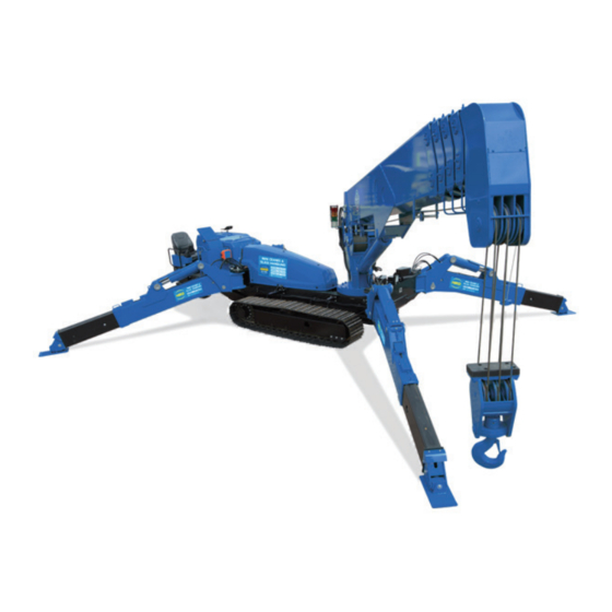
3. MACHINE OVERVIEW 3.1 SPECIFIED OPERATIONS This machine is to be used for the following operations: • Crane operation This machine is a mobile crane mounted on a crawler-type carrier and equipped with a boom-type crane. This self-propelled crane is capable of moving (travelling) in the worksite and lifting an object weighing up to the rated total load. -
Page 14: Machine Functions
This machine is composed of the following units and systems: [1] CARRIER The carrier consists of the travelling gear, engine, travelling operation unit, and crane operation unit. [2] CRANE The crane consists of the telescopic boom, boom derricking system, slewing system, hook block, winch system, and outrigger system. -
Page 15: Qualification For Operation
4. QUALIFICATION FOR OPERATION • A high incidence of occupational accidents in crane operation has been reported. Be aware that experienced crane drivers are no exception. • Warnings and precautions defined in this manual shall be observed for safety assurance during operation of the machine. 4.1 QUALIFICATION FOR CRANE OPERATION Only personnel that have obtained the required license or training stipulated by laws and regulations applicable to the place of use are qualified to operate this machine. -
Page 16: Terminology
5. TERMINOLOGY 5.1 TERMS AND DEFINITIONS [1] RATED TOTAL LOAD Is the maximum load that can be applied according to the boom length and angle. The load includes the mass (weight) of hoisting accessories (hooks) and slinging ropes. [2] RATED LOAD Is a load derived by subtracting the mass (weight) of hoisting accessories (hooks) and slinging ropes from the rated total load. -
Page 17: Diagram Of Working Radius And Lifting Height
5.2 DIAGRAM OF WORKING RADIUS AND LIFTING HEIGHT • The working radius/lifting height shows relationship between working radius, boom angle and lifting height above ground of this machine with no load hoisted, and deflection of the boom is not included. •... -
Page 18: Rated Total Load Chart
5.3 RATED TOTAL LOAD CHART • Rated total load chart is based on that the crane is placed leveled and on firm ground. Depending on the outrigger setting or bad ground conditions the machine may tip over. Be very careful during the work. •... - Page 19 The rated total load chart provides the maximum loads that the crane is capable of hoisting depending on boom length, by working radius. [1] BOOM LENGTH “Boom (1)”, “Booms (1) + (2)”, “Booms (1) + (2) + (3)”, “Booms (1) + (2) + (3) + (4)” and “Booms (1) + (2) + (3) + (4) + (5)”...
- Page 20 4. Booms (1) + (2) + (3) + (4): With booms (2) and (3) fully extended, booms (4) and (5) are in a state of intermediate extension, where half of the “ mark” is exposed from boom (3). If booms (4) and (5) are extended to some extent even only slightly, work should be performed in accordance with the performance of this column.
- Page 21 [2] OUTRIGGER MAXIMUM EXTENSION • Always place all outriggers securely before operating the crane. Unless all of the outrigger monitor lamps are lit except for the boom stowing lamp, interlock function works and, as a result, no crane operation can be performed. •...
- Page 22 [3] OUTRIGGER MEDIUM EXTENSION • Always place all outriggers securely before operating the crane. If not all of the outrigger monitor lamps are illuminates (except for the boom stowing lamp), The interlock system will be activated and, as a result, no crane operation can be performed.
- Page 23 [4] OUTRIGGER MINIMUM EXTENSION • When operating the crane, be sure to set all the outriggers securely. No crane work can be done unless all the lamps are lit up except the boom stowage lamp on the outrigger monitor due to the action of the interlock device. •...
-
Page 24: How To Look At The Angle Indicator
5.4 HOW TO LOOK AT THE ANGLE INDICATOR • When hanging a load, decide the length of the boom (number of boom sections) and boom angle, beforehand. Compare the rated total load to the weight of the baggage hung. Make sure that the total weight of the hoisting accessories, baggage and slinging tools do not exceed that rated total load. -
Page 25: Outline Of Remote Controller
6. OUTLINE OF REMOTE CONTROLLER 6.1 FEATURE This device is to be used for the following operation. This Remote Controller includes both the Transmitter and Receiver which facilitate remote control of the Crane. This is a wireless Remote Controller; the Crane can be operated at the most convenient place away from it within the radio wave range. -
Page 26: Functions
[2] RECEIVER The Receiver which is installed on the Crane is equipped with Control box (1), Monitor LED (2), Connector (3), Antenna (4), etc. Receiver receives operation signals from Transmitter and controls the Crane. [3] ACCESSORIES OF REMOTE-CONTROL TRANSMITTER Waist belt to be worn when using transmitter to prevent accidental dropping of the unit during operation. -
Page 27: Dpf Overview
7. DPF OVERVIEW 7.1 DPF FUNCTION The DPF (Diesel Particulate Filter) is a device which removes PM (particulate matter) from the poisonous exhaust gas. For the DPF to function correctly, be sure to use the specified fuel and engine oil. •... - Page 28 [Stationary Regeneration] (Manual regeneration) Even if automatic regeneration is carried out, if the machine is idling with no load or operations with low load is repeated, the PM may not be regenerated. In this case, the DPF regeneration request lamp on the monitor is lit.
- Page 29 This Page Intentionally Left Blank.
-
Page 30: Safety
SAFETY 1. BASIC PRECAUTIONS 2. PRECAUTIONS ON HANDLING REMOTE CONTROL SYSTEM 3. PRECAUTIONS FOR USE OF ENGINE AND ELECTRIC MOTOR SPECIFICATIONS 4. OPERATION RELATED PRECAUTIONS 5. TRANSPORT PRECAUTIONS 6. BATTERY HANDLING PRECAUTIONS 7. MAINTENANCE PRECAUTIONS 8. SAFETY LABEL LOCATIONS All the safety precautions defined in this manual should always be read and observed. -
Page 31: Basic Precautions
1. BASIC PRECAUTIONS OBSERVE THE MANUAL AND SAFETY LABELS • Read well and understand this manual as well as the safety labels attached to various parts of this Machine. Attempt to drive/operate without understanding fully may result in wrong operation that may cause personal or equipment accidents. - Page 32 USE OF MACHINE THAT WAS RENTED OR PREVIOUSLY USED BY SOMEONE ELSE Check the following subjects in writing before using any Machine that was rented or previously used by someone else. In addition, check the inspection record table for the maintenance conditions such as the periodic inspections.
- Page 33 TEMPORARY STORAGE WHEN ABNORMALITY IS FOUND WITHIN MACHINE In case the Machine is found with an abnormality and is therefore stored temporarily waiting for service, apply following measures to notify all persons in the office that “the use is prohibited due to failure.” •...
- Page 34 SAFETY WHEN REFILLING FUEL • Diesel fuel is used as the fuel of this Machine. Do not refill wrong kind of fuel. Refilling with the wrong kind of fuel may damage the engine. • Always stop the engine before refilling the fuel. Refilling the fuel when engine is running may cause leaked fuel to draw fire from hot silencer or other substance.
- Page 35 BEWARE OF ASBESTOS DUST Inhalation of asbestos dust may result in lung cancer. This Machine does not contain asbestos, but asbestos may be found in the wall, ceiling or other construction locations within the worksite of this Machine. In addition, be careful of the following when working with a material that may contain asbestos.
-
Page 36: Precautions On Handling Remote Control System
2. PRECAUTIONS ON HANDLING REMOTE CONTROL SYSTEM DO NOT MODIFY • Never disassemble or modify the Transmitter, Receiver and accessories. Otherwise, an electric shock or fire may be caused. HOLDING THE TRANSMITTER • See the illustration on the right for the operation method of the Transmitter. - Page 37 Do not allow an object or water to enter the inside of the device. Do not put metals, flammables or water in the battery storage section of the transmitter or the inside of the opening of the battery charger. Do not connect the battery storage section of the transmitter or the terminal section of the inside of the opening of the battery charger with a metal or do not insert a metal into these parts.
- Page 38 PRECAUTIONS IN OPERATION ENVIRONMENT OF REMOTE CONTROL This remote control system cannot be used for operation in a place where there is danger of explosion. USING SPECIFIED EQUIPMENT • Use a specified battery for the remote control system. The use of battery other than specified may cause electrolyte leakage, heat generation and rupture of the battery.
- Page 39 TEMPORARY STORAGE WHEN ABNORMALITY IS FOUND WITHIN THIS SYSTEM In case this system is found with an abnormality and is therefore stored temporarily waiting for service, apply following measures to notify all persons in the office that “the use is prohibited due to failure.”...
-
Page 40: Precautions For Use Of Engine And Electric Motor Specifications
3. PRECAUTIONS FOR USE OF ENGINE AND ELECTRIC MOTOR SPECIFICATIONS PRECAUTIONS ON USAGE The following precautions should always be observed when using this machine. If these, or the engine and electric motor specifications are disregarded, a serious accident may occur. •... -
Page 41: Operation Related Precautions
4. OPERATION RELATED PRECAUTIONS 4.1 BEFORE STARTING ENGINE ESTABLISH SAFETY OF WORKSITE • Confirm that no danger is present at the worksite before starting work. • Investigate the ground and road surface condition of the worksite and decide the best working method. •... - Page 42 CAUTIONS WHEN STARTING ENGINE • Make sure no person or object is within the boom slewing radius area before starting the engine. • Honk the horn for warning before starting the engine. • Do not start the engine by short-circuiting the starter circuit. This may cause a fire.
-
Page 43: After Starting Engine
4.2 AFTER STARTING ENGINE INSPECTION AFTER STARTING ENGINE Omitting the inspections after starting the engine results in delay to discover the Machine abnormalities, and may result in accidents and Machine damages. Inspection should be carried out in a clear area. No unauthorized persons should be able to approach the Machine. - Page 44 CAUTIONS WHEN TRAVELLING Always observe the following to prevent serious injuries and accidental death when moving the Machine. • Do not attempt looking sideways or other dangerous act when driving. • Do not over speed, start moving/stopping/slewing suddenly, or meander since such acts are dangerous. •...
- Page 45 BE CAREFUL OF TRIPPING ON UNSTABLE GROUND Always observe the following to prevent serious injuries and death accidents when travelling over an unstable ground for unavoidable reasons. • Do not enter soft ground area. The machine may get stuck. • The ground near cliff, roadside and deep gully is unstable, so avoid going near such ground.
- Page 46 CAUTIONS UNDER COLD WEATHER • After end of the work, wipe off and put on a cover if substances such as condensation, snow or mud are stuck to the wire harness, connector (1), switches, sensors or similar part. If the infiltrated condensation and/or similar substance freeze, the Machine may operate improperly upon the next use and cause unexpected accidents.
- Page 47 OPERATION CHECK OF OUTRIGGER MODE BY TRANSMITTER AND CAUTIONS DURING OPERATION (REMOTE CONTROL SYSTEM) • Check that position pins and retainers of the outriggers are securely set. • By using mode selector switch (8), set to “1,4 Outrigger mode” or “2,3 Outrigger mode”. •...
-
Page 48: During Crane Work
4.3 DURING CRANE WORK INSPECTION BEFORE STARTING WORK Check that the safety devices and crane operate properly. • Operate each of the operation levers and switches under no load, and check that operations take place without abnormality. Repair immediately if any abnormality exists. •... - Page 49 PLACE CRANE ON LEVEL AND HARD SOIL • Always place the outriggers on a level, stable and solid ground. Attempt to operate the crane without outriggers firmly contacting the ground may cause the Machine to trip. • Always place all outriggers before operating the crane. •...
- Page 50 CAUTIONS WHEN PLACING OUTRIGGER • Do not let people approach the machine when placing the outriggers. Otherwise, serious accidents such as feet being trapped may occur.
- Page 51 BEWARE OF ELECTRICAL CABLE ABOVE • Do not let the Machine touch the electrical cables above. High voltage cables may also inflict electrical shock by close proximity. • Slinging operators are likely to suffer electrical shocks. Always observe the following to prevent accidents. •...
- Page 52 MEASURES WHEN CHARGE ACCIDENT OCCURS If a charge accident occurs, react calmly and take measures in the following procedure. 1. Report Immediately report to the electricity company or related management company, and receive instructions for the power transmission stop, emergency procedures and related matters. 2.
- Page 53 PAY ATTENTION TO WEATHER INFORMATION • A risk of lightning exists in case of a thunderstorm, so abort operating the crane, immediately lower the load and retract the boom. • Wind can cause the hoisted load to move back and forth, which could cause the machine to become unstable.
- Page 54 CAUTIONS WHEN SLINGING • Check the following before hoisting a load. Attempt to hoist the load without checking may result in serious accidents by dropping the load or tripping. • Observe the values in the rated total load chart. • Hoist from the centre of gravity of the load. •...
- Page 55 CAUTIONS WHEN OPERATING CRANE • Be sure to check that the Override switch is at the “OFF” position before operating the crane. Do not attempt to operate the crane with the Override switch kept set to the “ON” position. Use the Override switch only when the safety device have failed or when conducting a load test, or when cancellation of activation stop is desired as necessary.
- Page 56 CAUTIONS ABOUT HIGH TEMPERATURE OIL WHEN OPERATING CRANE When hydraulic oil temperature exceeds 80 °C, high pressure hoses and seals can be damaged by heat, and it may cause burning to skin from oil spray. If temperature of hydraulic oil exceeds 80 °C, stop the operation and wait until the oil cools down.
- Page 57 CAUTIONS WHEN OPERATING BOOM • Perform operation lever operation slowly. Especially avoid sudden lever operations when the load is hoisted, which may cause the load to waggle and give large impact to the Machine, and thus may damage the crane or trip the Machine.
- Page 58 COOPERATION HOISTING IS PROHIBITED AS A GENERAL RULE Cooperation hoisting, where 2 or more cranes are used to hoist a single load, is strictly prohibited. Cooperation hoisting is very hazardous and may cause the machine to fall due to an uneven centre of gravity, unscheduled fall of the hoist load or boom damage.
-
Page 59: Precautions For Terminating Crane Operation (Remote Control System)
4.4 PRECAUTIONS FOR TERMINATING CRANE OPERATION (REMOTE CONTROL SYSTEM) PRECAUTIONS FOR TERMINATING THE OPERATION BY THE TRANSMITTER • Before stowing the outriggers, ensure that the boom and fly jib are stowed in the correct positions. • Before stowing the outriggers, set the operation mode to the “OUTRIGGER MODE” and check that the mode is switched correctly. -
Page 60: Transport Precautions
5. TRANSPORT PRECAUTIONS CAUTIONS WHEN LOADING OR UNLOADING • Be especially careful when loading or unloading the Machine because the risks intervene. • Select a location that is level and has firm road surface when loading or unloading the Machine. In addition, keep enough distance from the roadside. - Page 61 CAUTIONS WHEN LOADING/UNLOADING WITH CRANE Be careful of the following when loading or unloading the Machine by hoisting with a crane. • When hoisting the machine, do not use the brackets on the top face of the boom. • When hoisting the machine, attach slings (1) such as shackles to the holes (4 locations) of outrigger rotary and hang wire ropes (2) (4 pieces) on the hook (3).
-
Page 62: Battery Handling Precautions
6. BATTERY HANDLING PRECAUTIONS CAUTIONS WHEN HANDLING BATTERY The battery fluid contains diluted sulphuric acid and generates hydrogen gas, and causes accidents and fires if handled improperly, so always observe the following precautions: • Do not let a cigarette or any fire source approach the battery. - Page 63 CAUTIONS WHEN CHARGING BATTERY Improper handling when charging the battery may cause the battery to explode. Follow the manuals attached to the Machine and the charger, and always observe the following. “OPERATION CAUTIONS CHARGING BATTERY” for details. • Carry the charger to a location with good ventilation, then remove the battery cap.
-
Page 64: Maintenance Precautions
7. MAINTENANCE PRECAUTIONS 7.1 PRECAUTIONS BEFORE MAINTENANCE FAILURE REPORT Execution of maintenance not described in our manual may cause unexpected failures. Ask us or our sales service agency for repair. CLEAN BEFORE INSPECTION OR MAINTENANCE • Before starting an inspection or maintenance, clean the Machine and prevent rubbish from entering the Machine and make sure the safety will be ensured during maintenance. - Page 65 HANDLING ILLUMINATION DEVICES • Use explosion proof illumination device when inspecting the fuel, oil, battery fluid or similar substance. Failure to use explosion proof illumination device may cause serious fire and explosion. • Attempt to work without using illumination device in a dark place may cause injury or other issue.
-
Page 66: Precautions During Maintenance
7.2 PRECAUTIONS DURING MAINTENANCE NO ENTRY OF UNAUTHORIZED PERSONNEL Do not allow anyone, other than the necessary personnel, to enter the site during maintenance. Post a guard, if necessary. Take special care in case of polishing, welding work, or digging work. MEASURES UPON FINDING ABNORMALITY DURING INSPECTION •... - Page 67 CAUTIONS WHEN WORKING ON MACHINE • Tidy the footing to avoid falling and always observe the following precautions during maintenance on the Machine. • Do not spill oil or grease. • Always tidy away tools. • Beware of the footing when walking. •...
- Page 68 CAUTIONS DURING WELDING REPAIR Weld in a location with good facility, and, only authorized personnel are permitted to weld. Unauthorized personnel are strictly prohibited since risks such as gas generation, fire and electrical shock are present when welding. The personnel authorized to weld are requested to always observe the following. •...
- Page 69 CAUTIONS WHEN HANDLING HIGH PRESSURE HOSE Oil leaking from high pressure hose may cause fire or accident due to faulty operation. Whenever a damaged hose or loosened bolt is found, abort working and ask us or our sales service agency for a repair. •...
- Page 70 CHECKS AFTER INSPECTION/MAINTENANCE Failure to execute an inspection/maintenance item or failure to check the function and operation of the maintained part may cause an unexpected fault which may result in accidents. Strictly observe the following. • Checks while engine is stopped •...
-
Page 71: Safety Label Locations
8. SAFETY LABEL LOCATIONS These labels should be kept clean at all times. If these labels come off, re-attach the label or replace with a new one. As shown below, there are labels other than safety labels which should be treated in the same way. - Page 72 (3) Total load chart (106-2186300)
- Page 73 (6) Minimum hoisting weight (106-4711700) (2 places) (7) Fixing bracket positions during transportation (8) Caution when traveling on slope (106-4713200) (349-4421100)
- Page 74 (9) Precautions when using(106-2186600)
- Page 76 (12) Washing caution (350-4539700) (15) Hydraulic oil caution (104-4550800) (3 places) (19) Lever patterns (crane mode) (21) Lever patterns (travel mode) (106-3397300) (106-3397400) (23) Do not insert fingers into the hole (CL000100000) (4 places)
- Page 77 (24) Outrigger (mind your feet) (25) Outriggers extended (CL000040000) (CL000110000) (4 places) (29) Read the user manual (CL000010000) (30) Radiator caution (349-4427300) (31) Exhaust gas caution (CL000060010) (32) Open flames prohibited (CL000050000)
- Page 78 (33) Engine cover caution (349-4427900) (34) Caution against rotating parts in the engine room (CL000080010) (35) Burn caution (CL000070010) (2 places) (37) Do not enter under loads (CL000020000) (38) Electric shock caution (553-4267300) (39) Warning(553-4268000) (2 places) (40) Winch entanglement caution (41) Cautions on override switch (CL000090000) (2 places) (585-4739200)
- Page 79 (49) Main unit 4 part hanging positions (51) Outrigger caution (106-4713500) (104-4549601) (4 places) (53) Diesel fuel (585-4738600) (54) Load for 6/4/2 wires hung (106-4714400) (2 places) (55) Main unit total weight (standard specifications) (106-4718500)
- Page 80 (56) Load per single line of 4 part hanging (56) Load per single line of 4 part hanging (standard specification) (engine with electric motor specification) (106-4713400) (4 places) (106-4714000) (4 places) (57) Fire extinguisher caution (103-4604800) (60) EPA regulation (114110-07761) (61) Working radius / Lifting height (64) Cautions when loading machine (Pick &...
- Page 81 This Page Intentionally Left Blank.
-
Page 82: Operation
OPERATION 1. NAME OF EACH SECTION 2. OPERATION 3. OPERATING BY REMOTE CONTROL 4. OPERATING MACHINE WITH ENGINE & ELECTRIC MOTOR 5. HANDLING WIRE ROPE 6. TRANSPORTATION 7. HANDLING MACHINE IN COLD ENVIRONMENT 8. LONG-TERM STORAGE 9. HANDLING BATTERY 10. HANDLING REMOTE CONTROLLER BATTERY 11. -
Page 83: Name Of Each Section
1. NAME OF EACH SECTION 1.1 MACHINE UNITS ( 1 ) B o o m ( 1 3 ) I n v e r t e r p a n e l ( i n s i d e ( 2 7 ) P o w e r s u p p l y b o x ( f o r ( 2 ) B o o m t e l e s c o p i n g m a c h i n e r y c o v e r ) ( f o r m a c h i n e s w i t h e n g i n e... -
Page 84: Description Of Controls
1.2. DESCRIPTION OF CONTROLS (1) Outrigger operation panel (6) Starter switch (11) Override switch (2) Left control lever (7) Lock lever (12) Fuse box (3) Right control lever (8) Accelerator pedal (13) Cigar socket (4) Monitor (9) Light switch (14) Maintenance USB port (5) Emergency stop switch (10) Disconnect switch... -
Page 85: Description Of Monitor
1.2.1. DESCRIPTION OF MONITOR [1] MONITOR DISPLAY (COMMON TO ALL MODES) Date & Time display Pop-up select switch (17) Exhaust temperature Hour meter (up) alarm lamp Engine speed (10) Pop-up select switch Fuel gauge (down) (18) DPF regeneration lamp Eco mode switch / (11) Enter switch (19) Failure Boom lift bypass switch... - Page 86 [1] Date & Time display Displays the current time and date. Example: 17:13 28-08-2015 [2] Hour meter Displays total operation hours of the machine. Use this value as a reference for periodical check intervals. When the starter switch is in the “ON” position with the engine running or the machine power source set to the electric motor, the meter indication increases even if the machine or the electric motor is not working.
- Page 87 [5] Eco mode switch / Boom lift bypass switch When Eco mode is selected, the upper limit for the engine speed in crane mode is set, restricting the fuel consumption. ・N : Normal Mode ・E : Eco Mode (setting upper limit for the engine speed) NOTES Note that Eco Mode can be selected only when the crane is in Crane Mode.
- Page 88 [9] Pop-up select switch (up) Use this switch to select a desired function on the currently displayed pop-up screen. [10] Pop-up select switch (down) Use this switch to select a desired function on the currently displayed pop-up screen. [11] Enter switch Use this switch to select a desired function on the currently displayed pop-up screen.
- Page 89 [14] Engine coolant temperature Indicates an abnormality of engine coolant temperature. It is normal if the monitor remains OFF during operation. Engine coolant temperature is exceeding the normal value if the monitor lights up during operation. Set the engine speed to low idle immediately and wait until the monitor goes OFF (engine coolant temperature drops).
- Page 90 [19] Failure Lights up in case of an engine failure. [20] Emergency stop lamp This lamp is lit when the emergency stop switch is pressed. [21] Light Remains lit while the headlight at the front of the machine is on. [22] Electricity on lamp Lights up when the electric unit is being supplied with electricity.
- Page 91 [2] MONITOR DISPLAY (TRAVELLING MODE) (1) BOOM LENGTH (7) LOAD CAPACITY (10) FRONT VIEW CAMERA (2) BOOM ANGLE (8) MODE SELECTOR MONITOR (3) WORKING RADIUS SWITCH (2) (Travelling (11) LEFT SIDE-VIEW (4) SLEW ANGLE Hi/Low) CAMERA MONITOR (5) RATED TOTAL LOAD (9) MODE SELECTOR (12) Error codes (6) ACTUAL LOAD...
- Page 92 This section explains the parts other than those explained in “1.2.1 DESCRIPTION OF MONITOR [1] MONITOR DISPLAY (COMMON TO ALL MODES)” [1] BOOM LENGTH Continually displays the current boom length during crane operations. NOTES The boom length refers to the straight-line distance from the boom foot pin to the sheave pin at the front end of the boom.
- Page 93 [6] ACTUAL LOAD Continually displays the actual load of the hoisted load during crane operations. This actual load equals the total weight of the hook, sling, and hoisted weight. When no load is applied, the normal indication becomes “0.0” to “0.1”. If the indication does not fall within the above range, contact us or our sales service agent.
- Page 94 [10] Front view camera monitor Displays the view ahead of the machine. To display the view at the left side of the machine, touch the screen. [11] Left side-view camera monitor Displays the left side-view of the machine. To display the view ahead of the machine, touch the screen.
- Page 95 [3] MONITOR DISPLAY (OUTRIGGER MODE) (1) Outrigger (1) Extension (10) Outrigger (2) (MID) (21) Crane stow position (ANGLE SET-UP) (11) Outrigger (3) (MID) (22) Pick & Carry position (2) Outrigger (2) Extension (12) Outrigger (4) (MID) (23) Mode selector switch (2) (ANGLE SET-UP) (13) Outrigger (1) (MAX) (Extension/Ground)
- Page 96 The following explains the monitor items except those described in Section “1.2.1, DESCRIPTION OF MONITOR, [1] MONITOR DISPLAY (COMMON TO ALL MODES)”. [1] Outrigger (1) Extension (ANGLE SET-UP) [2] Outrigger (2) Extension (ANGLE SET-UP) [3] Outrigger (3) Extension (ANGLE SET-UP) [4] Outrigger (4) Extension (ANGLE SET-UP) These lamps individually light up to indicate which outrigger is currently extended.
- Page 97 [21] Crane stow position Illuminates in yellow when the boom has been completely retracted with a boom angle being 0 to 3° and a slew angle being 3 to 6°. Otherwise, illuminates in red. [22] Pick & Carry position Illuminates in yellow when the machine is in Pick & Carry posture.
- Page 98 [4] MONITOR DISPLAY (CRANE MODE) (1) Load capacity ratio indication (14) Actual load indication (ACTUAL LOAD) (2) Lifting height indication (LIFTING (15) Rated total load indication (RATED HEIGHT) TOTAL LOAD) (16) Hook grounding indication (GROUND (3) Lifting height limiter switch (4) Boom angle upper limit switch CONTACT) (5) Boom angle lower limit switch...
- Page 99 The following explains the monitor items except those described in Section 1.2.1, DESCRIPTION OF MONITOR, [1] Monitor Display (common to all modes)”. [1] Load capacity ratio indication Indicates the moment limiter load capacity ratio by lighting up and off of the “Bar” indication. [2] Lifting height indication (LIFTING HEIGHT) Continuously displays the current lifting height during crane operation.
- Page 100 [10] Lifting mode Displays either one of N-mode/P-mode/M-mode which was selected and set on monitor or in the User Initial Mode. The rated total load chart changes by switching the lifting mode, but only when under the following conditions. • N-mode (normal mode) Applies the rated total load chart according to the extended outriggers.
- Page 101 [13] Over winding indication (OVER WINDING) Lights up when the hook is hoisted too high due to over winding of the wire rope during crane operation. [14] Actual load indication (ACTUAL LOAD) Continually displays the actual load of the hoisted load during crane operations.
- Page 102 [18] Boom angle indication (BOOM ANGLE) Continually displays the current boom angle during crane operations. NOTES The boom angle refers to the angle which the boom forms with the horizontal line. [19] Slew angle indication (SLEW ANGLE) Shows the current slewing angle when operating the crane.
- Page 103 [23] Pick & Carry position Illuminates in yellow when the machine is in Pick & Carry posture. When this light illuminates in yellow, outrigger can be operated even the crane is not stowed. For conditions of Pick & Carry posture, read the section “OPERATION 2.26 PICK &...
- Page 104 [5] MONITOR DISPLAY (USER INITIAL MODE) (1) Lifting mode (8) Consumables (2) Number of falls (9) Switch operation tone ON/OFF (3) Language setting (10) Switch hook ground detection ON/OFF (4) Error history (11) Switch winch setting in SH mode ON/OFF (5) Software version (Only for machine with searcher hook ) (6) Monitor brightness...
- Page 105 [1] Lifting mode The lifting mode can be switched by touching the screen. ・N : normal mode ・P : power mode ・M : multi-outrigger mode For the details of each mode refer to “OPERATION – 1.2.1 [4] [10] Lifting mode” section. [2] Number of falls The mode can be changed by touching the screen.
- Page 106 [8] Consumables By touching the screen, a list of consumables and the time until their next their replacement can be checked. For the consumables of which scheduled dates for replacement come within 30 hours or 3 days, each of them are displayed in yellow letters with outlined characters, and for those scheduled dates for replacement have been reached, each of them are displayed in red letters with a solid red icon.
-
Page 107: Names And Description Of Control Levers
1.2.2. NAMES AND DESCRIPTION OF CONTROL LEVERS [Traveling mode] [Outrigger mode] [Crane mode] (1) Accelerator up/down (1) Accelerator up/down (1) Accelerator up/down (pop-up up/down) (pop-up up/down) (pop-up up/down) (2) Horn (2) Horn (2) Horn (3) Pop-up Enter (3) Pop-up Enter (3) Pop-up Enter (4) Mode selector switch (4) Mode selector switch... - Page 108 [Travel mode] [1] Accelerator up/down (pop-up up/down) Use these switches to control the engine speed. The engine speed keeps increasing while the up switch is pressed. The engine speed keeps decreasing while the down side is pressed. Use these up and down switches to make a selection on the pop-up screen that appears on the monitor.
- Page 109 [6] Mode selector switch (Travelling/Outrigger/ Crane) Use this switch to change the machine mode. Push to display a pop-up screen. When the pop-up screen appears, you can select the machine mode from “Travel”, “Outrigger” and “Crane” with the up/down select switch ([1] Accelerator up/down (pop-up up/down)).
- Page 110 [Outrigger mode] Only items different from those in the travel mode are described here. [4] Mode selector switch (Extension/Ground) Use this switch to change the outrigger operation. Push to display a pop-up screen. When the pop-up screen appears, you can change the mode between “Extension” and “Ground”...
- Page 111 [7] Unwinding Unwinds the wire rope while the lever is pushed forward. [8] Winding Winds the wire rope while the lever is pulled toward you. [9] Boom lowering Lowers the boom while the lever is pushed towards the right side. [10] Boom raising Raises the boom while the lever is pushed towards the left side.
-
Page 112: Names And Description Of Outrigger Operation Panel
1.2.3 NAMES AND DESCRIPTION OF OUTRIGGER OPERATION PANEL (1) Outrigger (1) switch (2) Outrigger (2) switch (3) Outrigger (3) switch (4) Outrigger (4) switch [1] Outrigger switch These switches can be used to deploy, ground, or stow outriggers. The machine is equipped with four outriggers, (1) to (4), which can be operated independently or simultaneously. -
Page 113: Emergency Stop Switch
1.2.4 EMERGENCY STOP SWITCH Use this switch to stop the engine or the electric motor immediately in case of an emergency due to an abnormality in the machine. • ON: Press the switch. The engine or the electric motor stops. •... -
Page 114: Light Switch
1.2.8 LIGHT SWITCH Use this switch to turn on the headlights equipped on the front of the machine. The pilot lamp on the switch lights up when the switch is set to the “ON” position, and goes out when it is set to the “OFF”... -
Page 115: Override Switch
1.2.10 OVERRIDE SWITCH Override switch has a function to disable the moment limiter. For about 3 minutes from this switch is turned ON, the crane does not automatically stop with the moment limiter and is very dangerous. Any crane operation in such conditions may result in dropping of the hoisted load, breakage of crane boom, and/or machine tipping, and may cause a serious accident resulting in death or serious injury. -
Page 116: Fuse Box
1.2.11 FUSE BOX Before replacing or inspecting fuses, be sure to turn the starter switch to the “OFF” position. CAUTION Fuses protect electrical components and wires from being burnt out. • This machine uses blade fuses. If a fuse is corroded and shows white powder, be sure to change the fuse. -
Page 117: Cigar Socket
1.2.12 CIGAR SOCKET The cigar socket can be used to charge the battery for the radio controller. The cigarette lighter port is below the fuse box. 1.2.13 MAINTENANCE USB PORT This is only used at the time of maintenance. The USB port is located under the fuse box. -
Page 118: Names And Description Of Remote Control Parts
1.3 NAMES AND DESCRIPTION OF REMOTE CONTROL PARTS 1.3.1. TRANSMITTER AND RECEIVER Ttansmitter Receiver (1) Left control lever (C1) Cable connection port (2) Right control lever (L1) LED light (front) (3) Remote controller power ON/OFF switch (L2) LED light (control panel) (4) Engine Start/Stop switch (M1) Left display (5) Operation mode selector switch... - Page 119 [1] Left control lever [2] Right control lever These are joystick control levers, which can be used for crane, outrigger and travelling operations. NOTES These operations cannot be performed at the same time. It is required to change the operation mode with the operation mode selector switch (5).
- Page 120 [M1] Left display Use this display to view various kinds of information. [M2] Right display Use this display to view various kinds of information. [N1] Display operation switch Use this switch to operate the display. [R1] Control box Contains the receiver devices and control devices. Do not disassemble or modify the control box under any circumstances.
- Page 121 [R3] Connector connection port Wiring connector to allow communication with the controller on the machine. The wire must be kept connected. Before performing electric welding due to repair work for the machine body or other reasons, be sure to disconnect the wire. Failure to do so may result in a machine failure caused by burn damage to the control box due to high voltage applied to it.
-
Page 122: Description Of Remote Controller Accessories
1.3.2 DESCRIPTION OF REMOTE CONTROLLER ACCESSORIES [1] WAIST BELT (1) Wear the belt when you operate the Transmitter. • Wear the waist belt around your waist. • Attach the Transmitter to the waist belt. [2] BATTERY CHARGER FOR REMOTE CONTROLLER Battery charger for charging the remote controller. -
Page 123: Outrigger Safety Device
1.4. OUTRIGGER SAFETY DEVICE 1.4.1 FUNCTIONS OF OUTRIGGER SAFETY DEVICES The outrigger safety devices have the interlock functions shown in the table below. Interlock Function Description The outriggers will not operate unless the boom is in stowage position (in the slew stowage position, fully retracted and fully Outrigger Interlock lowered position), and the positioning pins are securely inserted with the outrigger rotaries slewed to the extension side... -
Page 124: Moment Limiter (Overload Detector)
1.5 MOMENT LIMITER (OVERLOAD DETECTOR) 1.5.1 CONFIGURATION OF MOMENT LIMITER (1) Monitor (5) Boom length gauge (inside the boom) (2) Override switch (6) Boom angle indicator (Both side faces at (3) Controller the rear end of the boom) (4) Tricolor revolving light (7) Pressure sensor (derricking cylinder (A) Red revolving light (warning lamp for a section, 2 pieces) -
Page 125: Functions Of Moment Limiter
1.5.2 FUNCTIONS OF MOMENT LIMITER • Do not remove or disassemble, or repair any detectors, such as the boom angle gauge, boom length gauge, or pressure sensor. Never reposition the detector from the original location to another. • When an object hits the detector or damage is found on it, be sure to check the operating condition of the automatic stop. -
Page 126: Moment Limiter Operation
[2] MOMENT LIMITER ERROR MESSAGE DISPLAY The moment limiter is equipped with a self- diagnostic function at its display section in order to detect the occurrence of an abnormality, such as disconnection of wires or connectors, failure in the boom angle, boom length gauge, or in the pressure sensor. The moment limiter notifies the operator of the detected results by using error codes, which are displayed on the monitor. - Page 127 4. RECOVERY OPERATION FROM AUTOMATIC STOP To recover from the overload condition, perform one of the following so as to operate the crane in reverse order when it is automatically stopped. (1) Unwind the wire rope to lower the hook, and place the suspended load on the ground. (2) Retract the boom.
-
Page 128: Moment Limiter Settings
1.5.4 MOMENT LIMITER SETTINGS [1] NUMBER OF WIRE FALLS SELECTOR SWITCH As to the number of wire falls, check the actual number of wires, and set the correct value. If the setting is incorrect, the crane fails to stop automatically even when the suspended load is approaching overload due to a warning alarm that fails to go off. - Page 129 [3] BOOM ANGLE LOWER LIMIT SWITCH Use this switch to set or reset the boom angle lower limit. [Setting] With no value being set for the lower limit angle, move the boom to an angle you want to set as an upper limit angle, and push and hold the switch for 2 seconds.
- Page 130 [Resetting] To reset the upper limit value that has been set (the indicator lamp is illuminating in orange), push and hold the switch for 5 seconds. The currently effective upper limit value will be reset. At the same time the illuminated orange indicator lamp at the switch turns blue to indicate that the set value for the upper limit has been reset.
-
Page 131: Moment Limiter Functions
[6] CLOCKWISE/COUNTER-CLOCKWISE SLEW ANGLE LIMITER SWITCHES Use these switches to set or reset the upper limit angles for the boom slew angle. [Setting] With no value being set for the upper limit angle, rotate the boom to an angle you want to set as an upper limit, and push and hold the switch for 2 seconds. - Page 132 [2] WORKING RADIUS LIMITER ALARM When the boom is approaching the predetermined working radius limit, the alarm goes off to alert the operator and people around the machine. The set values for the working radius limit will remain memorized even after the starter switch is set to the “OFF”...
- Page 133 [4] NUMBER OF EIRES HUNG CHANGE DISPLAY • Before changing the number of wires hung with the switch for changing the number of wires hung, be sure to stop the ongoing crane operation. Changing the number of wires hung during crane operation may result in an unexpected accident. •...
-
Page 134: Moment Limiter Start Conditions
[8] EXCESSIVE UNWIND DETECTOR When the hook is unwound and the length of the wire rope remaining in the winch drum becomes short, the following occur: • “OVER UNWINDING” indication blinks in red. • When hook unwinding operation is performed, the alarm issues an intermittent sound “peep”. -
Page 135: Override Switch
1.5.7 OVERRIDE SWITCH Override switch has a function to disable the moment limiter. For about 3 minutes from this switch is turned ON, the crane does not automatically stop with the moment limiter and is very dangerous. Any crane operation in such conditions may result in dropping of the hoisted load, breakage of crane boom, and/or machine tipping, and may cause a serious accident resulting in death or serious injury. -
Page 136: Over Hoist Detector
1.6 OVER HOIST DETECTOR CAUTION When winding the hook block, be careful of clearance between the hook block and boom. Also, the hook block can be wound when the boom is extended. Perform boom extension operation while always checking the hook block height. (1) Hook block (2) Over hoist detector (3) Weight... -
Page 137: Operator Seat
1.7 OPERATOR SEAT (1) Back seat (2) Seat (3) Slide adjustment lever (4) Reclining adjustment lever (5) Arm rest (6) Seatbelt • Before driving and operating the machine, be sure to adjust the operator seat. Be sure to adjust the operator seat particularly after use by other operators. •... - Page 138 [3] ARM REST The arm rest (5) can be folded up towards the back of the seat (1). NOTES Before getting in or off the machine, be sure to fold up the arm rest. [4] SEATBELT • Before wearing the seatbelt, check the seat belt and the seatbelt brackets for damage or defects.
-
Page 139: Radiator Cover
1.8 RADIATOR COVER • Before removing the radiator cover, be sure to stop the engine and remove the key from the starter switch. • Do not remove the radiator cover immediately after operation while the engine is still hot. [1] REMOVING RADIATOR COVER Remove the radiator cover with the following procedure when performing... -
Page 140: Radiator Grille
1.9 RADIATOR GRILLE • Before removing the radiator grille, be sure to stop the engine and remove the key from the starter switch. • Do not remove the radiator grille immediately after operation while the engine is still hot. Since the radiator grille is relatively big in size, and mounted high on the machine, the radiator grille must be removed or installed by two or more people. -
Page 141: Engine Cover
1.10 ENGINE COVER • Before removing the engine cover, be sure to stop the engine and remove the key from the starter switch. • Do not remove the engine cover immediately after the operation while the engine is still hot. Since the engine cover is relatively big in size, and mounted high on the machine, the engine cover must be removed or installed by two or more people. -
Page 142: Machinery Cover
1.11 MACHINERY COVER • Before removing the machinery cover, be sure to stop the engine and remove the key from the starter switch. • Do not remove the machinery cover immediately after operation while the engine is still hot. Since the machinery cover is relatively big in size, and mounted high on the machine, the machinery cover must be removed or installed by two or more people. -
Page 143: Operation Side Cover
1.12 OPERATION SIDE COVER [1] REMOVING THE OPERATION SIDE COVER Remove the operation side cover with the following procedure when performing inspection/maintenance inside the operation side cover: 1. Remove the 10 bolts (2) on the operation side cover (1). 2. Remove the operation side cover (1). [2] INSTALLING THE OPERATION SIDE COVER HATCH When you are finished with inspection/maintenance inside the operation side cover, install the operation side cover with the following procedure:... -
Page 144: Power Unit
1.13 POWER UNIT 1.13.1 NAMES OF POWER UNIT PARTS (1) Electric motor (2) Coupling (3) Hydraulic pump 1.13.2 NAMES OF POWER SUPPLY BOX PARTS (1) Power supply box (4) Cable gland (7) Cover (2) Power supply box door (5) Breaker switch (3) Power supply box handle (6) Breaker switch block... -
Page 145: Names Of Inverter Parts
[1] BREAKER SWITCH • Be sure to put the breaker switch into the “OFF” position if this machine is not connected to a power supply or after work has finished. • If during operation, the breaker automatically enters the “OFF” position, a fault has occurred somewhere such as around the inverter panel, around the electric motor or the electric wiring. -
Page 146: Operation
2. OPERATION 2.1 PRE-OPERATION INSPECTION Before starting the day’s work, perform the following checks: For check items in the pre-operation inspection, refer to “INSPECTION AND MAINTENANCE 8. MAINTENANCE AND INSPECTION LIST”. 2.1.1 VISIBLE CHECKS Refer to “INSPECTION AND MAINTENANCE 9.1.1 CHECKING BEFORE STARTING ENGINE ( VISUAL CHECKS)”. -
Page 147: Starting Engine
2.2 STARTING ENGINE • Before starting the engine, make sure no personnel or impediments are close to the machine and honk the horn. 2.2.1 NORMAL STARTING OF ENGINE CAUTION • If the ambient temperature is too low to start the engine, try again by following the instructions described “OPERATION... -
Page 148: Starting Engine In Cold Environment
2.2.2 STARTING ENGINE IN COLD ENVIRONMENT CAUTION • Do not keep the starter turned for more than 5 seconds. Doing so will accelerate battery discharge. If the engine fail to start, wait for 1 minute before retrying. • Verify that the fuel lever of the water separator pot is in the vertical position (open) before starting the engine. -
Page 149: Operations And Checks After Starting Engine
2.3 OPERATIONS AND CHECKS AFTER STARTING ENGINE Never refuel (diesel fuel) while the engine is in operation. Always stop the engine before refilling fuel. • If any abnormal condition occurs in the machine during engine warm-up, immediately push the engine emergency stop switch to bring the engine to an emergency stop. Then, turn the starter switch key to the “OFF”... - Page 150 6. Operate the right control lever (1) slowly right and left and move the derrick cylinder up and down until it reaches the stroke end while checking if there is any abnormality with the operation. Repair if any abnormality is found. 7.
-
Page 151: Break-In Operation
2.4 BREAK-IN OPERATION Perform break-in for the period of about the first “250 hours” (hours displayed on the service meter). The service life of the machine shortens if heavy loads are applied to the operation or the engine before the break-in period for each section of the machine elapses. While this machine is shipped after thorough adjustment and inspection, immediate difficult tasks will quickly degrade the functions and shorten the life of the engine and crane. -
Page 152: Start Moving Machine
2.6 START MOVING MACHINE • Do not allow anyone around the machine. • Clear away all the obstacles on the travelling path. Check for projections and grooves on the ground surface where the machine travels especially when it travels backwards. Remove obstacles from the surface if required. •... -
Page 153: Changing Machine Travelling Mode
2.7 CHANGING MACHINE TRAVELLING MODE • Drive the machine at speeds appropriate for the ground or road conditions. Other than adjusting the amount that you shift the control lever, you can change the travelling speed by changing the position of the hi speed travelling change switch to “Hi Speed Travelling Mode”... - Page 154 [2] SPIN TURNS • LEFT SPIN TURN Pushing the right control lever forward while pulling the left control lever toward you will rotate the crawler belts in opposing directions, allowing machine spin counter-clockwise. • RIGHT SPIN TURN Pushing the left control lever forward while pulling the right control lever toward you will rotate the crawler belts in opposing directions,...
-
Page 155: Stopping/Parking The Machine
2.9 STOPPING/PARKING THE MACHINE • Avoid sudden stops and try to stop with a safety margin whenever possible. • Choose a level and solid location for parking the machine. If it is necessary to park on a slope, provide some blocks so that the machine will not move. -
Page 156: Stopping Engine
2.10 STOPPING ENGINE CAUTION • Stopping the engine before it sufficiently cools down may shorten the life of engine units. Do not stop the engine suddenly except for an emergency. • When the engine is overheated, do not stop the engine suddenly. Change the engine speed to low, and gradually cool down the engine before stopping. -
Page 157: Cautions In Driving
2.12 CAUTIONS IN DRIVING Not observing these cautions while driving will result in serious accidents. [1] CAUTIONS IN DRIVING Driving over boulder stones or a stump not only causes overturning of the machine, but also gives an impact to the machine (especially around crawlers), causing breakage. - Page 158 • Drive the machine at as low a speed as possible when driving down a slope by operating the accelerator pedal and control levers. Shifting the control lever into the “NEUTRAL” position automatically brakes the machine; however, driving down a slope at high speed may cause the machine to overrun. •...
-
Page 159: Outrigger/Crane Related Safety Devices
2.13 OUTRIGGER/CRANE RELATED SAFETY DEVICES Before operating the crane, be sure to understand the following operating procedures, the alarm indications arising from the machine conditions detected by the safety devices, and the detailed actions of shutdown operations. Bearing the above in mind, always ensure safety when you operate the machine. - Page 160 [3] CRANE STOWAGE OPERATION Standard operating procedures/ Operation of safety Indication and Alarm Machine conditions devices • Crane stowage lamp lights up • One of the tricolor revolving lights, lights up according to the load capacity ratio being applied, after comparison between actual operation and Rated Total Load.
- Page 161 [5] OUTRIGGER STOWAGE OPERATION Standard operating procedures/ Operation of safety Indication and Alarm Machine conditions devices Implementing outrigger stowage operation • Outrigger grounding lamp (red) 1. Implementing outrigger blinks Crane Interlock ground stowage operation [Tricolor revolving light (red) • If any one of the 8 •...
-
Page 162: Outrigger Setting Operation
2.14 OUTRIGGER SETTING OPERATION • GROUND FOR SETTING OUTRIGGERS Always place the outriggers on a level, stable and solid ground. Attempting to work with the crane without setting the outriggers may cause the machine to overturn. • OUTRIGGER SAFETY DEVICE Before operating any outrigger, be sure to set the emergency stop switch to the “OFF”... - Page 163 • SELECTING LOCATION TO SET OUTRIGGERS • When setting the outriggers on the structural objects such as construction site or concrete floor, verify in advance that the surface where the outriggers will be set has sufficient strength. Insufficient strength in the setting surface will result in machine overturning or falling due to the setting surface collapsing.
-
Page 164: Outrigger Components
2.14.1 OUTRIGGER COMPONENTS (1) Positioning pin (5) Outer box (2) Outrigger rotary (6) Inner box (3) Outrigger ground contact cylinder (7) Outrigger adapter (plate) (4) Outrigger extension cylinder 2.14.2 OUTRIGGER SETUP OPERATION [1] TASKS TO BE PERFORMED BEFORE STARTING THE ENGINE There are 4 outriggers installed on the machine. - Page 165 3. Change the mode to Outrigger mode with the mode selector switch (1) (Travel/Outrigger/Crane) on the monitor or the left control lever. 4. Make sure that the crane stowage (1) lamp on the monitor is lit in yellow. 5. Select the Manual mode with the mode selector switch (3) (Manual/Auto) on the monitor or the left control lever.
- Page 166 9. Make sure that all of the four outrigger extension lamps (2) on the monitor are lit in yellow. NOTES The crane stowage lamp (1) and four outrigger extension lamps (2) on the monitor stay on. [2] OPERATIONS AFTER STARTING ENGINE If the machine tilts at an angle of “3 degrees”...
- Page 167 6. Select the Ground mode with the mode selector switch (2) (Extension/Ground) on the monitor or the left control lever. 7. Set outrigger switches individually simultaneously to the “Extension” position. When the adapters have touched the ground, with the grounding cylinder extended, set the switch to the “NEUTRAL”...
- Page 168 When the machine is raised up to a height of about 50 mm from the ground, adjust the machine so that the machine is in a horizontal position while checking the position of the yellow bubble in the leveling instrument. At this point, if “automatic” is selected for the mode selection switch (3), the machine is automatically leveled so that it is in horizontal condition.
-
Page 169: Cautions Before Crane Operation
2.15 CAUTIONS BEFORE CRANE OPERATION Not observing these cautions before operation may result in serious accidents. • Make sure that the override switch is in the “OFF” position. The operation does not stop if the override switch is in the “ON”... -
Page 170: Operation Before Crane Work
2.16 OPERATION BEFORE CRANE WORK CAUTION • Before operating the crane, make sure that all lamps on the outrigger indications are lit in green. Crane operation cannot be performed if any one of the four outrigger extension lamps and the four outrigger grounding lamps on the monitor is blinking. •... -
Page 171: Crane Operation Posture
2.17 CRANE OPERATION POSTURE To proceed to the crane operation from the state mentioned in “OPERATION 2.16 OPERATION BEFORE CRANE WORK”, bring the crane into a state ready for operation by following the steps mentioned below. 1. Push the right control lever (1) forward to unwind the wire rope to an extent that the hook block does not come into contact with the ground. -
Page 172: Winding And Unwinding
2.18 WINDING AND UNWINDING • With the boom deflection, the hoisted load slightly shifts forward. Notify the workers around such as slinging operators. • If the hook block is wound excessively, over-winding is detected, and an alarm buzzer sounds. In such a case, immediately shift the right control lever (1) into the “NEUTRAL”... -
Page 173: Boom Telescoping Operation
2.20 BOOM TELESCOPING OPERATION • Operate the left control lever as slowly as possible. Especially avoid sudden lever operations when the load is hoisted, which may cause the load to waggle and give a large impact to the Machine, and thus may damage the crane or trip the Machine. -
Page 174: Slewing Operation
2.21 SLEWING OPERATION • Check it is safe in the vicinity and honk the horn before slewing. • Operate the left control lever as slowly as possible. Make sure to start smoothly, slew at low speed, and stop quietly. Especially avoid sudden lever operations when the load is hoisted, which may cause the load to waggle and cause the Machine to lose balance, and thus may damage the crane or trip the Machine. -
Page 175: Crane Stowage Operation
2.23 CRANE STOWAGE OPERATION The hook stowage switch is used to cancel the automatic stop function of the over winding detector. Take sufficient care not to trap hands or objects when stowing the hook block. CAUTION • Before stowing the hook block, stop the hook block from swaying. •... - Page 176 4. Operate hook raising or hook lowering to adjust hook position and secure the hook block to the hook stowage wire. NOTES If the hook block is excessively wound, the over hoist detector is activated, generating an alarm buzzer. This allows the winding operation to automatically stop.
- Page 177 [Automatic stowage] When automatically stowing the crane, check that there are no interfering objects in the surrounding area before doing so. If you feel danger during automatic stowage, immediately stop the operation. Automatic stowage can be stopped by pressing the emergency stop switch, or by operating the monitor or crane.
-
Page 178: Outrigger Stowage Operation
2.24 OUTRIGGER STOWAGE OPERATION • Do not let people approach the machine when stowing the outriggers. Close proximity to the machine may cause serious accidents such as getting caught between the outrigger and the machine main unit. • Before stowing the outriggers, check that there are no obstacles under the crawler belts. - Page 179 1. Shift the lock lever (1) into the free (F) position. 2. See “OPERATION 2.2 STARTING ENGINE” to start the engine. 3. Take your foot off the accelerator pedal (6) to allow the engine to run at idle. 4. Change the mode to Outrigger mode with the mode selector switch (1) (Travel/Outrigger/Crane) on the monitor or the left control lever.
- Page 180 7. Select the Ground mode with the mode selector switch (2) (Extension/Ground) in the monitor or the left control lever. 8. Identify the outrigger to be operated by checking the outrigger number shown on the operation nameplate attached to each outrigger switch on the outrigger operation panel.
- Page 181 13. Set the two outrigger switches individually or at the same time to the “Retraction” position. When the extension cylinder is completely retracted and the inner box reaches the shortest position, and set the switch to the “NEUTRAL” position. Repeat the above steps for other outriggers to bring the outrigger inner boxes to the shortest position, and set the switch to the “NEUTRAL”...
-
Page 182: Prohibited Operations During Crane Work
2.25 PROHIBITED OPERATIONS DURING CRANE WORK • Always set the outriggers on level, solid ground when performing the crane operations. • Never perform travelling hoist or crane operations without setting the outriggers. The machine will be unstable and overturn, leading to serious accidents. •... - Page 183 [5] DON'T ALLOW ACCESS INTO WORKING RADIUS Do not allow personnel to approach the working radius such as letting operators enter under a hoisted load. [6] DON'T USE FOR OTHER THAN MAIN APPLICATIONS Do not move people up/down with the crane. [7] DON’T PERFORM UNREASONABLE OPERATIONS Operations requiring more than the machine performance can cause accidents.
-
Page 184: Pick & Carry Operation
2.26 PICK & CARRY OPERATION 2.26.1 CAUTIONS DURING PICK & CARRY OPERATION Pick & carry makes the machine very unstable and involves danger, and is not recommended. If you have to perform pick & carry, the load must be within the values shown in the “Pick &... -
Page 185: Pick & Carry Posture
2.26.2 PICK & CARRY POSTURE 2.26.2.1 CHANGE TO PICK & CARRY POSTURE FROM TRAVELLING POSTURE When changing machine from travelling posture to pick & carry posture, be sure to carry it out on level and firm ground. Otherwise it may cause tipping of the machine. 1. -
Page 186: Change To Pick & Carry Posture From Crane Mode Posture
2.26.2.2 CHANGE TO PICK & CARRY POSTURE FROM CRANE MODE POSTURE 1. If the machine is hoisting a load, unload and make no-load condition. 2. Set the crane to the below conditions • Boom is fully retracted • Boom angle is more than 60 degrees •... -
Page 187: Pick & Carry Operations
2.26.3 PICK & CARRY OPERATIONS • Read the items described in “OPERATION 2.26.1 CAUTIONS DURING PICK & CARRY OPERATION” when performing pick & carry duties for safe operation. • Read “OPERATION 2.26.2 PICK & CARRY POSTURE” when to prepare pick & carry posture. -
Page 188: Canceling Pick & Carry Operation Posture
2.26.4 CANCELING PICK & CARRY OPERATION POSTURE NOTES This process is for after the Pick & Carry operation. If the mode is not in Pick & Carry, shift the mode to Pick & Carry first. 2.26.4.1 HOW TO RETURN TO TRAVELLING POSTURE 1. -
Page 189: How To Return To Crane Posture
7. Make sure the crane stowage lamp (1) (yellow) lights on the monitor. NOTES If the crane stowage lamp (1) (yellow) is not lit, fully retract or fully lower the boom, or operate slewing again. 8. Shift to the normal Travel mode with the mode selector switch (3) (Pick &... -
Page 190: Dpf Stationary Regeneration Method
2. 27 DPF STATIONARY REGENERATION METHOD Take care of the following when carrying out DPF stationary regeneration. • Due to the burning / removal process, the temperature of the exhaust gas rises to about 600°C. Do not touch or come close to the DPF muffler, exhaust pipe or exhaust gas. -
Page 191: Operation By Remote Ccontrol
3. OPERATION BY REMOTE CONTROL • Never attempt to dismantle or modify the Transmitter and Receiver. Otherwise, an electric shock or fire may be caused. • Avoid dropping or hitting the Transmitter. A damaged part of the enclosure allows water to enter inside that can cause trouble or failures and may result in a serious hazard, such as a malfunction or electrical shock. -
Page 192: Powering On
3.2 POWERING ON Press the remote controller power ON/OFF switch (3) once, and make sure that the power indicator on the upper left corner of the left display (M1) blinks in green. “Enter start sequence” appears on the right-side monitor (M2) when the remote controller is preparing to be powered ON. -
Page 193: Indications Of Display
3.3 INDICATIONS OF DISPLAY (1) Battery icon Blinks in green when the power supply is in normal condition. (2) Battery status bar Indicates the remaining battery levels as follows: (3) Radio wave status bar The intensity of radio waves are as follows: (4) Error icon An icon appears when an error is detected. - Page 194 [Error indications] If an error is detected, an error is displayed on the right display. The details of the error can be checked from the radio controller menu inside the setting menu. [Crane menu] Pressing the operation mode selector switch (5) will automatically display the screen on the right-side monitor (M2), according to the operation to be performed.
- Page 195 [Settings menu] When the crane menu is displayed, pressing the display operation switch (N1) changes the current menu to the settings menu. Turning the display operation switch (N1) allows you to select a desired menu. Select a menu on the display, and press the display operation switch (N1) to determine the menu.
- Page 196 • Remote control menu...
-
Page 197: Starting/Stopping The Engine
3.4 STARTING/STOPPING THE ENGINE [STARTING THE ENGINE] 1. Raise the lock lever (1) to the lock position (L). NOTES Engine does not start unless the lock lever (1) is in lock position (L). 2. Pressing the engine start/stop switch (4) when the engine is stopped will allow the engine to start. -
Page 198: Travel Operation
3.6 TRAVEL OPERATION 1. Turn the starter switch on the machine to the “ON” position. 2. Press the power ON/OFF switch (3) for the remote control transmitter to supply power to the transmitter. For details about the power-on, refer to “OPERATION 3.2 POWERING ON”. -
Page 199: Changing Direction Of The Machine
3.6.2 CHANGING DIRECTION OF THE MACHINE • Sudden steering or unnecessary spin turns at high speeds not only damages the crawler belt or hydraulic devices, but also may result in a collision with other objects. Stop the machine, and then adjust the engine speed to low before performing spin turns. -
Page 200: Stopping/Parking The Machine
[3] CHANGING DIRECTION WHILE MOVING • LEFT TURN WHILE MOVING FORWARD While pushing the right control lever (2) forward, move only the left control lever (1) back to the “NEUTRAL” position. • LEFT TURN WHILE MOVING BACKWARD While pulling the right control lever (2) toward you, move only the left control lever (1) back to the “NEUTRAL”... -
Page 201: Outrigger Operation
3.7 OUTRIGGER OPERATION • Check if the transmitter operation lever operates smoothly and returns to the Neutral position when your finger is released from it. • The transmitter operation lever will stop due to the stopper when it is turned as far as it will go. -
Page 202: Outrigger Setting Operation
3.7.1 OUTRIGGER SETTING OPERATION Before setting outriggers, read “OPERATION 2.14 OUTRIGGER SETTING OPERATION” and also the precautions described there. 1. See “OPERATION 3.4 STARTING/STOPPING THE ENGINE” to start the engine. 2. Change the mode to Extension with the Transmitter speed selector/Outrigger select switch (6) on the transmitter. - Page 203 4. Change the mode to Extension stowage with the Speed selector/Outrigger select switch (6) on the transmitter. 5. When the grounding cylinder is extended and the adapter is grounded by manipulating the control lever, release your hand from the operation lever. 6.
- Page 204 9. Make sure that all of the four outrigger grounding lamps (3) on the monitor are lit in green. NOTES All of the crane stowage lamp (1), the four outrigger extension lamps (2) and four outrigger grounding lamps (3) are lit in green. CAUTION If any of the outrigger grounding lamps (3) are blinking in red, remove the cover (7) of the outrigger...
-
Page 205: Outrigger Stowage Operation
3.7.2 OUTRIGGER STOWAGE OPERATION Before setting outriggers, read “OPERATION 2. 24 OUTRIGGER SETTING OPERATION” and also the precautions described there. The following explains the setting procedure for only one outrigger (4). Repeat the same procedure for the other three outriggers. 1. - Page 206 4. Change the mode to Extension stowage with the Speed selector/Outrigger select switch (6) for the transmitter. 5. When the grounding cylinder has been extended and the adapter has been grounded by manipulating the control lever, release your hand from the operation lever.
- Page 207 8. Change the mode to Extension/retraction with the speed selector/Outrigger select switch (6) for the transmitter. When the extension cylinder has been completely retracted and the inner box reaches the shortest position, release your finger from the operation lever. Repeat the above step for other outriggers to bring the outrigger inner boxes to the shortest position.
-
Page 208: Crane Operation
3.8 CRANE OPERATION • Ensure that all the outriggers are securely settled, before starting crane operations. Any crane operations where outriggers are improperly used may cause the crane to tip over or other serious accidents. • During crane operations, always refer to the “Rated total load chart” and avoid over-loaded operations. -
Page 209: Hook Winding And Unwinding
3.8.1 HOOK WINDING AND UNWINDING • With the boom deflection, the hoisted load slightly shifts forward. Notify workers in the area such as slinging operators. • If the hook block is wound excessively, over winding is detected, and an alarm buzzer sounds followed by a voice message, “Hook is over-hoisted”. -
Page 210: Boom Telescoping Operation
3.8.3 BOOM TELESCOPING OPERATION • Operate the left control lever as slowly as possible. Especially avoid sudden lever operations when the load is hoisted, which may cause the load to waggle and a give large impact to the Machine, and thus may damage the crane or tip the Machine. -
Page 211: Slewing Operation
3.8.4 SLEWING OPERATION • Check for safety in the vicinity and honk the horn before slewing. • Operate the left control lever as slowly as possible. Make sure to start smoothly, slew at low speed, and stop quietly. Especially avoid sudden lever operations when the load is hoisted, which may cause the load to waggle and cause the Machine to lose balance, and thus may damage the crane or tip the Machine. -
Page 212: Operation While Traveling With A Suspended Load
3.8.5 OPERATION WHILE TRAVELLING WITH A SUSPENDED LOAD Only in Travel mode does it become possible to change the operation mode between Travel and Load carrying by pressing the Load carrying/Fly jib change switch (7). The mode can be changed in the same procedures as those for hoisting/lowering the hook and for derricking the boom. -
Page 213: Operating Speed Selector/Outrigger Select Switch
3.9 OPERATING SPEED SELECTOR/OUTRIGGER SELECT SWITCH Only in the Crane and Travel modes, does it become possible to switch the speed mode between High and Low by pressing Speed selector/Outrigger select switch (6). In the outrigger mode, the outrigger operation mode can be switched between Extension and Extension stowage by pressing the Speed selector/Outrigger select switch (6). -
Page 214: Emergencystop Switch Operation
3.12 EMERGENCYSTOP SWITCH OPERATION • In case of any abnormality in crane operations, immediately press the Emergency stop/Remote controller power OFF switch (10) to stop the engine. The abnormality mentioned above includes: continuation of crane operations even after the release of control levers, or unexpected crane movements before the control levers are used. -
Page 215: Checking After Crane Operation
3.14 CHECKING AFTER CRANE OPERATION 3.14.1 CRANE STOWAGE OPERATION NOTES • Crane stowage operation is recommended by using control levers on the crane. Boom stowage can be operated with radio controller, but it may be difficult to set to the exact slew stowage position. -
Page 216: Operating Machine With Engine & Electric Motor
4. OPERATING MACHINE WITH ENGINE & ELECTRIC MOTOR 4.1 POWER SUPPLY CONNECTION Omitting to follow these precautions may result in serious accidents. • Installation of this machine must comply with laws and regulations of your country. Contact us or our sales service agency if no laws and regulations are applied. •... - Page 217 [If a power plug is not connected] 1. Remove the box (3). The box is attached from the inside with 4 bolts (4). 2. Check that the breaker on the power supply equipment side and the power supply box breaker switch (1) is in the “OFF”...
- Page 218 6. When you are finished, put back the cover (6) of the breaker switch block (5) into place, and close the door (3) of the power supply box (2). 7. Attach the box (3). The box is attached using 4 bolts (4) inside.
-
Page 219: Operation And Checking After Power Connection
4.2 OPERATION AND CHECKING AFTER POWER CONNECTION • Before starting the electric motor, make sure no personnel or impediments are close to the machine and sound the horn. • Always perform the warm-up operation. The motor needs adequate warm-up time especially in cold climates. - Page 220 3. Turn the key to the “START” position. 4. When the electric motor has started, release your hand from the key. The key automatically returns to the “ON” position. 5. Conduct a 5-minute warm-up after the electric motor has started. NOTES This machine offersa power saving function, which is activated when the control levers have been left untouched for 5 minutes after the electric motor started.
-
Page 221: Machine Operation
4.3 MACHINE OPERATION CAUTION After warm-up operation, before operating the crane, see from “OPERATION 2.5 MACHINE TRAVELLING POSTURE” to ”OPERATION 2.25 PROHIBITED OPERATIONS DURING CRANE WORK”. 4.4 MACHINE STOP AND CHECKS AFTER STOPPING MACHINE 1. Turn the starter switch key to the “OFF” position. The electric motor stops. -
Page 222: Power Supply Separation
4.5 POWER SUPPLY SEPARATION 1. Turn “OFF” the power supply equipment breaker. 2. Turn the breaker switch (1) of the power supply box to the “OFF” position. 3. Remove the power plug (2). -
Page 223: Handling Wire Rope
5. HANDLING WIRE ROPE 5.1 CRITERIA FOR WIRE ROPE REPLACEMENT CAUTION • The criteria for replacing wire ropes is common to all the wire ropes for winching, telescoping the boom, and slinging. • The diameter of the wire rope is measured at points where the wire repeatedly runs through the sheave. -
Page 224: Corretive Actions Against Twisted Wire Rope
5.2 CORRETIVE ACTIONS AGAINST TWISTED WIRE ROPE Be sure to wear thick leather work gloves when handling wire ropes. CAUTION On occasion, reverse the ends of the wire rope. Turn the rope end at the hook block side for the end at the winch drum side. This practice helps to extend wire rope service life. - Page 225 6. Start the engine and shift the right control lever into the “Raise” position (push it to the left), and raise the boom until the maximum boom angle is reached. 7. Shift the left control lever into the “Extension” side (push it forward) to fully extend the boom.
-
Page 226: Transportation
6. TRANSPORTATION Observe the related regulations and exercise safety during transport. 6.1 LOADING/UNLOADING • For dimensions and weight, see “SPECIFICATIONS 1. PRINCIPLE SPECIFICATIONS LIST”. • Ramps to be used must satisfy the following conditions: • Must have a length so that the set angle to the truck is 15 degrees or less. •... -
Page 227: Hoisting Machine
4. To load/unload the machine, drive it slowly toward the ramp. At this time, exercise caution so that the boom does not hit the truck. Move backward to load the machine, and forward to unload the machine. 5. On the ramp, do not operate the levers for any purpose other than driving the machine. 6. -
Page 228: Cautions When Loading Machine
6.3 CAUTIONS WHEN LOADING MACHINE •Select a location that is level and has firm road surface when loading or unloading the machine. In addition, keep enough distance from the roadside. •After loading, please make sure if the hook block is secured to the hook stowage wire or to the truck deck. -
Page 229: Handling Machine In Cold Environment
7. HANDLING MACHINE IN COLD ENVIRONMENT 7.1 PREPARING FOR LOW TEMPERATURE In cold conditions, the machine starts to have some difficulty in starting. Take the following actions. [1] LUBRICATION Change the lubricating oil to one with low viscosity. See “INSPECTION AND MAINTENANCE 6.1 USE OF LUBRICATING OIL ACCORDING TO TEMPERATURES”... - Page 230 [4] CAUTIONS AFTER COMPLETING THE OPERATION Observe the following to prevent the machine from not being able to function the next morning because of deposits such as dirt and water and materials around the feet frozen. • Remove dirt and water on the machine. Keep the hydraulic cylinder rod surfaces especially clean to prevent the seal from being damaged with dirt coming into the seals together with the water drops.
-
Page 231: Long-Term Storage
8. LONG-TERM STORAGE 8.1 BEFORE STORING MACHINE CAUTION In order to protect the cylinder rods during long-term storage, the machine must be kept in the “travelling posture”, with the cylinders fully retracted, as shown in the figure to the right. See “OPERATION 2.5 MACHINE TRAVELLING POSTURE”... -
Page 232: After Storage
8.3 AFTER STORAGE If you did not perform antirust operation monthly during the long-term storage, contact us or our sales service agency before using the machine. Perform the following before using the machine after the long-term storage. • Refuel, grease, and change the oil without fail. •... -
Page 233: Handling Battery
9. HANDLING BATTERY Observe the following when handling the battery. • Before inspecting or handling the battery, be sure to stop the engine, and turn the starter switch to the “OFF” position. • Wipe off the dust accumulated on the top of the battery with a moistened cloth. •... -
Page 234: Removing/Installing Battery
9.2 REMOVING/INSTALLING BATTERY CAUTION Verify that the battery does not move after securing the battery. If it moves, secure it again. [1] REMOVAL 1. Remove the floor mat (5) for the driver’s seat. 2. Remove the four mounting bolts (4) and then remove the battery cover (3). -
Page 235: Cautions In Charging Battery
9.3 CAUTIONS IN CHARGING BATTERY When charging the battery mounted to the machine • Abnormal voltage may be applied to the alternator, resulting in a breakage. Disconnect the battery terminal wires before charging the battery. • While charging, remove all the fluid plugs to release the gas generated. •... -
Page 236: Starting Engine With Booster Cable
9.4 STARTING ENGINE WITH BOOSTER CABLE Start the engine with booster cable as described below. [1] CAUTIONS IN CONNECTING/DISCONNECTING BOOSTER CABLE • Never let the (+) terminal and (-) terminal come into contact with the other when connecting the cable. •... - Page 237 [3] STARTING ENGINE Verify that the operation levers of both the slave machine and machine in failure are at the “NEUTRAL” position. If the safety lock lever is equipped, also verify that it is at the lock position. 1. Verify that the clips are securely connected to the battery terminals. 2.
-
Page 238: Handling Remote Controller Battery
10. HANDLING REMOTE CONTROLLER BATTERY NOTES The battery used for the Transmitter is an exclusive battery. 10.1 REPLACEMENT TIMING OF BATTERY When the transmitter battery status bar illuminates in red followed by an alarm signal sound, immediately replace the battery with a charged one. If the battery is not replaced, the Transmitter will stop in a few minutes. -
Page 239: Charging Method Of Battery
10.3 CHARGING METHOD OF BATTERY To charge the battery, use only the supplied battery charger. • Use the battery charger only for charging of the battery described on the model label. • Do not charge the battery in an explosion hazardous area under any circumstances. •... - Page 240 The radio controller battery can be charged using the cigarette lighter port of the vehicle. Set the charger case (B5) for radio controller battery under the override switch.
-
Page 241: Troubleshooting
11. TROUBLESHOOTING 11.1 ELECTRICAL COMPONENTS • Make sure that you contact us or our sales service agent for the actions marked with in the table. • Ask us or our sales service agency for repair if you suspect any other abnormalities or causes than those given below. -
Page 242: Machine Body
11.2 MACHINE BODY • Make sure that you contact us or our sales service agent for the actions marked with in the table. • Ask us or our sales service agency for repair if you suspect any other abnormalities or causes than those given below. -
Page 243: Engine
11.3 ENGINE • Make sure that you contact us or our sales service agent for the actions marked with in the table. • Ask us or our sales service agency for repair if you suspect any other abnormalities or causes than those given below. -
Page 244: Electric Motor
11.4 ELECTRIC MOTOR • Make sure that you contact us or our sales service agent for the actions marked with in the table. • Ask us or our sales service agency for repair if you suspect any other abnormalities or causes than those given below. - Page 245 Abnormal Phenomenon Major Cause(s) Remedy • Make sure the power unit is complying with the environmental specifications. • High ambient • Perform inspection and temperature cleaning according to • Poor ventilation The power unit rises in temperature “Engine & Electric Motor •...
-
Page 246: Before Remote Controller Failure Disgnosis
11.5 BEFORE REMOTE CONTROLLER FAILURE DISGNOSIS “While the Crane operates perfectly from control on the machine body side, part or whole functions are inoperable from the remote control.” In the event of failure as above, perform the DIAGNOSIS shown in the following pages. CAUTION Before performing troubleshooting on the following page onward, check according to the inspection item order shown below. -
Page 247: Remote Controller
11.6 REMOTE CONTROLLER • Make sure that you contact us or our sales service agent for the actions marked with in the table. • Ask us or our sales service agency for repair if you suspect any other abnormalities or causes than those given below. -
Page 248: List Of Error Codes
11.7 LIST OF ERROR CODES Controller Error Error Error Items to check Code • Check harness for controller EC01 CPU Start-up error (system error) • Check TTC540 controller I/O unit ① communication error • Check harness for CAN communication EC02 •... - Page 249 Error Error Items to check Code EI03 OR1 JOY input error EI04 OR2 JOY input error • Check each joy stick EI05 OR3 JOY input error • Check harnesses of each input circuit EI06 OR4 JOY input error EI01 Acceleration lever input error ES12L Acceleration pedal Lo input error •...
- Page 250 Output Error Error Error Items to check Code EOP01H Pilot SOL Hi error • Check pilot solenoid • Check harness of pilot solenoid circuit EOP01L Pilot SOL Lo error • Check crane high speed solenoid Hi. EOH01H Crane high speed SOL Hi error •...
- Page 251 Error Error Items to check Code EOO04L OR2 OUT SOL Hi error • Check OR2 solenoid OUT • Check harness of OR2 solenoid OUT circuit EOO04H OR2 OUT SOL Lo error EOO05L OR3 IN SOL Hi error • Check OR3 solenoid IN •...
- Page 252 Error Error Items to check Code EO102H Power start output Lo error • Check harness of power start output circuit EO102L Power stop output Lo error • Check harness of power stop output circuit EO103L Light output Lo error • Check harness of light output circuit EO104L Audio power Lo error •...
- Page 253 This Page Intentionally Left Blank.
-
Page 254: Inspection And Maintenance
INSPECTION AND MAINTENANCE 1. PRECAUTIONS FOR MAINTENANCE 2. BASIC MAINTENANCE 3. LEGAL INSPECTION 4. PERIODIC REPLACEMENT OF IMPORTANT COMPONENTS 5. CONSUMABLES 6. LUBRICATING OIL 7. ACCESSORY TOOLS AND STANDARD TIGHTENING TORQUE 8. INSPECTION AND MAINTENANCE LIST 9. MAINTENANCE PROCEDURES... -
Page 255: Precautions For Maintenance
[2] USE GENUINE PARTS FOR REPLACEMENT Always use Maeda genuine parts as specified in the parts catalog for part replacement. [3] USE DESIGNATED GREASE Use the designated grease. The viscosity of grease must conform to specifications according to ambient temperature. - Page 256 • Be sure to clean the electrical parts, especially the starter and alternator, to protect them from dust. [20] DO NOT MIX OIL Never mix oil of different brands and different types under any circumstance. Replace the oil entirely when replenishing a different type of oil. Always use Maeda genuine parts for part replacement.
-
Page 257: Basic Maintenance
2. BASIC MAINTENANCE [1] OIL HANDLING • Oil is used under extremely harsh conditions (high temperature, high pressure) in the engine and working device, which causes the oil to undergo deterioration with operating time. Always use oil that meets requirements such as grade and operating temperature defined in the operation manual. - Page 258 If metal powder is found on the used filter, contact us or our sales service agent. • Always unpack the replacement filter prior to its use. • Always use Maeda genuine filters. [6] COOLANT HANDLING • The river water contains a large amount of calcium and impurities. Use of the river water results in accumulation of water stain in the engine and radiator, which causes heat exchange error leading to overheat.
- Page 259 • Replace the coolant every year. [7] ELECTRICAL PART HANDLING • A current leakage is developed if the electrical parts are wetted or have damaged coating, which causes the machine to go out of order and malfunction. • Inspection and maintenance include the checking of belt tension, belt damage, and battery electrolyte level.
-
Page 260: Legal Inspection
3. LEGAL INSPECTION If periodic inspection for machine safety as surance is stipulated by laws and regulations of your country, perform inspection complying with the inspection items listed below. 1. Make sure no abnormal event is present in the safety devices. 2. -
Page 261: Periodic Replacement Of Important Components
4. PERIODIC REPLACEMENT OF IMPORTANT COMPONENTS To use your machine safely for a long period of time, replace the parts listed as important parts relating specially to safety and fire periodically. These parts are susceptible to change in the quality, wear and deteriorate over time. Since it is difficult to determine their degrees in a regular maintenance, they should be replaced with the new ones after a certain period of time even if no abnormalities are detected to guarantee perfect and consistent functionality. -
Page 262: Consumables
Replace consumables such as a filter element and wire rope upon periodic maintenance or prior to the wear limit. Proper replacement of consumables delivers increased economy in machine use. Always use Maeda genuine parts for part replacement. See the parts catalogue for part numbers when ordering parts. LIST OF CONSUMABLES... -
Page 263: Lubricating Oil
6. LUBRICATING OIL 6.1 USE OF LUBRICATING OIL ACCORDING TO TEMPERATURES Use of lubricating oil should vary with changes in temperature. • A specified oil quantity is defined as a total quantity of oil including that for unit piping, and a replacement oil quantity is defined as a quantity of oil to be replaced at inspection and maintenance. -
Page 264: Accessory Tools And Standard Tightening Torque
7. ACCESSORY TOOLS AND STANDARD TIGHTENING TORQUE 7.1 LIST OF STANDARD TIGHTENING TORQUE Please note that if you use other than the specified tightening torque, machine failure or malfunction might occur due to the damage or loosening of the connector. Torque the metric bolts and nuts with no specific indication to the values shown in this table. -
Page 265: List Of Hose Tightening Torque
[Table 2] [3] Bolt marked with “12.9” Width (strength classification) [4] Any other bolts Nominal across on its head size flat Tightening torque {N•m (kgf•m)} Tightening torque {N•m (kgf•m)} (mm) Target (mm) Target value Tolerance Tolerance value 13.0 (1.30) 11.1–15.0 (1.11–1.50) 3.0 (0.30) 2.6–3.5 (0.26–0.35) 31.5 (3.20) -
Page 266: Inspection And Maintenance List
8. INSPECTION AND MAINTENANCE LIST Inspection and maintenance items Page 9.1 PRE-OPERATION INSPECTION 9.1.1 INSPECTION BEFORE STARTING ENGINE (PATROL) [1] INSPECTION AROUND CRANE [2] INSPECTION OF WIRE ROPE [3] INSPECTION OF HOOK BLOCK [4] INSPECTION AROUND OUTRIGGER [5] INSPECTION AROUND SAFE RUBBER TRACK [6] INSPECTION AROUND CARRIER [7] INSPECTION AROUND ENGINE [8] INSPECTION AROUND CARRIER AND CRANE... - Page 267 [4] INSPECTION OF CRANE MODE OPERATION 9.2 IRREGULAR MAINTENANCE [1] INSPECTION/ADJUSTMENT OF RUBBER TRACK TENSION [2] INSPECTION/ADJUSTMENT OF RUBBER TRACK SHOE BOLT [3] REPLACEMENT OF WINCH WIRE ROPE [4] INSPECTION/ADJUSTMENT OF BOOM TELESCOPING WIRE ROPE [5] REPLACEMENT OF HYDRAULIC OIL SUCTION FILTER 9.3 INITIAL 10 HOUR MAINTENANCE [1] GREASING MACHINE UNITS 9.4 INITIAL 50 HOUR MAINTENANCE...
- Page 268 Inspection and maintenance items Page 9.11 EVERY 1500 HOURS MAINTENANCE [1] INSPECTION/CLEANING/TESTING OF FUEL INJECTOR [2] INSPECTION OF CRANKCASE BREATHER EQUIPMENT 9.12 EVERY 2000 HOURS MAINTENANCE [1] INSPECTION/REPAIR OF VALVE SEAT [2] CHECKING ALTERNATOR AND STARTER 9.13 EVERY 3000 HOURS MAINTENANCE [1] INSPECTION OF ECU AND RELATED SENSOR AND ACTUATOR [2] INSPECTION/CLEANING/TESTING OF EGR VALVE [3] CLEANING OF EGR COOLER (CLEANING OF WATER SIDE/EXHAUST...
-
Page 269: Maintenance Procedures
9. MAINTENANCE PROCEDURES 9.1 PRE-OPERATION INSPECTION 9.1.1 INSPECTION BEFORE STARTING ENGINE (PATROL) • This machine is equipped with a diesel engine. If you smell fuel around the engine, it may be leaking. Carefully check for cracks on the fuel hose or fuel hose connections. •... -
Page 270: Inspection Around Crane
[1] INSPECTION AROUND CRANE • Look around and under the boom or post for oil leak. Especially, check the bottom of winch motor around the derricking cylinder or the post. Repair if any abnormality is found. • Check for cracks or significant deformation or dirt in each post. Check for loose, lost or damaged bolts, nuts, pins or pipe connectors. -
Page 271: Inspection Around Safe Rubber Track
• Check for slack wiring, loose connections or any trace of burning. Repair if any abnormality is found. • Pull out the position pin of each outrigger and rotate the outrigger rotary to see if it operates smoothly. Repair if any abnormality is found. [5] INSPECTION AROUND SAFE RUBBER TRACK Check for any cracks, significant deformation or dirt in frame, rubber track, each roller, idler and sprocket. -
Page 272: Inspection Before Starting Engine
9.1.2 INSPECTION BEFORE STARTING ENGINE Check the following in this section without starting the engine and before the work every day. [1] CHECKING/REFILLING ENGINE COOLANT Do not check or refill the coolant with the radiator cap removed. Always check and refill in the reserve tank. -
Page 273: Checking Oil Level And Refilling Oil In Engine Oil Pan
[2] CHECKING OIL LEVEL AND REFILLING OIL IN ENGINE OIL PAN Securely install the oil level gauge and filler cap after checking the oil level and refilling the oil. If the oil level gauge falls during the operation, the hot oil may spout out of the pan, causing burns. -
Page 274: Checking Fuel Level And Refilling In Fuel Tank
[3] CHECKING FUEL LEVEL AND REFILLING FUEL IN FUEL TANK • See “INSPECTION AND MAINTENANCE 6.1 USE OF LUBRICATING OIL ACCORDING TO TEMPERATURES” for the fuel to be used. • Be extremely careful with fire such as cigarettes. • Always stop the engine before refilling fuel. Refilling the fuel when engine is running may cause leaked fuel to draw fire from hot silencer or other substance. -
Page 275: Checking/Cleaning Fuel Pre-Filter
[4] CHECKING/CLEANING FUEL PRE-FILTER • The fuel pre-filter has fuel (diesel fuel) inside. Be extremely careful of fire such as cigarettes when cleaning the fuel pre-filter. • If the fuel spills when the fuel pre-filter is removed, thoroughly wipe it off. CAUTION •... -
Page 276: Checking Oil Level And Refilling Oil In Hydraulic Oil Tank
[5] CHECKING OIL LEVEL AND REFILLING OIL IN HYDRAULIC OIL TANK • The oil may spout out when the cap of the hydraulic oil tank is removed. Remove the cap to relieve internal pressure by slowly rotating it first. • Do not refill oil exceeding the level gauge (H) (upper limit). When the oil goes beyond this level, it may spout out from the air breather during traveling or crane operation, causing burns. -
Page 277: Checking Oil Level And Refilling Oil In Slewing Reduction Gear Case
[6] CHECKING OIL LEVEL AND REFILLING OIL IN SLEWING REDUCTION GEAR CASE CAUTION • See “INSPECTION AND MAINTENANCE 6.1 USE OF LUBRICATING OIL ACCORDING TO TEMPERATURES” for the oil to be used. • Use seal tape, etc. at the thread of the filler plug to stop the oil leak and securely tighten the plug after refilling the oil. -
Page 278: Checking/Refilling Oil In Travelling Motor Reduction Gear Case
[7] CHECKING/REFILLING OIL IN TRAVELLING MOTOR REDUCTION GEAR CASE CAUTION • See “INSPECTION AND MAINTENANCE 6.1 USE OF LUBRICATING OIL ACCORDING TO TEMPERATURES” for the oil to be used. • Use seal tape, etc. at the thread of the oil level check plug to stop the oil leak and securely tighten the plug after checking/refilling the oil. -
Page 279: Inspecting/Cleaning Of Radiator And Oil Cooler Fins
[8] INSPECTING/CLEANING OF RADIATOR AND OIL COOLER FINS Dust may blow in all directions when compressed air is used. Always wear goggles and mask. CAUTION • To prevent damage on the fins during the use of the compressed air, keep the pressure of the compressed air to 0.19 MPa (1.9 kg/cm²... -
Page 280: Inspecting/Refilling Of Battery Electrolyte Level
[9] INSPECTING/REFILLING OF BATTERY ELECTROLYTE LEVEL • The battery produces combustible gas and can be explosive. Do not put fire close to the battery. • The battery fluid is a hazardous substance. Avoid contact with eyes or skin. Should it come into contact with eyes or skin, wash the affected area with plenty of water and consult a physician. -
Page 281: Checking Horn For Operation
3. Remove the 2 attachment bolts (6) and remove the driver seat floor cover (7). 4. Remove all the battery caps (8) (6 caps) and refill distilled water up to the maximum level (1). NOTES If electrolyte is spilled, pour diluted sulfuric acid. 5. -
Page 282: Inspection Of Fuse
[12] INSPECTION OF FUSE If fuses are blown frequently or if you find the trace of a short circuit created in the electrical wiring, be sure to find the cause and fix the problem. 1. Remove the mounting bolts (1) (5 bolts) and then remove the inspection cover (2) of the operation side cover. -
Page 283: Adjusting Operator Seat
[14] ADJUSTING OPERATOR SEAT • Adjust the operator seat before operation or when the operator changes. • Adjust the seat so that the accelerator pedal can be fully stepped in with the operator's back fitting to the back of operator's seat. [Adjusting seat back and forth] Set the seat to the appropriate position while lifting up the slide adjustment lever (1). -
Page 284: Inspection Before Starting Engine (Radio Control)
9.1.3 INSPECTION BEFORE STARTING ENGINE (RADIO CONTROL) Check the following in this section before starting the work every day. Omitting these inspections may cause serious bodily accidents. See “OPERATION 2.1.2 CHECKING BEFORE STARTING ENGINE” to inspect the main body of the machine also. If there is any abnormality, be sure to fix it or contact us or our sales service agency. -
Page 285: Checking After Turning On The Transmitter
[2] CHECKING AFTER TURNING ON THE TRANSMITTER Perform the following inspections while the transmitter power is “ON”: [CHECKING DISPLAY AFTER TURNING THE POWER ON] Press the remote controller power ON/OFF switch (3) twice when the control lever of the transmitter is in the neutral position. -
Page 286: [3 ] Checking Of Receiver
[3] CHECKING OF RECEIVER Perform the following inspections. • Check the control box (1), monitor LED (2), connector (3) and antenna (4) for oily dirt. Scrub away any dirt with a clean cloth. • Check the control box (1), monitor LED (2), connector (3) and antenna (4) for cracks, damage, looseness, etc. -
Page 287: Inspection After Starting Engine
9.1.4 INSPECTION AFTER STARTING ENGINE Check the following in this section after starting the engine and before starting the work every day. CAUTION The checkups described in this section should be carried out after starting the machine. See “OPERATION 2.2 STARTING ENGINE” and later to execute the engine start up, traveling operations, outrigger operations and crane operations. - Page 288 5. Press the mode switch (5) of the monitor or touch the screen to enter the “contact” mode. 6. Press the mode switch (6) of the monitor or touch the screen to enter the “manual” mode. 7. Contact the trays securely by turning the outrigger contact switch (7) on the outrigger control panel to “Out”...
- Page 289 [Checking operation of outrigger interlock] 1. Install all four outriggers. 2. Press the mode switch (6) of the monitor or touch the screen to enter the “crane mode”. 3. Move the operation lever on the right to the right direction (rise) and raise the boom until the crane stowage position lamp (1) of the monitor turns off.
-
Page 290: Checking Outrigger Operation
[2] CHECKING OUTRIGGER OPERATION When performing an operation check of the outriggers, be sure to see “OPERATION 2.14 OUTRIGGER SETTING OPERATION”, “OPERATION 2.24 OUTRIGGER STOWAGE OPERATION” and observe the procedure and precautions. 1. Move the outrigger extension switch to “Out” position and see whether the outrigger inner box extends smoothly. -
Page 291: Checking Crane Operations
[3] CHECKING CRANE OPERATIONS To check the operation of the crane, see “OPERATION 2.14 OUTRIGGER SETTING OPERATION” and make sure to set the outriggers to maximum. To check the operation of the crane, see “OPERATION 2.15 CAUTIONS BEFORE CRANE OPERATION” to “OPERATION 2.23 CRANE STOWAGE OPERATION” and observe the procedure and precautions. -
Page 292: Inspection Of Over Hoist Detector
[4] INSPECTION OF OVER HOIST DETECTOR When the winch is wound and the boom is extended with the hook block (1) over hoisted, check if the buzzer sounds and windingof the winch and extension of the boom are stopped. If the above does not occur, the over hoist detector may be faulty. -
Page 293: Inspection Of Outrigger Extension Position
[6] INSPECTION OF OUTRIGGER EXTENSION POSITION Start the engine and extend the outriggers to “medium” and “maximum” positions, and check if the monitor display of the moment limiter is correct. NOTES To adjust the outrigger extension, check the sticker (medium, maximum) on the top side of inner box. [7] CHECKING ENGINE EXHAUST GAS COLOUR, NOISE AND VIBRATION 1. -
Page 294: Inspection Of Engine Start And Stop Operation (Radio Control)
9.1.5 INSPECTION OF ENGINE START AND STOP OPERATION (RADIO CONTROL) Ensure that the boom and outriggers are all stowed in the correct positions. If they are not in the correct positions, use the applicable levers on the machine side to stow them correctly. -
Page 295: Inspection Of Outrigger Mode Operation
[3] INSPECTION OF OUTRIGGER MODE OPERATION 1. Turn “ON” the main starter switch on the machine side. 2. Press the “start/stop radio control button” (3) of the transmitter twice to turn the power “ON”. 3. Using the mode selector switch (8) of the transmitter, operation mode... -
Page 296: Inspection Of Crane Mode Operation
[4] INSPECTION OF CRANE MODE OPERATION • Ensure that all the outriggers are securely settled, before starting crane operations. Any crane operations where outriggers are improperly used may cause the crane to tip over or other serious accidents. If there is any abnormality, be sure to fix it or contact us or our sales service agency. 1. - Page 297 8. Move the operation lever (1) to “EXTENDING” and “RETRACTING” side and check that the main boom follows the lever operation. 9. Move the operation lever (1) to “LEFT” and “RIGHT” side and check that the crane follows the lever operation.
-
Page 298: Irregular Maintenance
9.2 IRREGULAR MAINTENANCE [1] INSPECTION/ADJUSTMENT OF RUBBER TRACK TENSION The wear condition of pins and bushes around safe rubber track varies depending on the working condition and the soil quality. Check the tension of rubber track time to time to maintain the standard tension. -
Page 299: Inspection/Adjustment Of Rubber Track Shoe Bolt
[To decrease tension] It is highly dangerous if you drain the grease not following the procedure below. If the rubber track is not loosened, ask us or our sales service agency for repair. 1. Loosen the plug (1) little by little to drain the grease. If the grease is not drained smoothly, move the machine back and forth a little. -
Page 300: Replacement Of Winch Wire Rope
[3] REPLACEMENT OF WINCH WIRE ROPE Always put on thick leather work gloves when replacing the wire rope. CAUTION • The diameter of the wire rope is measured at points where the wire repeatedly runs through the sheave. A mean value needs to be determined through 3 way measurement. - Page 301 [REMOVAL OF WINCH WIRE ROPE] Use the following procedure to remove the wire rope. 1. Place the machine on a level and firm surface. 2. Extend the boom slightly by pushing the left operation lever forward. 3. Push down the right operation lever forward to lower the hook block on the ground.
- Page 302 [INSTALLATION OF WINCH WIRE ROPE] • Always wear thick leather working gloves when handling the wire rope. • Be sure to attach the rope wedge properly to secure the wire rope. Serious accidents may occur if the wire rope is detached during crane operations. CAUTION •...
- Page 303 4. According to the number of falls of the wire rope, draw the wire rope through the load sheave of the boom tip and the hook block sheave as shown in the figure below. 5. Draw the end of wire rope (5) through the weight of over hoist detector.
-
Page 304: Inspection/Adjustment Of Boom Telescoping Wire Rope
[4] INSPECTION/ADJUSTMENT OF BOOM TELESCOPING WIRE ROPE [INSPECTION OF BOOM TELESCOPING WIRE ROPE] When the boom extending wire rope shows a condition as shown in the figure below, adjust as follows: 1. Make sure the boom is fully retracted. 2. Remove the mounting bolts (1) (4 bolts) on the boom tip and then remove the cover (2). - Page 305 [ADJUSTMENT OF BOOM TELESCOPING WIRE ROPE] CAUTION When adjusting each wire rope, be careful of overtension of the wire ropes. One boom extending wire rope and one retracting wire rope are used in this machine. Adjustment of these two wire ropes must conform to the specified procedure. Be sure to follow the following adjustment procedure.
- Page 306 5. Adjustment of No.5 boom extending wire rope (8) (1) With the lock nut (6) loose, tighten the right and left adjusting nuts (9) evenly in a direction where the No.5 boom extending wire rope (8) becomes tight (clockwise) until just before the No.5 boom begins to extend.
-
Page 307: Replacement Of Hydraulic Oil Suction Filter
[5] REPLACEMENT OF HYDRAULIC OIL SUCTION FILTER • Various parts are at elevated temperatures immediately after engine operation. Do not replace the filter immediately. Wait until the oil is cooled. • The oil may spout out when the filler cap of the hydraulic oil tank is removed. Remove the filler cap to relieve internal pressure by slowly rotating it first. - Page 308 8. See “OPERATION 9.1.2 INSPECTION BEFORE STARTING ENGINE” to inspect and refill the oil inside the hydraulic tank. See “OPERATION 1.12 OPERATION SIDE COVER” and install the operation side cover. 10. See “OPERATION 2.19 BOOM DERRICKING OPERATION” and lower the boom to the stowage position and stop the engine.
-
Page 309: Initial 10 Hour Maintenance
9.3 INITIAL 10 HOUR MAINTENANCE The following maintenance should be performed after 10 hours of operation, limited to the 1st maintenance of a new machine. [1] GREASING MACHINE UNITS See “9.6 EVERY 50 HOURS MAINTENANCE” for details on the place and method of maintenance. -
Page 310: Every 50 Hours Maintenance
9.6 EVERY 50 HOURS MAINTENANCE [1] DRAINING OF CONTAMINANT WATER/DEPOSITS IN FUEL TANK • Be extremely careful with fire such as cigarettes. • Always stop the engine before draining fuel. Potential ignition may occur through spilled fuel if disregarded. • Always put the drain plug of the fuel tank and secure it tight after draining fuel. •... -
Page 311: Draining Of Contaminant Water/Deposits In Fuel Pre-Filter
[2] DRAINING OF CONTAMINANT WATER/DEPOSITS IN FUEL PRE-FILTER • Remember to stop the engine when refilling. • The fuel pre-filter has fuel (diesel fuel) inside. Be extremely careful of fire such as cigarettes when cleaning the fuel pre-filter • If the fuel spills when the fuel pre-filter is removed, thoroughly wipe it off. CAUTION Water or dust accumulated inside the fuel pre-filter will cause engine failure. -
Page 312: Greasing Of Machine Units
[3] GREASING OF MACHINE UNITS CAUTION • Grease type varies with greasing points. Failure to grease properly may shorten the machine life. Follow the table “Grease type” below. • Greasing a new machine is required once every 10 hours until the machine attains the first 100 hours of operation that initial fit emerges. -
Page 314: Every 100 Hours Maintenance
9.7 EVERY 100 HOURS MAINTENANCE Perform this maintenance along with maintenance every 50hours. [1] INSPECTING/REFILLING OF OIL LEVEL IN SLEWING REDUCTION GEAR CASE • Various parts are at elevated temperatures immediately after engine operation. Do not check the oil level immediately. Wait until the oil is cooled. •... -
Page 315: Every 250 Hours Maintenance
• Avoid the use of an element if the groove, gasket, or sealing is damaged. • Be sure to replace the element after 5 cleanings or a lapse of 1 year from initial use. • Always use Maeda genuine elements. 1. See “OPERATION 1.9 RADIATOR GRILL” and remove the radiator grill. - Page 316 7. Check the inside of the element by illuminating with a light bulb and if any pores or thinned parts are found, replace the element. 8. Clean inside the dust pan (2) and the rubber cup (5). 9. Remove the cloth or tape from the air connector at the back of the air cleaner body (4).
-
Page 317: Inspection/Adjustment Of Alternator Belt Tension
[2] CHECKING/ADJUSTING ALTERNATOR BELT TENSION Remember to stop the engine when working. [TENSION CHECK] 1. See “OPERATION 1.10 ENGINE COVER” and remove the engine cover. 2. Press between the belt (3) and pulley with your finger (approx. 98 N {10 kgf}) and check that the slacking (tension) is within the range of standard. -
Page 318: Checking/Refilling Oil In Travelling Motor Reduction Gear Case
3. After adjusting with the adjuster bolt (5), tighten in order of the belt adjuster tightening bolt (3), belt adjuster mounting bolt (2), mounting nut (1) of the alternator bottom and finally the lock nut (4). NOTES • Turning adjuster bolt (5) clockwise increases the tension. -
Page 319: Every 500 Hours Maintenance
9.9 EVERY 500 HOURS MAINTENANCE Perform this maintenance along with maintenance every 50/100/250 hours. [1] REPLACEMENT ENGINE OIL AND ENGINE OIL FILTER CARTRIDGE • Remember to stop the engine when refilling. • The drain plug of the engine oil pan is located directly underneath the machine. When draining engine oil, install outriggers as necessary to raise the machine. - Page 320 7. When the outriggers are used, see “OPERATION 2.24 OUTRIGGER STOWAGE OPERATION” to stow the outriggers. 8. See “OPERATION 1.10 ENGINE COVER” and remove the engine cover. 9. Using a filter wrench, turn the filter cartridge (3) to the left to remove it. NOTES Wait for about 10 minutes before removing the filter cartridge (3), because plenty of oil comes out if it is done...
-
Page 321: Replacement Of Air Cleaner
Such action may cause damage to the engine. CAUTION • Avoid the use of an element if the groove, gasket, or sealing is damaged. • Always use Maeda genuine elements. 1. Place the machine on a level surface. 2. See “OPERATION 1.9 RADIATOR GRILL” and install the radiator grill. -
Page 322: Replacement Of Fuel Pre-Filter
[3] REPLACEMENT OF FUEL PRE-FILTER • Remember to stop the engine and turn the engine key to OFF, when replacing the filter. • Be extremely careful of fire such as cigarettes when replacing the fuel pre-filter. • Various parts are at elevated temperatures immediately after engine operation. Do not proceed with fuel pre-filter element replacement immediately but wait for the engine to cool down to the extent that you can touch it with your hand. -
Page 323: Replacement Of Fuel Filter Cartridge
[4] REPLACEMENT OF FUEL FILTER CARTRIDGE • Remember to stop the engine and turn the engine key to OFF, when replacing the filter. • Be extremely careful of fire such as cigarettes when replacing the fuel filter. • Various parts are at elevated temperatures immediately after engine operation. Do not proceed with fuel filter element replacement immediately but wait for the engine to cool down to the extent that you can touch it with your hand. -
Page 324: Replacement Hydraulic Oil Return Filter Cartridge
[5] REPLACEMENT HYDRAULIC OIL RETURN FILTER • Various parts are at elevated temperatures immediately after engine operation. Do not replace the filter immediately. Wait until the oil is cooled. • The oil may spout out when the air filter of the hydraulic oil tank is removed. Remove the air filter to relieve internal pressure by slowly rotating it first. -
Page 325: Replacement Of Hydraulic Oil Tank Air Filter
[6] REPLACEMENT HYDRAULIC OIL TANK AIR FILTER • Various parts are at elevated temperatures immediately after engine operation. Do not replace the filter immediately. Wait until the oil is cooled. • The oil may spout out when the air filter of the hydraulic oil tank is removed. Remove the air filter to relieve internal pressure by slowly rotating it first. -
Page 326: Inspection Of Slewing Ring Mounting Bolt
[7] INSPECTION OF SLEWING RING MOUNTING BOLT • If any loose mounting bolt on the slewing ring breaks off, the upper part of the crane comes off and falls, causing serious injury. Remember to check the slewing ring mounting bolt and re-tighten with the specified tightening torque if any loose bolts are found. -
Page 327: Every 1000 Hours Maintenance
9.10 EVERY 1000 HOURS MAINTENANCE Perform this maintenance along with maintenance every 50/100/250/500 hours. [1] CLEANING ENGINE COOLING SYSTEM • Coolant will be at elevated temperatures immediately after engine operation. If you drain the coolant immediately, you may suffer a burn. Always drain the coolant after the engine has cooled down. - Page 328 • Antifreeze-mixed water drain pan: 7 L container • Have a water filling hose available. 1. Place the machine on a level surface. 2. See “OPERATION 1.10 ENGINE COVER” “OPERATION 1.9 RADIATOR GRILL” and remove the engine cover and radiator grill. 3.
- Page 329 13. Start the engine with the drain valve (8) open, and ensure the engine runs at low idle. Conduct a cleaning with running water until clean water flows out of the radiator. CAUTION • The radiator is to retain a high water level during cleaning with running water.
-
Page 330: Oil Replacement In Hydraulic Oil Tank
[2] OIL REPLACEMENT IN HYDRAULIC OIL TANK • Various parts are at elevated temperatures immediately after engine operation. Do not change the oil immediately. Wait until the oil is cooled. • The oil may spout out when the air filter of the hydraulic oil tank is removed. Remove the air filter to relieve internal pressure by slowly rotating it first. - Page 331 6. Place a drain pan directly underneath the drain plug (P) to receive drained oil. 7. Turn the drain plug (P) slowly to avoid splashing oil on yourself, and drain oil. 8. Check the drained oil and if it contains an unacceptable amount of metal particles or foreign matter, contact us or our sales service agent.
-
Page 332: Oil Replacement In Slewing Reduction Gear Case
[3] OIL REPLACEMENT IN SLEWING REDUCTION GEAR CASE The drain plug of the slewing reduction gear case is located directly underneath the machine. When draining oil, install outriggers as necessary to raise the machine, and go under the machine. If the machine is unstable and sways, place supports (stands) under the front and rear sides of the machine to stabilize it. -
Page 333: Oil Replacement In Winch Reduction Gear Case
[4] OIL REPLACEMENT IN WINCH REDUCTION GEAR CASE • Various parts are at elevated temperatures immediately after engine operation. Do not check the oil level immediately. Wait until the oil is cooled. • Oil or plug may pop out due to the remnant pressure inside the case. Release the pressure by loosening the plug slowly. -
Page 334: Oil Replacement In Travelling Motor Reduction Gear Case
[5] OIL REPLACEMENT IN TRAVELLING MOTOR REDUCTION GEAR CASE • Various parts are at elevated temperatures immediately after engine operation. Do not change the oil immediately. Wait until the oil is cooled. • Oil or plug may pop out due to the remnant pressure inside the case. Release the pressure by loosening the plug slowly. -
Page 335: Every 1500 Hours Maintenance
9.11 EVERY 1500 HOURS MAINTENANCE Perform this maintenance along with maintenance every 50/100/250/500/1000 hours. [1] INSPECTION/CLEANING/TESTING OF FUEL INJECTOR Inspection, cleaning and testing of fuel injector require special tools. Contact us or our sales service agent to request inspection and repair. [2] INSPECTION OF CRANKCASE BREATHER EQUIPMENT Inspection of crankcase breather requires special tools. -
Page 336: Every 3000 Hours Maintenance
9.13 EVERY 3000 HOURS MAINTENANCE Perform this maintenance along with maintenance every 50/100/250/500/1000/1500/2000 hours. [1] INSPECTION OF ECU AND RELATED SENSOR AND ACTUATOR Inspection of ECU and related sensor and actuator require special tools. Contact us or our sales service agent to request inspection and repair. [2] INSPECTION/CLEANING/TESTING OF EGR VALVE Inspection, cleaning and testing of EGR valve require special tools. - Page 337 This Page Intentionally Left Blank.
-
Page 338: Specifications
SPECIFICATIONS 1. PRINCIPAL SPECIFICATIONS LIST 2. SPECIFICATION DIMENSIONAL DRAWING 3. DIMENSIONAL DRAWING OF OUTRIGGER WIDTH 4. RATED TOTAL LOAD CHART 5. WORKING RADIUS/LIFTING HEIGHT 6. WORKING RADIUS and LIFTING HEIGHT (DURING PICK & CARRY) -
Page 339: Principal Specifications List
1. PRINCIPAL SPECIFICATIONS LIST Equipment/Item MC815CWM Machine mass 9460 kg Overall length × width × height 5900 mm × 1670 mm × 2490 mm Weight and Distance between center idler 2245 mm dimensions and sprocket Track gauge 1270 mm Width of crawler 400 mm Maximum rated total load ×... - Page 340 MC815CWME Equipment/Item (machines w ith engine & electric motor) Machine mass 9700 kg Overall length × width × height 5900 mm × 1670 mm × 2490 mm Weight and Distance between center idler 2245 mm dimensions and sprocket Track gauge 1270 mm Width of crawler 400 mm...
- Page 341 Equipment/Item Remote control Radio frequency 2402-2480 MHz band Transmission output 100mW Channel spacing 1MHz Reachable range of radio waves 100m or longer (under a good condition where there is no radio interference) Extracted and set from 1 million or more addresses Unique address at the time of shipment from factory Waterproof...
-
Page 342: Specification Dimensional Drawing
2. SPECIFICATION DIMENSIONAL DRAWING... -
Page 343: Dimensional Drawing Of Outrigger Width
3. DIMENSIONAL DRAWING OF OUTRIGGER WIDTH... -
Page 344: Rated Total Load Chart
4. RATED TOTAL LOAD CHART 4.1 6 FALL HOOK 【 6 FALL HOOK , OUTRIGGER MAXIMUM EXTENSION 】 In the following table, the numbers for the boom length for the following conditions. 5.52m boom → boom fully retracted (1)+(2) 8.99m boom → boom length over 5.52m, less than 8.99m (1)+(2)+(3) 12.46m boom →... - Page 345 【 6 FALL HOOK , OUTRIGGER MEDIUM EXTENSION 】 In the following table, the numbers for the boom length for the following conditions. 5.52m boom → boom fully retracted 8.99m boom → boom length over 5.52m, less than 8.99m (1)+(2) (1)+(2)+(3) 12.46m boom →...
- Page 346 【 6 FALL HOOK , OUTRIGGER MINIMUM EXTENSION 】 In the following table, the numbers for the boom length for the following conditions. 5.52m boom → boom fully retracted 8.99m boom → boom length over 5.52m, less than 8.99m (1)+(2) (1)+(2)+(3) 12.46m boom →...
-
Page 347: Fall Hook
4.2 4 FALL HOOK 【 4 FALL HOOK , OUTRIGGER MAXIMUM EXTENSION 】 In the following table, the numbers for the boom length for the following conditions. 5.52m boom → boom fully retracted 8.99m boom → boom length over 5.52m, less than 8.99m (1)+(2) 12.46m boom →... - Page 348 【 4 FALL HOOK , OUTRIGGER MEDIUM EXTENSION 】 In the following table, the numbers for the boom length for the following conditions. 5.52m boom → boom fully retracted 8.99m boom → boom length over 5.52m, less than 8.99m (1)+(2) (1)+(2)+(3) 12.46m boom →...
- Page 349 【 4 FALL HOOK , OUTRIGGER MINIMUM EXTENSION 】 In the following table, the numbers for the boom length for the following conditions. 5.52m boom → boom fully retracted 8.99m boom → boom length over 5.52m, less than 8.99m (1)+(2) (1)+(2)+(3) 12.46m boom →...
-
Page 350: Fall Hook
4.3 2 FALL HOOK 【 2 FALL HOOK , OUTRIGGER MAXIMUM EXTENSION 】 In the following table, the numbers for the boom length for the following conditions. 5.52m boom → boom fully retracted 8.99m boom → boom length over 5.52m, less than 8.99m (1)+(2) 12.46m boom →... - Page 351 【 2 FALL HOOK , OUTRIGGER MEDIUM EXTENSION 】 In the following table, the numbers for the boom length for the following conditions. 5.52m boom → boom fully retracted 8.99m boom → boom length over 5.52m, less than 8.99m (1)+(2) (1)+(2)+(3) 12.46m boom →...
- Page 352 【 2 FALL HOOK , OUTRIGGER MINIMUM EXTENSION 】 In the following table, the numbers for the boom length for the following conditions. 5.52m boom → boom fully retracted 8.99m boom → boom length over 5.52m, less than 8.99m (1)+(2) (1)+(2)+(3) 12.46m boom →...
-
Page 353: Single Fall Hook
4.4 SINGLE FALL HOOK 【 SINGLE FALL HOOK , OUTRIGGER MAXIMUM EXTENSION 】 In the following table, the numbers for the boom length for the following conditions. 5.52m boom → boom fully retracted 8.99m boom → boom length over 5.52m, less than 8.99m (1)+(2) 12.46m boom →... - Page 354 【 SINGLE FALL HOOK , OUTRIGGER MEDIUM EXTENSION 】 In the following table, the numbers for the boom length for the following conditions. 5.52m boom → boom fully retracted 8.99m boom → boom length over 5.52m, less than 8.99m (1)+(2) (1)+(2)+(3) 12.46m boom →...
- Page 355 【 SINGLE FALL HOOK , OUTRIGGER MINIMUM EXTENSION 】 In the following table, the numbers for the boom length for the following conditions. 5.52m boom → boom fully retracted 8.99m boom → boom length over 5.52m, less than 8.99m (1)+(2) (1)+(2)+(3) 12.46m boom →...
-
Page 356: Working Radius/Lifting Height
5. WORKING RADIUS/LIFTING HEIGHT... -
Page 357: Working Radius And Lifting Height (During Pick & Carry)
6. WORKING RADIUS AND LIFTING HEIGHT (DURING PICK & CARRY) When using pick & carry duties, follow these rules to prevent machine from tipping over. 1. Do not travel on a slope, soft grond or uneven ground. 2. Do not slew. Avoid any sharp movements when stopping or starting. 3. -
Page 358: Item Page
FLY JIB Item Page 1. CAUTIONS IN USING FLY JIB 2. MOUNT POSITION OF FLY JIB SAFETY LABELS 3. NAME OF EACH SECTION OF FLY JIB 4. MOUNTING AND STOWING FLY JIB 5. HANDLING MONITOR AND MOMENT LIMITER 6. OPERATION 7. -
Page 359: Cautions In Using Fly Jib
1. CAUTIONS IN USING FLY JIB • A fly jib is attached to the main boom with 4 position pins. The angle of the fly jib is adjusted by the derrick cylinder and the wire rope. If the wire rope is faulty due to the external damage or incorrect maintenance, the fly jib may fall, causing a serious accident. -
Page 360: Mount Position Of Fly Jib Safety Labels
2. MOUNT POSITION OF FLY JIB SAFETY LABELS CAUTION In this section, the safety labels of the fly jib specification, different from the standard specification are described. See “Safety Safety Label Locations” for the safety labels that are not described in this section. Please keep these safety labels clean so you can read them correctly. - Page 361 (1) Diagram of fly jib working range chart (106-2189200)
- Page 362 (2) Notice on mounting fly jib (106-3401300) (3) Notice on stowing fly jib (106-3401400) (4) Notice on exchanging fly jib harness (106-3401000) (5) Notice on exchanging fly jib hydraulic hose (106-3401100)
- Page 363 (6) Notice for hoisting ban (556-4580700) (7) Division pin description (585-3558700) (8) Notice for pin holes (CL000100001) (9) Caution against being caught (CL000120011) (2 locations) (2 locations) (10) Hoisting position (585-4714800) (2 locations) (11) Maximum rated total load (106-4719500) (2 locations)
-
Page 364: Name Of Each Section Of Fly Jib
3. NAME OF EACH SECTION OF FLY JIB (1) Main boom (16) Derricking sheave (2) No. 1 fly jib (21) Stowage bracket A (3) No. 2 fly jib (22) Stowage bracket B (4) Fly jib base (56) Fly jib switching valve (5) Fly jib (81) Hose reel (6) Fly jib mounting bracket... -
Page 365: Mounting And Storing Fly Jib
4. MOUNTING AND STOWING FLY JIB • We recommend to mount or stow a fly jib with two persons. They must fully check the work content mutually and perform the operation based on the designated signals. If the signals are insufficient, they may contact a moving part, which can cause a serious accident. •... -
Page 366: Mounting Fly Jib
4.1 MOUNTING FLY JIB Never perform any work riding on the crawler. You might slip and fall causing a serious accident. To work in a high place, be sure to install a stable work table. To mount a fly jib stowed in the right section of the main boom on the tip of the main boom, follow the procedure below. - Page 367 6. Pull out the shaft lock pin of the position pin (A1) of the stowage bracket B (22) to pull out the position pin (A1) completely. NOTES You need this position pin (A1) you have just pulled out to connect the fly jib and the left section of the fly jib mounting bracket (27).
- Page 368 9. After aligning the holes (A, B) on the right section of the fly jib mounting bracket (26) with the hole on the fly jib base (4), insert the position pins (C1, C2) to the hole and insert a linchpin. Remember to turn the ring back to lock it securely. •...
- Page 369 13. Pull out the No. 1 fly jib (2) toward you using the position pins (C1, C2) of the right section of the fly jib mounting bracket as pivot points and rotate it forward of the main boom. When pulling out the fly jib, do not enter the area in the direction of pulling it out.
- Page 370 18. Reconnect the left section of the main boom tip and the FLY JIB STOWED harness of the left section of the fly jib base, following the procedure below. (1) Disconnect the plug of the dummy connector (E3). (2) Disconnect the connector B (E5) from the connector (E2) on the main boom side and reconnect the connector B (E5) to the dummy connector (E3).
- Page 371 20. Remove the wire rope (12) connected to the hook block, following the procedure below. CAUTION • Be careful not to wind the wire ropes irregularly. • Do not unwind after the hook block touches the ground, since the wire ropes are wound irregularly inside the winch drum when the hook is lowered further to the ground.
- Page 372 22. Draw the wire rope (12) you have just passed through the sheave (44) through in the order of the guide sheave (14), the snap sheave (11) and the sheave (8). Attach the wire rope correctly. If the wire rope is threaded through a wrong route, it might be damaged causing a serious accident.
- Page 373 28. Remove the lever block (23) and the wire (13) that were mounted to position the pins. CAUTION The main boom body, the fly jib body, the lever block (23) or the wire (13) might be damaged when the main boom is extended with the lever block (23) mounted.
-
Page 374: Stowing Fly Jib
4.2 STOWING FLY JIB Never perform any work riding on the crawler. You might slip and fall causing a serious accident. To work in a high place, be sure to install a stable work table. NOTES When stowing the main boom, retract the main boom fully, then make the fly jib angle to 0 degree and the number of boom sections to 1 (fully retracted). - Page 375 3. Attach the wire rope to the hook block, following the procedure below. (1) According to the number of falls of the wire rope, draw the wire rope through the sheave of the boom tip and the hook block sheave as shown in the figure below. (2) Draw the tip of the wire rope (12) through the weight of over-hoist detector (42) of the over-winding detector.
- Page 376 4. Stow the over-hoist detector weight (9) to the weight hanger (46) on the right section of the No. 1 fly jib (2). 5. Stow the single hook (10) you have removed in the stowage bracket (36) at the front of vehicle. 6.
- Page 377 7. Reconnect the hydraulic hoses on the right section of the FLY JIB SET main boom tip and on the right section of the fly jib base, following the procedure below. (1) Remove the caps from the couplers 3 (F3) and 4 (F4). (2) Remove the coupler (F2) of the hydraulic hose A (F5) connected to the main boom side and reconnect it to the stowage coupler 3 (F3) on the fly jib side.
- Page 378 10. Rotate the No.1 fly jib (2) using the position pins (C1, C2) on the right section of the fly jib mounting bracket as pivot points. NOTES To rotate the No. 1 fly jib (2), pull the tip of the No. 1 fly jib (2). Also, if the No.
- Page 379 14. Loosen the lever block (23) attached to the No.1 fly jib (2) and the fly jib base (4) to remove the linchpins of the position pins (C1, C2) attached to the hole on the right section of the fly jib mounting bracket (26), and pull out the position pins (C1, C2).
- Page 380 18. Push the fly jib into the stowage bracket B (22) and insert the position pin (A1) to the hole of the stowage bracket B (22) and insert the linchpin. When doing so, attach the shaft lock pin to prevent pins from falling. The position pin (A1) must be inserted from above facing downwards.
- Page 381 23. Secure the fly jib mounting bracket (6) you have removed in step 21 with the eye bolt (34) and the washer (35) to the stowage bracket (33) at the front of vehicle and stow it.
-
Page 382: Handling Monitor And Moment Limiter
5. HANDLING MONITOR AND MOMENT LIMITER Do not perform any work with the override switch on. If you perform, it will result in dropping of hoisted load, breakage of the boom and the fly jib, and crane overturn causing a serious accident resulting in death or serious injury. CAUTION In this section, only the equipment with the fly jib specification, different from the standard specification is described. - Page 383 CAUTION It is automatically switched to the fly jib mode when the fly jib is attached to the tip of main boom. [Description of monitor indication] [2] Number of fly jib boom section display When the fly jib is stowed, “R” is shown. When the fly jib is attached and it is fully retracted, “1”...
- Page 384 [12] Boom/Fly jib operation selector switch Using this switch, you can switch between the main boom and the fly jib operation during crane operations. NOTES If you are switched to the fly jib operation, you cannot perform the extend/retract operation and the derrick operation at the same time.
-
Page 385: Monitor Display In Fly Jib Stowage Mode
5.1.2 MONITOR DISPLAY IN FLY JIB STOWAGE MODE When the fly jib is stowed, the monitor display returns to the normal crane mode. NOTES When the fly jib is stowed, the monitor display changes as follows: • The number of fly jib boom sections is shown as “R”. •... -
Page 386: Moment Limiter Functions
5.2 MOMENT LIMITER FUNCTIONS CAUTION When the fly jib is attached to the main boom tip, the mode changes to the fly jib mode, and the moment limiter and the machine operate as follows: • The rated total load value shown in the monitor is switched to the value for a fly jib. •... -
Page 387: Operation
6. OPERATION When using a crane, remember to set the engine in low idling mode and work in a speed as low as possible. If you operate a lever in a sudden motion, the fly jib might break due to the excess force, causing a serious accident. -
Page 388: Troubleshooting
7. TROUBLESHOOTING 7.1 LIST OF ERROR CODE The following are the fly jib related errors indicated on the monitor. If any error codes other than the following are shown, the failure other than in a fly jib is possible, so see “Operation 11.7 List of error codes”. -
Page 389: When These Phenomena Happen
7.2 WHEN THESE PHENOMENA HAPPEN • Make sure that you contact our sales service agent for the actions marked with in the table. • Ask our sales service agency for repair if you suspect any other abnormalities or causes than those given below. -
Page 390: Inspection And Maintenance
8. INSPECTION AND MAINTENANCE CAUTION In this section, only the equipment with the fly jib specification, different from the standard specification is described. See “Inspection and maintenance” for details on the machine not described in this section. 8.1 PRE-OPERATION INSPECTION Check the following in this section before starting the work after attaching a fly jib every day. - Page 391 [Adjustment of derrick wire rope] 1. Fully extend the fly jib derrick cylinder. 2. Loosen 4 pieces of bolt (51) of the boom stopper (50). 3. Loosen the lock nut (52), and adjust wire rope by the adjusting nut (53), and set No.1 fly jib to horizontal. •...
-
Page 392: Periodic Replacement Of Critical Parts
Replace consumables such as wire rope upon periodic maintenance or prior to the wear limit. Proper replacement of consumables delivers increased economy in machine use. Always use Maeda genuine parts for part replacement. See the parts catalogue for part numbers when ordering parts. -
Page 393: Maintenance Every 50 Hours
8.4 MAINTENANCE EVERY 50 HOURS [1] Greasing CAUTION • Greasing a new machine is required once every 10 hours until the machine completes the first 100 hours of operation for the initial breaking-in period. • If you hear any noise on the greasing point, grease immediately regardless of the inspection and maintenance time. -
Page 394: Specification
9. SPECIFICATION 9.1 SPECIFICATION TABLE CAUTION In this section, only the specifications for the fly jib specification different from standard specification are described. For other specifications, see “Specification” section. Equipment / Item MC815C FLY-JIB Body mass 9950 kg Weight and dimensions Overall length ×... -
Page 395: Rated Total Load Chart
9.3 RATED TOTAL LOAD CHART CAUTION • The rated total load includes hook block mass (20 kg). • When the fly jib is used, the available range and the rated total load vary depending on the outrigger extension, the fly jib angle and the number of boom sections. Check the available range in the rated total load chart before operating. -
Page 396: Working Radius/Lifting Height
9.4 WORKING RADIUS/LIFTING HEIGHT... - Page 397 This Page Intentionally Left Blank.
-
Page 398: Item Page
SEARCHER HOOK Item Page 1. CAUTIONS IN USING SEARCHER HOOK 2. SEARCHER HOOK SAFETY LABEL LOCATIONS 3. NAMES OF SEARCHER HOOK PARTS 4. MOUNTING AND STOWING SEARCHER HOOK 5. HANDLING MONITOR AND MOMENT LIMITER 6. OPERATION 7. TROUBLESHOOTING 8. INSPECTION AND MAINTENANCE 9. -
Page 399: Cautions In Using Searcher Hook
1. CAUTIONS IN USING SEARCHER HOOK • Be sure to change to the searcher hook mode on the monitor when the searcher hook is mounted. If you use the machine without changing the mode, damage to or overturn of the machine might occur causing a serious accident. -
Page 400: Searcher Hook Safety Label Locations
2. SEARCHER HOOK SAFETY LABEL LOCATIONS CAUTION In this section, the safety labels of the searcher hook specification, different from the standard specification are described. See “Safety Safety Label Locations” for the safety labels that are not described in this section. Please keep these safety labels clean so you can read them correctly. - Page 401 (1) Searcher hook working range diagram (106-2189200)
- Page 402 (6) Maximum rated total load (106-4716100) (7) Notice on pin holes (CL000100001) (2 locations) (2 locations)
-
Page 403: Names Of Searcher Hook Parts
3. NAMES OF SEARCHER HOOK PARTS (1) Searcher hook boom (8) Nut (2) Swivel hook (9) Pin A (3) Shackle (10) Pin B (4) Searcher hook bracket (11) Stowage bracket A (5) Point pin (12) Stowage bracket B (6) Collar (13) Head pin (7) Plate... -
Page 404: Mounting And Stowing Searcher Hook
4. MOUNTING AND STOWING SEARCHER HOOK • We recommend mounting or stowing a searcher hook with two persons. They must fully check the work content mutually and perform the operation based on the designated signals. If the signals are insufficient, they may contact a moving part, which can cause a serious accident. -
Page 405: Mounting Searcher Hook
4.1 MOUNTING SEARCHER HOOK To mount a searcher hook stowed in the left section of the main boom, on the tip of the main boom, follow the procedure below. If the searcher hook bracket is already installed on the tip of the main boom, start from step 6. 1. - Page 406 8. Align the hole (H1) of the searcher hook boom (1) with the hole (H2) of the searcher hook bracket (4) on the main boom tip. 9. Insert the pin A (9) to the aligned hole from the left side and attach the retaining pin.
- Page 407 11. Remove the hook block and the wire rope (12), following the procedure below. CAUTION • Be careful not to wind the wire ropes irregularly. • Do not unwind after the hook block touches the ground, since the wire ropes are wound irregularly inside the winch drum when the hook is lowered further to the ground.
-
Page 408: Stowing Searcher Hook
4.2 STOWING SEARCHER HOOK When stowing the searcher hook mounted on the main boom tip, to the left section of the main boom, follow the procedure below. 1. Pull out the pin B (10) and the pin A (9) in that order from the searcher hook bracket (4) to remove the searcher hook boom (1). - Page 409 6. Tighten the nut (8) on the tip side of the head pin (13). 7. Remove the nut (8), the plate (7) and the collar (6) on the tip side of the point pin (5) and pull out the point pin (5) to remove the searcher hook bracket (4).
-
Page 410: Removing Searcher Hook (Changing To Standard Specification)
4.3 REMOVING SEARCHER HOOK (CHANGING TO STANDARD SPECIFICATION) 4.3.1 REMOVING SEARCHER HOOK BOOM [When searcher hook boom is stowed] 1. Pull out the stowed pin A (9). 2. Pull out the pin B (10) from the stowage bracket B (12) and slide the searcher hook boom (1) horizontally to remove it from the stowage bracket A (11). -
Page 411: Removing Bracket
4.3.2 REMOVING BRACKET First of all, check that the searcher hook boom is removed. If the searcher hook boom is mounted, remove it referring to “4.3.1 Removing searcher hook boom”. [Removing searcher hook bracket] 1. Tighten the nut (8) on the tip side of the head pin (13). 2. -
Page 412: Mounting Searcher Hook (Changing To Searcher Hook Specification)
4.4 MOUNTING SEARCHER HOOK (CHANGING TO SEARCHER HOOK SPECIFICATION) 4.4.1 MOUNTING SEARCHER HOOK BOOM First of all, check that the bracket is attached. If it is not attached, mount the searcher hook boom after attaching the bracket referring to “4.4.2 Attaching bracket”. -
Page 413: Attaching Bracket
4.4.2 ATTACHING BRACKET [Attaching searcher hook bracket] 1. Tighten the nut (8) on the tip side of the head pin (13). 2. Adjust the position of the searcher hook bracket (4) by hanging it from the head pin (13) and insert the point pin (5) to secure it. -
Page 414: Handling Monitor And Moment Limiter
5. HANDLING MONITOR AND MOMENT LIMITER Do not perform any work with the override switch on. It will result in fall of hoisted load due to overload, breakage of the boom and the bracket, and crane overturn causing a serious accident resulting in death or serious injury. CAUTION In this section, only the equipment with the searcher hook specification, different from the standard specification is described. - Page 415 CAUTION To change to the searcher hook mode, manually switch after mounting the searcher hook to the main boom tip. [Description of monitor indication] [4] Offset position display The indication changes to six different patterns by manually switching according to the actual angle set for the searcher hook.
-
Page 416: Changing Searcher Hook Mode
5.1.2 CHANGING SEARCHER HOOK MODE CAUTION You can change the searcher hook mode in the user mode. (1) Changing hook sling number/searcher (2) Winch settings in searcher hook mode hook [1] Changing hook sling number/searcher hook You can change it by touching the monitor screen to show the searcher hook. -
Page 417: Moment Limiter Functions
5.2 MOMENT LIMITER FUNCTIONS CAUTION When a searcher hook is mounted to the main boom tip and you change it to the searcher hook mode, the moment limiter and the machine operate as follows. • The rated total load value shown in the monitor is changed to the value for a searcher hook. •... -
Page 418: Operation
6. OPERATION When using a crane, remember to set the engine in low idling mode and work in a speed as low as possible. If you operate a lever in a sudden motion, the searcher hook might break due to the excess force, causing a serious accident. -
Page 419: Troubleshooting
7. TROUBLESHOOTING • Make sure that you contact our sales service agent for the actions marked with in the table. • Ask our sales service agency for repair if you suspect any other abnormalities or causes than those given below. [1] When searcher hook is not mounted to vehicle Abnormal Phenomenon Major cause(s) -
Page 420: Inspection And Maintenance
8. INSPECTION AND MAINTENANCE CAUTION In this section, only the equipment with the searcher hook specification, different from the standard specification is described. See “Inspection and maintenance” for details on the machine not described in this section. 8.1 PRE-OPERATION INSPECTION Check the following before starting work after mounting a searcher hook every day. -
Page 421: Specification
9. SPECIFICATION 9.1 SPECIFICATION TABLE CAUTION In this section, only the searcher hook specification, different from the standard specification is described. For other specifications, see “Specification” section. Equipment / Item MC815C SEARCHER HOOK Body mass 9520 kg Weight and dimensions Overall length ×... -
Page 422: Rated Total Load Chart
9.3 RATED TOTAL LOAD CHART CAUTION • The rated total load includes searcher hook mass (60 kg). • When the searcher hook is used, the rated total load varies depending on the outrigger extension, the number of main boom sections, and the working radius. Check the available range in the rated total load chart before operating. -
Page 423: Working Radius/Lifting Height
9.4 WORKING RADIUS/LIFTING HEIGHT... - Page 424 Daily Pre-Use Checklist Northern Tel: +44 (0)1482 227333 (Head Office) Central Tel: +44 (0)1302 341659 Maeda Mini Crane Western Tel: +44 (0)1384 900388 Southern Tel: +44 (0)203 174 0658 www.hird.co.uk Maeda MC815 Machine Model: Site Name: Date Week Commencing: Fleet No:...
Need help?
Do you have a question about the HIRD MC815 and is the answer not in the manual?
Questions and answers