Table of Contents
Advertisement
Quick Links
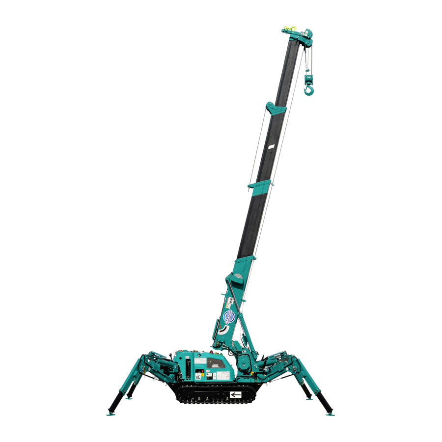
SERVICE MANUAL
MINI-CRAWLER CRANE
Serial No. G0121 and up
The parts numbers and lists written in this service manual are the
references for the services such as disassembling and assembling.
Be sure to ALWAYS refer to the latest parts catalog (the latest
information) before ordering any part, since the parts and the
model numbers are subject to change during the endless
improvements and changes of our Machine.
101E-SM1002-00
Advertisement
Table of Contents
Troubleshooting

Related Manuals for Maeda MC-174CRM


Summary of Contents for Maeda MC-174CRM
- Page 1 101E-SM1002-00 SERVICE MANUAL MINI-CRAWLER CRANE Serial No. G0121 and up The parts numbers and lists written in this service manual are the references for the services such as disassembling and assembling. Be sure to ALWAYS refer to the latest parts catalog (the latest information) before ordering any part, since the parts and the model numbers are subject to change during the endless improvements and changes of our Machine.
-
Page 3: Table Of Contents
CONTENTS ITEM Page GENERAL 1. SPECIFICATION DIMENSIONNAL DRAWING 2. DIMENSIONNAL DRAWING OF OUTRIGGER WIDTH 3. PRINCIPLE SPECIFICATION LIST 4. WORKING RADIUS LIFTING HEIGHT 5. TOTAL RATED LOAD CHART 6. STANDARD PRESSURE AND OPERATING TIME CHART 6.1 OUTRIGGER 6.2 CRANE OPERATION 6.3 TRAVELLING OPERATION 7. -
Page 4: Item Page
ITEM Page 8. TRAVELLING MOTOR 2-38 8.1 EXTERIOR VIEW AND SPECIFICATIONS 2-38 8.2 INNER PARTS 2-39 8.3 BASICS OF FUNCTIONALITY 2-40 8.4 FUNCTION 2-41 9. OUTRIGGER CONTROL VALVE 2-46 9.1 EXTERIOR VIEW AND SPECIFICATIONS 2-46 9.2 INNER PARTS 2-48 10. CRANE CONTROL VALVE 2-50 10.1 EXTERIOR VIEW 2-50... - Page 5 ITEM Page 18. OUTRIGGER SYSTEM 2-98 18.1 EXTERIOR VIEW OF No.1 OUTRIGGER 2-98 18.2 EXTERIOR VIEW OF No.2 OUTRIGGER 2-100 18.3 EXTERIOR VIEW OF No.3 OUTRIGGER 2-102 18.4 EXTERIOR VIEW OF No.4 OUTRIGGER 2-104 19.OUTRIGGER CYLINDER 2-106 19.1 EXTERIOR VIEW AND SPECIFICATIONS 2-106 19.2 INNER PARTS 2-108...
- Page 6 ITEM Page 15. CALIBRATION PROCEDURE 3-42 15.1 LIST OF ITEMS 3-42 15.2 PROCEDURE 3-43 15.3 DISPLAY DETAILS AT CALIBRATION MODE 3-51 16. TEST MODE 3-52 16.1 CALL OUT OF TEST MODE 3-52 16.2 L01 (ROM/RAM Test) 3-53 16.3 L02 (LED TEST) 3-53 16.4 L03 (Switch Test) 3-53...
-
Page 7: General
GENERAL 1. SPECIFICATION DIMENSIONAL DRAWING 2. DIMENSIONAL DRAWING OF OUTRIGGER WIDTH 3. PRINCIPLE SPECIFICATION LIST 4. WORKING RADIUS LIFTING HEIGHT 5. TOTAL RATED LOAD CHART 6. STANDARD PRESSURE AND OPERATING TIME CHART 7. POWER TRAIN DRAWING 1-10... -
Page 8: Specification Dimensionnal Drawing
1. SPECIFICATION DIMENSIONAL DRAWING... -
Page 9: Dimensionnal Drawing Of Outrigger Width
2. DIMENSIONAL DRAWING OF OUTRIGGER WIDTH... -
Page 10: Principle Specification List
3. PRINCIPLE SPECIFICATION LIST System / Item MC-174CRM Machine mass 1290kg Overall length width height 2000mm x 590mm x 1300mm Mass and Distance between idler and sprocket 1044mm dimensions Track gauge 410mm Track width 180mm Maximum total rated load ... -
Page 11: Working Radius Lifting Height
4. WORKING RADIUS AND LIFTING HEIGHT... -
Page 12: Total Rated Load Chart
5. TOTAL RATED LOAD CHART The Total rated load Chart is based on actual working radius with the bending of boom attributable to load reflected and is shown with the mass of hook block (20kg) included. [1] TOTAL RATED LOAD CHART FOR 4 FALLS Outrigger Extended to Maximum 1.83m BOOM 2.97m BOOM... - Page 13 [2] TOTAL RATED LOAD CHART FOR 2 FALLS Outrigger Extended to Maximum 1.83m BOOM 2.97m BOOM 4.21m BOOM 5.45m BOOM Working Total rated Working Total rated Working Total rated Working Total rated radius (m) load (kg) radius (m) load (kg) radius (m) load (kg) radius (m)
- Page 14 [3] TOTAL RATED LOAD CHART FOR SINGLE FALL Outrigger Extended to Maximum 1.83m BOOM 2.97m BOOM 4.21m BOOM 5.45m BOOM Working Total rated Working Total rated Working Total rated Working Total rated radius (m) load (kg) radius (m) load (kg) radius (m) load (kg) radius (m)
-
Page 15: Standard Pressure And Operating Time Chart
6. STANDARD PRESSURE AND OPERATING TIME CHART 6.1 OUTRIGGER (When Oil Temperature 30 - 50 °C) When Full Accelerating Operating Pressure (MPa) Operating time (sec) (At Travelling control valve) Extend 17.4±1 8.4±2 Front Outrigger Slide (1), (4) (1-piece) Retract 19.6±1 9.4±2 Extend 17.5±1... -
Page 16: Power Train Drawing
7. POWER TRAIN DRAWING 1-10... -
Page 17: Construction & Maintenance
CONSTRUCTION & MAINTENANCE 1. HYDRAULIC CERCUIT DIAGRAM 2. HYDRAULIC PIPING 3. HYDRAULIC OIL TANK 2-18 4. RETURN MANI-BLOCK 2-22 5. ENGINE ASSEMBLY 2-23 6. HYDRAULIC OIL PUMP 2-28 7. TRAVELLING CONTROL VALVE 2-34 8. TRAVELLING MOTOR 2-38 9. CRANE CONTROL VALVE 2-46 10. - Page 19 1. HYDRAULIC CERCUIT DIAGRAM...
-
Page 22: Crane Rotation Portion
2. HYDRAULIC OIL PIPING 2.1 CRANE ROTATE PORTION... - Page 23 Rotary Joint Connection Table Connector Hose/Piping Connector Connecting to Port Port Function Equipment Parts No. Mark Parts No. Parts No. 22611-11035 22779-83088 22611-11130 Boom lowering Derricking Cylinder 22611-11035 22779-83099 22611-11130 Boom raising (22611-11050) 22611-11050 22788-95026 Hook lowering (349-4413000) Winch Motor (22611-10150) 22611-11050 22778-95033...
-
Page 24: Crane Fixed Portion
2.2 CRANE FIXED PORTION... - Page 25 Crane Control Valve Connection Table Connector Hose/Piping Connector Connecting to Port Port Function Equipment Parts No. Mark Parts No. Parts No. 22611-11035 22781-83145 22611-11035 Boom lowering 22611-11035 22781-83150 22611-11035 Boom raising 22611-11050 22782-85145 22611-11050 Rotary Joint Hook lowering 349-441300 22782-85142 22611-11050 Hook raising S101J2062000...
-
Page 26: Travelling Line
2.3 TRAVELLING LINE 2-10... - Page 27 DESCRIPTION Q’TY NOTICE Elbow (45 deg.) 1072-06-04 Elbow (45 deg.) 1072-06-04 Travelling Hose (A) NV210-6-300L 1005=0590 Travel ling Hose (B) NV210-6-230L 1005=0590 2-11...
-
Page 28: Outrigger Line
2.4 OUTRIGGER LINE 2-12... - Page 29 Outrigger Control Valve Connection Table Connector Hose/Piping Connector Port Parts No. Parts No. Parts No. 101-3290900 101-3291000 101-3291100 101-3291200 22511-07350 350-4390100 101-4556600 101-4556700 101-4556400 101-4556500 Outrigger Cylinder Connection Table Hose/Piping Connector Connecting to Port Port Function Equipment Mark Parts No. Parts No.
-
Page 30: Pump, Tank, Drain And Pilot Line
2.5 PUMP, TANK, DRAIN AND PILOT LINE 2-14... - Page 31 Pump Line Connection Table Connector Hose Connector Connecting to Equipment Port Port Equipment Parts No. Mark Parts No. Parts No. Suction Hydraulic 101-3289200 22812-25009 (Under) Tank Pump 22611-12850 22750-A5055 22611-12356 Travelling 22611-11150 22750-A5052 22611-12356 Control Valve 22611-11160 22750-F6040 22611-11160 Outrigger Crane Control Valve 22611-12360...
- Page 32 Q’TY DESCRIPTION NOTICE Suction Elbow Parts No.: 101-3289200 Bolt M10X1.5X30L (Plating) Plane Washer M10 (Plateing) Spring Washer M10 (Plateing) φ25X28 90L Suction Hose 1X-40 (φ40 - φ30) Band Tee (With Seat) 9071-06 Elbow (90 deg. With Seat) 1071-06 Long Elbow (90 deg. With Seat) 1071-08-06-78A Elbow (90 deg.
- Page 33 2-17...
-
Page 34: Hydraulic Oil Tank
3. HYDRAULIC OIL TANK 2-18... - Page 35 Q’TY DESCRIPTION NOTICE Hydraulic Oil Tank Parts No.: 101-1143700 Return Filter Parts No.: 329-3112700 Air Breather Assembly Parts No.: 353-4453000 Suction Filter Parts No.: 359S72100000 Suction Cover- Parts No.: 359-4470700 Flange Parts No.: 359-3225800 Packing Parts No.: 359-4470800 Level Gauge Parts No.: 329-4290000 Bolt M12X1.75X25L (Plateing)
-
Page 36: Suction Filter
3.1 SUCTION FILTER Q’TY DESCRIPTION NOTICE Filter 150 mesh End Plate (A) End Plate (B) Inner Tube L= 30mm Holder Spring Specifications Model SFR-08 Filtration Precision 150 mesh Flow Capacity 90L/min 2-20... -
Page 37: Return Filter
3.2 RETURN FILTER Q’TY DESCRIPTION NOTICE Cover Inner Tube Element 30μ Plate 0.8t Valve Holder Valve Assembly Stopper Screw M5X12 Specifications Used Oil ISO VG32, 46 Flow Capacity 25L/min (Max.40L/min) Oil Temperature -20°C to 120°C 30μ Filtration Precision Filtration Area 1400cm Bypass Valve Setting Pressure 0.1MPa... -
Page 38: Return Manifold Block
4. RETURN MANIFOLD BLOCK 2-22... -
Page 39: Engine Assembly
5. ENGINE ASSEMBLY Details of the engine of structures and inspections see separate engine manual “WORKSHOP MANUAL, MITSUBISHI MEIKI ENGINE, TYPE GM SERIES”. 5.1 ENGINE SPECIFICATIONS Engine Model Mitsubishi GM401LE Type 1-cylinder, Air cooled, 4-cycle gasoline engine 1 – φ89mm x 63mm No. -
Page 40: Engine Exterior View
5.2 ENGINE EXTERIOR VIEW 2-24... - Page 41 Q’TY DESCRIPTION NOTICE Engine Assembly Parts No. S101A2426000 Engine (GM401LE-993) (MITSUBISHI) Muffler (Silent type) Muffler Gasket (t=0.2mm) Muffler Gasket (t=1.4mm) Nipple (L=50mm) Gasket (For nipple) PTO Parts Parallel Key Tool Set (Not shown) Power Unit Base Exhaust Pipe Muffler Bracket Bolt M10X 1.75 X 45L (Plating) Bolt...
-
Page 42: Each Section Name
5.3 EACH SECTION NAME 2-26... - Page 43 DESCRIPTION DESCRIPTION DESCRIPTION Cylinder Block Spark Plug Starter Crankcase Cover Valve Spring Flywheel Crankshaft Valve Stem Seal Charging Coil Camshaft Intake & Exhaust valve Bearing Blancer Shaft Rocker Arm Oil Seal Connecting Rod Pivot Nut Oil Gauge Piston Lock Nut Drain Plug Governor Shaft Cylinder Head Cover...
-
Page 44: Hydraulic Oil Pump
6. HYDRAULIC OIL PUMP 6.1 EXTERIOR VIEW AND SPECIFICATIONS Specifications Pump Capacity P1+P2: 8.6 + 8.6 cc/rev P1: 20.59 MPa Max. Oil Pressure P2: 20.59 MPa Rated 1800 min Revolution Max. 2000 min Suction Pressure -0.02 to +0.04 MPa Recommended Oil ISO VG 32, 46 Operating Oil Temperature 60°C... -
Page 45: Inner Parts
6.2 INNER PARTS Q’ty Q’ty Q’ty DESCRIPTION DESCRIPTION DESCRIPTION Body (S) Skipped No. O-ring Body (S) Washer Hex. Head Bolt shaft Retainer Skipped No. Cylinder Barrel Stopper Pin (A) Skipped No. Valve Plate Stopper Pin (B) Skipped No. Piston Skipped No. Skipped No. -
Page 46: P - Q Chart
6.3 P – Q CHART Testing Condition Remarks Recommended Oil ISO VG 32, 46 Input Torque 33.34 N•/m Oil Temperature 50±5 °C Revolution 1800 min Pump Horsepower Consumption 7.28 PS Revolution Direction Clockwise Pump Absorption Torque 28.44 N•/m 2-30... -
Page 47: Basics Of Functionality
6.4 BASICS OF FUNCTIONALITY 1. Outline Operation Principle This lightweight hydraulic pump can discharge two equal amounts of flow despite its compact size which requires only one conventional variable pump space. It provides with constant horsepower control characteristics which reduces discharge against increase of pump load to maintain constant load of the engine and to efficiently utilize its power. - Page 48 3. Constant Horsepower Variable Mechanism The pump capacity varies with the swash plate angle, and the swash plate angle allows performing constant horsepower control with the simple direct-acting variable mechanism. The center of rotation of the swash plate is at the ball on the rear side of the pump. Load F1 from the piston side is located in the direction shown in the figure and generates a right-turn moment to the swash plate.
-
Page 49: Trouble Shooting
6.5 TROUBLE SHOOTING Disorders Cause Counter-action • Engine revolution rate is higher than the • Adjust to prescribed rate. prescription. • Adjust to prescribed rate. Engine, Over load • Pressure is higher than the prescription. • Repair or replace • Pump components, seizure or damage. Hydraulic oil discharge amount is •... -
Page 50: Travelling Control Valve
7. TRAVELLING CONTROL VALVE 7.1 EXTERIOR VIEW AND SPECIFICATIONS Each Ports Connection Each Ports Connection Port Size Port Size Pump P2 Port PF1/2 Right Travelling Motor B Port (Forward) PF3/8 Pump P1 Port PF1/2 Right Travelling Motor A Port (Reverse) PF3/8 Return PF1/2... -
Page 51: Inner Parts
7.2 INNER PARTS Q’TY Q’TY Q’TY DESCRIPTION DESCRIPTION DESCRIPTION Compression Spring Wire Screw (M5 X 12) Needle Valve Spring Cover Set Screw (M10 X 14) Cap Nut Tie Rod Nut (M8) Gasket Inlet Housing Rivet Spring Holder Inlet Housing O-Ring (1A-P12) Compression Spring Plug O-Ring (1B-P9) -
Page 52: Inspection And Adjustment
7.3 INSPECTION AND ADJUSTMENT [1] PARTS INSPECTION Assembly Criteria Counter-action • Scratch, rust and/or corrosion in spool sliding area. • Replace • Scratch, rust and/or corrosion in seal pocket of spool insertion. • Replace • Housing • Scratch, rust and/or corrosion in port seal area next to O-ring. •... -
Page 53: Trouble Shooting
7.4 TROUBLE SHOOTING Each Item shown in the table below indicates only individual problem, however, troubles may be caused by multiple problems, in many cases. It is advisable to check one by one for efficient trouble shooting. Disorders Cause Counter-action •... -
Page 54: Travelling Motor
8. TRAVELLING MOTOR 8.1 EXTERIOR VIEW AND SPECIFICATIONS Right Travelling Motor Left Travelling Motor A Port Reverse B Port Reverse B Port Forward A Port Forward Specifications Specifications of Reduction Gear Max. Output Torque 978.5 N•m (99.8 kgf•m) Capacity 351.1/173.7 cm /rev Max. -
Page 55: Inner Parts
8.2 INNER PARTS 2-39... -
Page 56: Basics Of Functionality
8.3 BASICS OF FUNCTIONALITY 2-40... -
Page 57: Function
8.4 FUNCTION PHV-series Travelling motor consists of the fixed body mainly composed of a hydraulic motor and a hydraulic valve and the rotating body mainly composed of a simple planetary reduction gear. 8.4.1 REDUCTION GEAR [1] FUNCTION Travelling motor reduction gear is composed of 2 stages of simple planets, reduces the speed of high-speed rotary motion from the hydraulic motor, converts it into low-speed large torque and rotates the case. - Page 58 8.4.2 HYDRAULIC MOTOR [1] FUNCTION The hydraulic motor is of an axial piston motor type (rotating cylinder swash plate type) and converts hydraulic energy from the pump into rotary motion. [2] STRUCTURE AND BASICS OF FUNCTIONALITY (See the figure below.) The pressurized oil flown in from the hydraulic valve is supplied to the valve plate (5).
- Page 59 [3] BASICS OF FUNCTIONALITY OF 2-SPEED MOTOR Swash plate has two sides “ I ” and “ II ” on the opposite from the side shoe frictions, and is supported by two balls fixed on body. The balls are fixed eccentrically to the axis line, so when the speed set to low, side “ I ” is pushed on to body 2 by hydraulic power on piston and spring power in cylinder barrel, making swash plate angle α, capacity maximum.
- Page 60 8.4.3 HYDRAULIC VALVE (CONTER BALANCE VALVE) The pressurized oil, when supplied from Port A, pushes to open the check valve (3) and flows in the inlet side port A’ of the hydraulic motor. The pressurized oil flows through the choke hole C, enters the chamber D, overwhelms the spring (4) and slides the spool (2) to the right.
- Page 61 8.4.4 PARKING BRAKE Parking brake works to fix hydraulic motor inlet axis mechanically, when travelling motor is at halt. [1] PARKING BRAKE AT WORK When pressurized oil is not supplied to A or B port, brake piston (1) is pushed to the direction of the arrow shown in Fig. 8 by spring (2).
-
Page 62: Outrigger Control Valve
9. OUTRIGGER CONTROL VALVE 9.1 EXTERIOR VIEW AND SPECIFICATIONS Each Ports Connection Each Ports Connection Port Size Port Size Confluence Selector Solenoid Valve A Port PF1/2 Outrigger 1 Solenoid Valve P1 Port (Out) PF3/8 Return PF1/2 Outrigger 1 Solenoid Valve P2 Port (In) PF3/8 Outrigger 3 Solenoid Valve P1 Port (Out) PF3/8... - Page 63 Circuit Diagram Valve Rated Specifications Common Use Pressure 20.6 MPa (210 kgf/cm Rated Flow Capacity 50 Littre/min Relief Setting Pressure 2.94 to 24.5 MPa (30 to 250 kgf/cm Sequence Valve Setting Pressure 1.27 to 1.67 MPa (13 to 17 kgf/cm Pressure Reducing Valve Setting Pressure 1.18 to 1.57 MPa (12 to 16 kgf/cm T Port Allowable Back Pressure...
-
Page 64: Inner Parts
9.2 INNER PARTS 2-48... - Page 65 Tightening Torque Table Section Thread Size Tightening Torque (N•m) Assembly Bolt 19.6±0.98 18.6±0.98 Coat the LOCKTIGHT #242 Spool End, Connecting End Solenoid Assembly Bolt 2.45 to 3.43 Socket Head Bolt 9.81 to 10.8 PF1/4 24.5 to 29.4 PF3/8 39.2 to 49.0 Accelerator Valve, Plug 39.2 to 49.0 58.8 to 68.6...
-
Page 66: Crane Control Valve
10. CRANE CONTROL VALVE 10.1 EXTERIOR VIEW Each Ports Connection Each Ports Connection Port Size Port Size Travelling Control Valve (CO1) PF1/2 Return PF1/2 Derricking Cylinder Head (Boom Lowering) PF3/8 Telescoping cylinder Bottom (Boom Extending) PF3/8 Derricking Cylinder Bottom (Boom Raising) PF3/8 Telescoping cylinder Head (Boom Retracting) PF3/8... -
Page 67: Outline
10.2 OUTLINE Valve Rated Specifications Max. Operating Pressure 20.6 MPa (210 kgf/cm Rated Flow Capacity 50 Littre/min Sequence Valve Setting Pressure 1.27 to 1.67 MPa (13 to 17 kgf/cm Reducing Pressure Valve Setting Pressure 1.42 to 1.47 MPa (14.5 to 15.0 kgf/cm Operating Oil Temperature Range -20 to 80 °C Recommended Hydraulic Oil Viscosity Range... -
Page 68: Hydraulic Circuit Diagram
10.3 HYDRAULIC CIRCUIT DIAGRAM [Circuit Configuration] Since the solenoid selector valve (Derrick, winch, Telescopic and slewing) is composed of parallel circuits, more than one solenoid selector valve can be operated at the same time. In case of simultaneous operation, the actuator with the lowest load pressure starts operating first. -
Page 69: Function Of Each Section
10.4 FUNCTION OF EACH SECTION [1] COMPOSITION AND FUNCTION OF SUPPLY SECTION 1. Sequence Valve 2. Pressure Reducing Valve The figure is simplified to show the circuit configuration. The supply section is composed of the supply port (a) to which pressurized oil is supplied from the pump, the oil line through which the pressurized oil flows to the controller (selector), the outlet port (b) through which return oil from the actuator flows to the tank, the sequence valve (1) and the pressure reducing valve (2). - Page 70 [2] FUNCTION OF FLOW CONTROL VALVE 1. When each selector valve is at the neutral position Pressurized oil from the pump flows through the center bypass lines of the control valve and of each selector valve and the tank line and returns to the tank from the outlet port of the supply section. 2-54...
- Page 71 2. When selector valves are operated (When the negative solenoid proportional pressure reducing valve solenoid is not energized) 1. Detection Valve 4. Secondary Side Piston B 2. Flow Control Spool 5. Negative Solenoid Proportional Pressure Reducing Valve 3. Primary Side Piston A When any selector valve is changed over, the center bypass line is closed, and pressurized oil pushes up the detection valve (1) and flows in the parallel line.
- Page 72 3. When the selector valves are operated (When the negative solenoid proportional pressure reducing valve solenoid is energized) 1. Detection Valve 2. Flow Control Spool 5. Negative Solenoid Proportional Pressure Reducing Valve Coil Current VS pilot Secondary Pressure Coil Current VS Parallel Line Flow When a current is applied to the negative solenoid proportional pressure reducing valve (5) solenoid (SOL11), the secondary pressure changes (drops) according to the current value and the leftward force, which affects the flow control spool (2), also reduces.
- Page 73 [3] FUNCTION OF ACCELERATOR POSITIONER When a current is applied to the solenoid (SOL12), the final controlling element moves the spool (2) by the input current, changes the engine speed with the connected accelerator wire and controls the discharge flow from the pump. 1.
- Page 74 [4] FUNCTION OF SOLENOID SELECTOR VALVE (Derricking, Winch, Telescoping and Slewing) 1. When the solenoid is not energized 1. Spool 4. Pilot Valve Spring 2. Return Spring 5. Socket 3. Pilot Valve The return spring (2) retains the spool (1) at the neutral position. The pilot valve spring (4) has pushed up the pilot valve (3) to the solenoid side.
- Page 75 2. When the solenoids (SOL1 to 8) were energized 1. Spool 4. Pilot Valve Spring 7. Pilot Piston 2. Return Spring 5. Socket 8. Filter 3. Pilot Valve 6. Push Pin The following explanation is based on the state that the right solenoid was energized. The push pin (6) pushes down the right pilot valve (3), and the pilot chamber (b) is connected to the pilot line through the filter (8) and the pilot pressure is supplied to the chamber.
- Page 76 [5] FUNCTION OF PRESSURE REDUCING VALVE 1. When the secondary pressure is below the set value Since the pressure reducing valve spool (1) pressed with the pressure reducing valve spring (2), the pressurized oil of the primary pressure flows to the secondary side of the pressure reducing valve spool (1) line (a).
-
Page 77: Trouble Shooting
10.5 TROUBLE SHOOTING Disorders Cause Counter-action • The mounting bolts does not tighten with the • Check the torque value The pressure does not reach the specified tightening torque. • Being unloaded without full stroke. • See “The solenoid selector valve does not specified pressure. -
Page 78: Travelling Speed Selector Valve
11. TRAVELLING SPEED SELECTOR VALVE 11.1 EXTERIOR VIEW AND SPECIFICATIONS Each Ports Connection Port Size Travelling Control Valve Pressure Gauge Port PF1/4 Left and Right Travelling Motor PP Port PF1/4 Drain PF1/4 Q’TY Q’TY Q’TY DESCRIPTION DESCRIPTION DESCRIPTION Plug Solenoid Rivet Body Name Plate... -
Page 79: Inspection And Adjustment
11.2 INSPECTION AND ADJUSTMENT [1] PARTS INSPECTION Assembly Criteria Counter-action • Damage to solenoids, including short-circuit and wire breakage. • Replace • Coil Assembly • Short-circuit and wire breakage. • Replace • Scratch, rust and/or corrosion in spool sliding area. •... -
Page 80: Rotary Joint
12. ROTARY JOINT 12.1 EXTERIOR VIEW AND SPECIFICATIONS 2-64... - Page 81 Q’TY DESCRIPTION NOTICE Rotary Joint Slip Ring Assembly Bolt M10X1.5X25L (Plating) 109T Spring Washer M10 (Plating) Rotary Joint Connection Table Thread Thread Stamp Upper Side Connecting Hose Stamp Lower Side Connecting Hose Size Size WA Hose (Winch Motor Port A) PF3/8 WA Hose (Crane Control Valve Port B2) PF3/8...
-
Page 82: Inner Parts
12.2 INNER PARTS 2-66... - Page 83 DESCRIPTION Q’TY DESCRIPTION Q’TY DESCRIPTION Q’TY Slipper Seal Name Plate Rivet Plate Skipped No. O-Ring (1B-P10) Hex. Socket Head Bolt (M6X16) O-Ring (1B-G65) Shaft Hex. Socket Head Bolt (M8X70) O-Ring (AS568-229) Body Hex. Socket Head Bolt (M10X18) Hex. Socket Head Bolt (PT1/8) Flange Plane Washer (M6) Slip Ring...
-
Page 84: Hook Block
13. HOOK BLOCK 2-68... - Page 85 DESCRIPTION Q’TY NOTICE Block Plate Bracket Sheave Pin Sheave Hook Hook Nut Sheave Collar Weight Wire Rope Latch Wire Rope Latch Spring Thrust Bearing #51206 Thrust Bearing 5 X 45L Cotter Pin 2X12L (Plating) Bolt M8X15L (Plating) 10.9t Plane Washer M6 (Plating) Spring Washer M8 (Plating)
-
Page 86: Hook Block Inspection
13.1 HOOK BLOCK INSPECTION The hook block is one of the important maintenance parts. Check by the following procedure and be sure to always use under safe condition. Repair or replace immediately whenever any defect is found as result of the inspection. Replacement requires a modification inspection prior. - Page 87 2-71...
-
Page 88: Boom System
14. BOOM SYSTEM 2-72... - Page 89 Q’TY DESCRIPTION NOTICE No.1 Boom No.2 Boom No.3 Boom No.4 Boom Wire Rope Sheave Derricking Cylinder Pin End Plate Wire Rope (For Boom Extending) Wire Rope (For Boom Retracting) Wire Clip Assembly Slide Plate (Boom Bottom) Slide Plate (BD3 Bottom) Slide Plate (BD2 Upper) Slide Plate (BD3 Upper) Sheave (For Boom Extending)
- Page 90 Q’TY DESCRIPTION NOTICE Bolt M10X1.5X14L (Plating) 10.9T Button Bolt (With Hex. Hole) M10X1.5X16L (Plating) 8.8T Bolt M10X1.5X20L (Plating) 8.8T Bolt M10X1.5X20L (Plating) 10.9T Flat Head Bolt (With Hex. Hole) M6X1.0X10L Socket Head Screw M10X1.5X30L Socket Head Screw M10X1.5X40L M10X1.5 (Plating) M12X1.75 (Plating) Spring Washer M6 (Plating)
- Page 91 2-75...
-
Page 92: Telescoping And Derricking Cylinder
15. TELESCOPING AND DERRICKING CYLINDER 15.1 TELESCOPING CYLINDER 2-76... - Page 93 Q’TY DESCRIPTION NOTICE Cylinder (No.1 Cylinder) Piston Rod (No.1 Cylinder) Cylinder Head (No.1 Cylinder) Bushing (No.1 Cylinder) LFB-4020 Stopper (No.1 Cylinder) Rod Packing (No.1 Cylinder) Dust Seal (No.1 Cylinder) O-RING (No.1 Cylinder) 1B-P50A Piston (No.1 Cylinder) Sleeve (No.1 Cylinder) Piston Packing (No.1 Cylinder) O-RING (No.1 Cylinder) 1B-P24 Back-up Ring (No.1 Cylinder)
- Page 94 Q’TY DESCRIPTION NOTICE • Set Screw (No.2 Cylinder) M6X6L Tightening Torque: 9.8 N m (Coat the LOCKTIGHT #262) O-RING (No.1 Cylinder) 1B-P12 • Socket Head Bolt M12X75L Tightening Torque: 107.9 N • Counter Balance Valve Part No.: 300S09200000 Tightening Torque: 88.2 to 98.1 N •...
-
Page 95: Telescoping Cylinder Hydraulic Circuit System
15.2 TELESCOPING CYLINDER HYDRAULIC CIRCUIT SYSTEM 2-79... -
Page 96: Counter Balance Valve (For Telescoping And Derricking Cylinder)
15.3 COUNTER BALANCE VALVE (FOR TELESCOPING AND DERRICKING CYLINDER) Specifications Max. Common Use Pressure 20.6 MPa (210 kgf/cm Resiting Pressure 30.9 MPa (315 kgf/cm Max. Flow Capacity 50 L/min Rated Flow Capacity 40 L/min Allowable Leakage Capacity Less than 0.05 L/min (Apply 20.6 MPa [210 kgf/cm ] From Port B) +0.3 Pilot Pressure... - Page 97 15.3.2 FUNCTION 1. When Neutral 2. When Extending 3. When Retracting 2-81...
-
Page 98: Sequence Valve (For Telescoping Cylinder)
15.4 SEQUENCE VALVE (FOR TELESCOPING CYLINDER) Specifications Rated Flow Capacity 40 L/min Allowable Leakage Capacity Less than 0.05 cc/min [Apply 20.6 MPa (210 kgf/cm From Port B] +0.3 Pilot Pressure 1.18 MPa (12 kgf/cm ) At Valve Opened Check Valve Cracking Pressure 2.45 MPa (25 kgf/cm Operating Force 0.65 x Pressure + 20 kg... -
Page 99: Mechanical Check Valve (For Telescoping Cylinder)
15.5 MECHANICAL CHECK VALVE (FOR TELESCOPING CYLINDER) Specifications Rated Flow Capacity 50 L/min +0.3 Pilot Pressure 1.18 MPa (12 kgf/cm ) At Valve Opened Pressure Loss (B to A) Less than 9.8 MPa (100 kgf/cm Check Valve Cracking Pressure 0.098 MPa (1 kgf/cm 2-83... -
Page 100: Left Side Derricking Cylinder
15.6 LEFT SIDE DERRICKING CYLINDER 2-84... - Page 101 Q’TY DESCRIPTION NOTICE Cylinder Piston Rod Cylinder Head Bushing LFB-3525 Rod Packing GNY-35 Back-up Ring 35,45,1.5 Dust Seal SCB-35 Snap Ring AR48 O-RING 1B-G55 Back-up Ring T3-G55 O-RING 1B-G60 Piston Piston Ring GPY-55 Back-up Ring 45,55,1.5 Wear Ring 55,49,12 U-ring Holder O-RING 1B-P21 U-nut...
-
Page 102: Right Side Derricking Cylinder
15.7 RIGHT SIDE DERRICKING CYLINDER 2-86... - Page 103 Q’TY DESCRIPTION NOTICE Cylinder Piston Rod Cylinder Head Bushing LFB-3525 Rod Packing GNY-35 Back-up Ring 35,45,1.5 Dust Seal SCB-35 Snap Ring AR48 O-RING 1B-G55 Back-up Ring T3-G55 O-RING 1B-G60 Piston Piston Ring GPY-55 Back-up Ring 45,55,1.5 Wear Ring 55,49,12 U-ring Holder O-RING 1B-P21 U-nut...
-
Page 104: Winch System
16. WINCH SYSTEM 16.1 EXTERIOR VIEW OF WINCH UNIT 2-88... - Page 105 Q’TY DESCRIPTION NOTICE Drum (With Groove) Wedge Drum Shaft Fiwed Plate Staffing Winch Gear Cover Gear (BY20) Mechanical Brake Hydraulic Motor • Connector PT3/8 Tightening Torque: 49 to 78 N Connector • Adapter (With Check) Tightening Torque: 49 to 78 N Connector Elbow Bearing...
-
Page 106: Mechanical Brake Inner Paerts And Specifications
16.2 MECHANICAL BRAKE INNER PAERTS AND SPECIFICATIONS 2-90... - Page 107 Q’TY DESCRIPTION NOTICE Case Cover Spring Parallel Pin 8x30 Gear (1) Gear (2) Gear Shaft Bushing Name Plate Latchet Wheel Brake Disc Shim Disc Retainer Disc Assembly Shaft Latch Collar Collar Packing Roller Bearing #6208 Roller Bearing #6007 Roller Bearing #6006 Roller Bearing #6003...
-
Page 108: Exterior View And Specifications Of Winch Motor
16.3 EXTERIOR VIEW AND SPECIFICATIONS OF WINCH MOTOR Specifications Capacity per Stroke 14.5 cm /rev Rated Pressure 20.6 MPa (210 kgf/cm Sage Pressure 24.5 MPa (250 kgf/cm Max. Output Revolution 3000 min Common Less than 0.1 MPa (1 kgf/cm Drain Circuit Pressure Peak Less than 0.3 MPa (3 kgf/cm... - Page 109 2-93...
-
Page 110: Slewing System
17. SLEWING SYSTEM 17.1 EXTERIOR VIEW 2-94... - Page 111 Q’TY DESCRIPTION NOTICE Slewing Bearing Grease Nipple A-PT1/8 Slewing Gear Box Assembly Hydraulic Oil Motor Slewing Gear Cover (A) Slewing Gear Cover (B) Slewing Gear Cover (C) • Bolt M12X1.75X40L Tightening Torque: 92.6 to 125.5 N m (Coat the LOCKTIGHT #262) •...
-
Page 112: Slewing Reduction Gear
17.2 SLEWING REDUCTION GEAR Q’TY DESCRIPTION NOTICE Gear Box Pinion Shaft Worm wheel Worm Shaft Cover Bearing Retainer Taper Roller Bearing #32006 Roller Bearing #63132 Roller Bearing #6006 Oil Seal LSRD 406211 Bolt M8X16 Socket Head Bolt M6X16 Spring Washer Spring Washer Oil Gauge D.M. -
Page 113: Slewing Motor Exterior View And Specifications
17.3 SLEWING MOTOR EXTERIOR VIEW AND SPECIFICATIONS Slewing Motor Port A Clockwise Port B Counterclockwise Specifications Model J-32EBE-B Capacity per Stroke 31.6 cc/rev Rated revolution 661 min Rated Torque 39 N•m (4.0 kgf•m) Max. Torque 49 N•m (5.0 kgf•m) Rated Pressure 9.3 MPa (95 kgf/cm Max. -
Page 114: Outrigger System
18. OUTRIGGER SYSTEM 18.1 EXTERIOR VIEW OF No.1 OUTRIGGER 2-98... - Page 115 Q’TY DESCRIPTION NOTICE Rotary Rotary Shaft Outrigger Base Outrigger Top Inner Box Rigger Adapter Outrigger Base and Top Connecting Pin Outrigger Cylinder Bottom Pin Rigger Adapter Connecting Pin Position Pin Position Pin Position Pin Stay Dumper Inner BoxStopper End Plate End Plate Dumper Pin Snap Pin (1)
-
Page 116: Exterior View Of No.2 Outrigger
18.2 EXTERIOR VIEW OF No.2 OUTRIGGER 2-100... - Page 117 Q’TY DESCRIPTION NOTICE Rotary Rotary Shaft Outrigger Base Outrigger Top Inner Box Rigger Adapter Outrigger Base and Top Connecting Pin Outrigger Cylinder Bottom Pin Rigger Adapter Connecting Pin Position Pin Position Pin Position Pin Stay Dumper Inner BoxStopper End Plate End Plate Dumper Pin Snap Pin (1)
-
Page 118: Exterior View Of No.3 Outrigger
18.3 EXTERIOR VIEW OF No.3 OUTRIGGER 2-102... - Page 119 Q’TY DESCRIPTION NOTICE Rotary Rotary Shaft Outrigger Base Outrigger Top Inner Box Rigger Adapter Outrigger Base and Top Connecting Pin Outrigger Cylinder Bottom Pin Rigger Adapter Connecting Pin Position Pin Position Pin Position Pin Stay Dumper Inner BoxStopper End Plate End Plate Dumper Pin Snap Pin (1)
-
Page 120: Exterior View Of No.4 Outrigger
18.4 EXTERIOR VIEW OF No.4 OUTRIGGER 2-104... - Page 121 Q’TY DESCRIPTION NOTICE Rotary Rotary Shaft Outrigger Base Outrigger Top Inner Box Rigger Adapter Outrigger Base and Top Connecting Pin Outrigger Cylinder Bottom Pin Rigger Adapter Connecting Pin Position Pin Position Pin Position Pin Stay Dumper Inner BoxStopper End Plate End Plate Dumper Pin Snap Pin (1)
-
Page 122: Outrigger Cylinder
19. OUTRIGGER CYLINDER 19.1 EXTERIOR VIEW AND SPECIFICATIONS 2-106... - Page 123 Q’TY DESCRIPTION NOTICE Outrigger Cylinder 1-17 Double Pilot Check Valve • Rod Guide Cover Tightening Torque: 294 N Outrigger Cover Bolt M8X1.25X16L (Plating) Spring Washer M8 (Plating) Plane Washer M8 (Plating) Specifications Cylinder Bore x Rod O.D. - Stroke 70 mm X 35 mm - 313 mm When extending 79.2 kN ( 20.6 MPa) [8.0 ton (At 210 kgf/cm...
-
Page 124: Inner Parts
19.2 INNER PARTS 2-108... - Page 125 Q’TY DESCRIPTION NOTICE Cylinder Tube Assembly Piston Rod Assembly • Cylinder Head Tightening Torque: 294 N Bushing LFB-3525 Rod Packing GNY-35 Back-up Ring 35,45,1.5 Dust Seal SCB-35 Snap Ring AR48 O-RING 1B-G65 Back-up Ring T3-G65 O-RING 1B-G70 • Piston Tightening Torque: 392.3 N Piston Ring SPGW 70 Wear Ring...
-
Page 126: Double Pilot Check Valve
19.3 DOUBLE PILOT CHECK VALVE Specifications Rated Pressure 20.6 MPa (210 kgf/cm Resisting Pressure 41.2 MPa (420 kgf/cm Max. Flow Capacity 10 L/min Allowable Leakage Level Less than 0.05 L/min (Apply 17.2 MPa [175 kgf/cm ] From Port A2 and B2) Check Valve Cracking Pressure 0.49 MPa (5 kgf/cm Pilot Area Ratio... - Page 127 2-111...
-
Page 128: Assembly And Disassembly Of Boom
20. ASSEMBLY AND DISASSEMBLY OF BOOM 2-112... - Page 129 [Procedure for Overhaul] 1. Start engine and lower hook block (1) to the ground. Winch wire rope should be properly slack. Take care not to cause random wound caused by over unwinding. 2. Stop engine. Unscrew bolt (2) (M8 X 15L), remove spring washer (3) and end plate (4), and take off wedge socket (5). 3.
- Page 130 11. Unscrew 2 bolts (24) (M6 X 12L), and take off boom tail cover (25). 12. Unscrew 3 bolts (26) (M6 X 12L), and take off boom head cover (27). 13. Unscrew 4 bolts (28) (M6 X 12L), and take off sheave cover (29). 14.
- Page 131 20. Remove 2 lock nuts (42) (M12), then remove 2 spherical surface nuts (43) (M10) from the tips of boom extention wire (44), and pull out the extention wire (44) from No.2 boom. 21. Unscrew 4 bolts (45) (M10 X 16L), and remove 4 spring washers (46), then take off 2 stopper plates (47). 22.
- Page 132 26. Unscrew 4 bolts (57) (M10 X 16L), and remove 4 spring washers (58), then take off 2 stopper plates (59). 27. Unscrew 4 hexagonal bolts (61) (M6 X 12L), and remove 4 spring washers (62) on both left and right side, then remove 2 side plate stopper plates (63) and side slide plates (64) respectively, on both left and right side.
- Page 133 30. Remove 4 hexagonal nuts (67) (M10) from wire tips, and remove boom retraction wire (68) from No.4 boom. 31. Pull out telescoping cylinder (69) and boom retraction wire (68) assembled together out of No.4 boom. 32. Remove boom retraction wire (44) from No.4 boom. Flatten 2 bended plates (70) on No.4 boom when removing this retraction wire (44).
- Page 134 2-118...
-
Page 135: Electric Circuit Diagram
Note: A version of this electrical circuit diagram enlarged to A2 size is prepared as an appendix. Refer to the separate A2 size circuit diagram for details. 21. ELECTRIC CIRCUIT DIAGRAM 2-119... -
Page 136: Electric System Drawing
22. ELECTRIC SYSTEM DRAWING 2-120... - Page 137 Q’TY Q’TY DESCRIPTION NOTICE DESCRIPTION NOTICE Connector Bracket (LF) Translation Cable Assembly (For remote Control) Bolt M8X1.25X20L (Plating) 4.8T Translation Cable Assembly (For remote Control) Spring Washer M8 (Plating) Engine Ground Cable L=170 Plane Washer M8 (Plating) Battery Cable (+) L=800 Connector Bracket (RF) Battery Cable (-)
- Page 138 2-122...
-
Page 139: Moment Limiter
MOMENT LIMITER 1. MOMENT LIMITER PARTS 3- 2 2. MOMENT LIMITER OVERVIEW AND FEATURES 3-25 3. EXTERNAL VIEW OF MOMENT LIMITER 3-26 4. BLOCK DIAGRAM 3-28 5. CONNECTOR DIAGRAM 3-29 6. CONNECTOR PIN ASSIGNMENT 3-30 7. INPUT/OUTPUT 3-32 8. DISPLAYS 3-34 9. -
Page 140: Moment Limiter Parts
1. MOMENT LIMITER PARTS 1.1 DISPLAY UNIT AND CONVERTER... - Page 141 DESCRIPTION Q’TY NOTICE Moment Limiter Display Moment Limiter Converter Screw (With Washer) M4X0.7X10L (Plating) Clamp RS-8000 Moment Limiter Converter Cover...
-
Page 142: Outrigger Position Detector
1.2 OUTRIGGER POSITION DETECTOR... - Page 143 DESCRIPTION Q’TY NOTICE Limit Switch Bracket 1 Limit Switch Bracket 2 Limit Switch Bracket 3 Limit Switch Bracket 4 Limit Switch Mounting Plate Limit Switch 1 Limit Switch 2 Limit Switch 3 Bolt M8X1.25X16L (Plating) Spring Washer M8 (Plating) Plane Washer M8 (Plating) Screw (With Washer) M4X12L (Plating)
-
Page 144: Outrigger Opening Detector
1.3 OUTRIGGER OPENING DETECTOR... - Page 145 DESCRIPTION Q’TY NOTICE Switch Bracket Proximity Switch Bolt M6X1.0X12L (Plating) Spring Washer M6 (Plating) Connector Cover M6X6L (Plating) Bolt M6X1.0X35L (Plating) Spring Washer M6 (Plating)
-
Page 146: Outrigger Extending Detector
1.4 OUTRIGGER EXTENDING DETECTOR... - Page 147 DESCRIPTION Q’TY NOTICE Cover (A) Cover (B) Limit Switch Bolt M6X1.0X12L (Plating) Spring Washer M6 (Plating) Bolt M5X0.8X16L (Plating) Spring Washer M5 (Plating)
-
Page 148: Boom State Detector
1.5 BOOM STATE DETECTOR 3-10... - Page 149 DESCRIPTION Q’TY NOTICE Seat Plate Length Sensor Angle Sensor Limit Switch Length Sensor Bracket Connector Cover (A) Bolt M6X1.0X16L (Plating) Spring Washer M6 (Plating) Socket Head Bolt M5X0.8X16L Spring Washer M5 (Plating) Bolt M6X1.0X35L (Plating) Spring Washer M6 (Plating) Bolt M6X1.0X14L (Plating) M6X1.0 (Plating) Spring Washer...
- Page 150 1.5.1 ANGLE SENSOR 3-12...
- Page 151 Specifications 110°, min. Inclination Angle (98°, min. to plus range and 12°, min. to minus range, based on 0°of the chart above.) Total Accuracy ±1% under vibrating conditions (Including linearity and hysteresis). Approx. 1 second at Inclination angle 90° Response (Adequate under operation temperature conditions) Potentiometer (CP-2 or equivalent) Significant Electrical Angle...
- Page 152 1.5.2 LENGTH SENSOR 3-14...
- Page 153 Q’ty Description Remarks Base Plate Case Drum Assembly Contact Cylinder Assembly Contact Assembly Potentiometer Case Packing O-ring Bracket Potentiometer NIPOSEAL, Seal Connector Gear Fasten Terminal (male) Sleeve Fasten Terminal (female) Sleeve Cable Guide Microphone Code Assembly Super lock Cable Stopper Caution Label 3-15...
-
Page 154: Load Detector
1.6 LOAD DETECTOR DESCRIPTION Q’TY NOTICE Pressure Sensor Cover Bracket Bolt M8X1.25X14L (Plating) Spring Washer M8 (Plating) Pressure Sensor Cover Bolt M6X1.0X12L (Plating) Spring Washer M6 (Plating) Connector Cover (B) Bolt M6X1.0X35L (Plating) Spring Washer M6 (Plating) 3-16... - Page 155 1. 6.1 PRESSURE SENSORS Specifications/Capacity Working range 0 to 35 MPa Permissible pressure 52.5 MPa Power Supply Voltage 12V DC ±10% Power Form 1 to 5 DC 3 wires Load Resistance 10 K-ohm, min. ±1.0 % F.S. Accuracy (Including linearity, hysteresis and repeatability at 23±2°C) Temperature ±0.1%F.S./ °C...
-
Page 156: Moment Limiter Accessory
1.7 MOMENT LIMITER ACCESSORY 3-18... - Page 157 DESCRIPTION Q’TY NOTICE Moment Limiter Display Bracket Bolt M8X1.25X14L (Plating) Spring Washer M8 (Plating) Plane Washer M8 (Plating) Moment Limiter Display Cover Bolt M6X1.0X16L (Plating) Spring Washer M6 (Plating) Plane Washer M6 (Plating) Moment Limiter Display Cover Bolt M5X0.8X20L (Plating) Spring Washer M5 (Plating) Plane Washer...
-
Page 158: Over Un-Winding Detector
1.8 OVER UN-WINDING DETECTOR 3-20... - Page 159 DESCRIPTION Q’TY NOTICE Roller Arm Axle Drive Arm Base Limit Switch Cover Roller Roller Shaft Bearing Spacer Spacer (1) Spacer (2) Bushing Limit Switch Expanding Spring Ball Bearing #6001ZZ Bushing Parallel Key 5X5X16L Bolt M8X1.25X25L (Plating) Bolt (With Washer) M6X1.0X12L (Plating) Socket Head Bolt M5X0.8X20L (Plating) Nylon Nut...
-
Page 160: Over Hoisting Stop System
1.9 OVER HOISTING STOP SYSTEM 3-22... - Page 161 DESCRIPTION Q’TY NOTICE Protect Weight Protective Rope Ring Over Hoist Detector Switch No. skipped No. skipped Limit Switch Bracket No. skipped No. skipped Limit Switch Assembly Socket Head Bolt M5X0.8X16L (Plating) No. skipped Bolt M6X1.0X20L (Plating) No. skipped No. skipped M6X1.0 (Plating) Spring Washer M6 (Plating)
- Page 162 1.9.1 OPERATION PRINCIPLE When the hook is raised too much, the weight hoisted through the wire rope is pushed up by the hook, and activates the over hoist detector switch. The contact of the over hoist detector switch opens, and the signal thereof enters the moment limiter computer, and causes the hook raising and boom extending operations to stop.
-
Page 163: Moment Limiter Overview And Features
2. MOMENT LIMITER OVERVIEW AND FEATURES Items MC-174C Type of Moment Limiter Automatic Cut Out Crane Rated Load 0 to 1.72 ton [Pressure Range: 0 to 20.6 MPa (0 to 210kg/cm DC 12V (DC 10V – 15V) Power Supply Display Panel 0.8 A (at DC 12V) Max. -
Page 164: External View Of Moment Limiter
3. EXTERNAL VIEW OF MOMENT LIMITER 3.1 DISPLAY UNIT 3-26... -
Page 165: Converter
3.2 CONVERTER 3-27... -
Page 166: System Diagram
4. SYSTEM DIAGRAM 3-28... -
Page 167: Connector Diagram
5. CONNECTOR DIAGRAM 3-29... -
Page 168: Connector Pin Assignment
6. CONNECTOR PIN ASSIGNMENT The Converter has two connectors and the Display Unit has two connectors. Pin assignment of each connector are as listed below: 6.1 CONVERTER CONNECTORS [1] POWER CONTROL CONNECTOR Model: RM15WTR-8P (HIROSE in Japan) [Corresponding Plug (Harness side): RM15WTP-8S-0 (HIROSE in Japan)] Pin No. -
Page 169: Display Unit Connectors
6.2 DISPLAY UNIT CONNECTORS [1] POWER CONTROL CONNECTOR [Corresponding Plug (Harness side): RM15WTP-8S-0 (HIROSE in Japan)] Pin No. Signal Moment ratio 4 – 20 mA output (+) Moment ratio 4 – 20 mA output (-) Over Un-winding output (Optional) Not used Not used Serial Communication output +12V... -
Page 170: Input/Output
7. INPUT/OUTPUT 7.1 CONVERTER Q’ty Direction Description Specifications 2 Pressure Sensor 1 Analog input [1 to 2.35V / 0 to 20.6 MPa (0 to 210 kgf/cm 2 Pressure Sensor 2 Analog input [1 to 2.35V / 0 to 20.6 MPa (0 to 210 kgf/cm Angle Sensor Analog input (1.8 to 4.619V / 0 to 80°) Length Sensor... - Page 171 Note 1: Photo Coupler input Note 2: Voltage output Note 3: Relay output (別紙参照 ) Note 4: Open Collector output (別紙参照 ) 3-33...
-
Page 172: Displays
8. DISPLAYS 3-34... - Page 173 Item Type Remarks Actual Load 7 Segments Permanent Indication (Letter height 10mm) Total rated load 7 Segments Permanent Indication (Letter height 8mm) Working Radius 7 Segments Permanent Indication (Letter height 10mm) Lifting Height 7 Segments Permanent Indication (Letter height 8mm) Boom Angle 7 Segments Permanent Indication (Letter height 8mm)
-
Page 174: Switches
9. SWITCHES Function Remarks Push the Wire Falls Selector Switch to switch for another Wire Fall configuration. Push the Switch and hold for two seconds or more shall activate configuration change Wire Falls Selector Switch function. One push for more seconds shall not proceed continuously. Another push and hold shall switch to the further configuration. - Page 175 Function Remarks Push the “Working Radius Upper Limit” Switch to set or cancel the Working Radius Upper Limit. Push the Switch and hold for two seconds or more shall set the current radius as the upper Set and Cancel Switch for limit.
-
Page 176: Display Unit; Detail Of Each Segment
10. DISPLAY UNIT; DETAIL OF EACH SEGMENT [1] Outriggers Extending Detector input (4 sets) 1. Controls as below shall be active when all of four Outrigger Extending Detectors input for maximum is ON: • “Outriggers Extension Max.” LED shall light. •... -
Page 177: Start-Up Sequence
11. START–UP SEQUENCE 1. All LEDs shall light approximately for 2 seconds. Only Green of Green/Red combination LEDs shall light. 2. All the switches activation shall be checked. 3. Input from external devices shall be checked. 4. Status of output is as shown in the table below: Signals Output Buzzer output... -
Page 178: Display Of Specific Indicators
13. DISPLAY OF SPECIFIC INDICATORS [1] ACTUAL LOAD INDICATOR Load shall be compensated by “Boom Raising Lever input “and “Boom Lowering Lever input” for computing actual load. Actual Load shall be displayed in unit of “Ton” after so converted and rounded off to one decimal place. (XX.X) Minus value is not available for display. -
Page 179: Operation Range Limitation Control
14. OPERATION RANGE LIMITATION CONTROL Parameter Control Boom Angle Upper At [(Boom Angle Upper Limit) -10°] > (Boom Angle), control as below shall be active (Safety range): • “Boom Angle Upper Limit LED” shall light. Limit At [(Boom Angle Upper Limit) -7°] > (Boom Angle) ≧[(Boom Angle Upper Limit) -10°], controls as below shall be active: •... -
Page 180: Calibration Procedure
15. CALIBRATION PROCEDURE 15.1 LIST OF ITEMS [LED Indicators] Switches] (1) Fall Mode Selector Switch (6) Wire Falls LED (2) Lifting Height Upper Limit Switch (7) Outriggers Extension LED (3) Boom Angle Upper Limit Switch (8) Load Capacity LED (4) Boom Angle Lower Limit Switch (9) Boom Angle Display (5) Check Switch 3-42... -
Page 181: Procedure
15.2 PROCEDURE 15.2.1 CALIBRATION WORK FLOW [1] Call out of Calibration Mode ↓ 2] Calibration of Boom Length 1. Memory of fully retracted length (Offset length value) 2. Memory of fully Extended length (Span length value) ↓ [3] Calibration of Boom Angle 1. - Page 182 15.2.3 CALIBRATION OF BOOM LENGTH Note: When this Boom length calibration is not required, skip the operations below by pushing “Lifting Height Upper Limit Switch (2)” twice. Refer to subsequent “15.2.4 Calibration of Boom Angle “ when Boom Length Indicator turns to “Ang” and Lifting Height Indicator to “oFF”.
- Page 183 [2] Memory of fully Extended length (Span length value) 1. Push “Lifting Height Upper Limit Switch (2)” and ensure that Boom Length Indicator and Lifting Height Indicator display “LEn” and “SPA” respectively. Set the figures in the Boom Angle Indicator to the value of Boom length at fully Extended condition by pushing “Boom Angle Upper Limit Switch (3)”...
- Page 184 15.2.4 CALIBRATION OF BOOM ANGLE Note: When this Boom angle calibration is not required, skip the operations below by pushing “Lifting Height Upper Limit Switch (2)” twice. Refer to subsequent “16.2.5 Calibration of Load” when Boom Length Indicator turns to “ton” and Lifting Height Indicator to “PAr”.
- Page 185 2] Memory of fully raised angle (Span angle value) 1. Push “Lifting Height Upper Limit Switch (2)” and ensure that Boom Length Indicator and Lifting Height Indicator display “Ang” and “SPA” respectively. Set the figures in the Boom Angle Indicator to “80” (for 80 degree when the Boom is fully raised) by pushing “Boom Angle Upper Limit Switch (3)”...
- Page 186 15.2.5 CALIBRATION OF LOAD Note: When this Load calibration is not required, skip the operations below by pushing “Lifting Height Upper Limit Switch (2)” three times. Calibrating operation shall terminate and displays of all indicators resume to normal conditions. [1] Memory of Load Calibration Parameters 1.
- Page 187 [2] Memory of zero load (Offset Load value) 1. Push “Lifting Height Upper Limit Switch (2)” and ensure that Boom Length Indicator and Lifting Height Indicator display “ton” and “oFF” respectively. Set the figures in the Boom Angle Indicator to “0.02” (for zero load lifting weight, 0.02 tons of Hook weight) by pushing “Boom Angle Upper Limit Switch (3)”...
- Page 188 [3] Memory of specific load (Span Load value) 1. Push “Lifting Height Upper Limit Switch (2)” and ensure that Boom Length Indicator and Lifting Height Indicator display “ton” and “SPA” respectively. Set the figures in the Boom Angle Indicator to “1.02” (for test lifting load weight 1.00 plus 0.02 tons of Hook weight) by pushing “Boom Angle Upper Limit Switch (3)”...
-
Page 189: Display Details At Calibration Mode
15.3 DISPLAY DETAILS AT CALIBRATION MODE Indicator Boom Length Lifting Height Boom Angle (Calibration Items) (Calibration Items) (Calibration Items) Calibration Items Offset Length Span Length Offset Angle Span Angle Length and Angle at Load Calibration Offset Load Span Load 3-51... -
Page 190: Test Mode
16. TEST MODE Test Mode is provided with this Moment Limiter for the verification of operations and/or signals input/out of each of module. Test Mode can be called out by a procedure as mentioned below. Once the Test Mode starts, power should be turned off for resuming Normal Mode. -
Page 191: L01 (Rom/Ram Test)
16.2 L01 (ROM/RAM Test) Note: This test is not necessary. 16.3 L02 (LED TEST) [1] Procedure: 1. Ensure that Boom Length Indicator displays “L02”. When any other Test Item is on, push “Cancel Switch” to switch to “L02”. 2. When you push “Check Switch”, each of LED tests shall start and proceed. Another push of “Check Switch”... -
Page 192: L04 (Outrigger Extension Value/Boom Derricking Operation Input Signal Test)
16.5 L04 (Outrigger Extension Value/Boom Derricking Operation Input Signal Test) [1] Procedure: 1. Ensure that Boom Length Indicator displays “L04”. When any other Test Item is on, push “Cancel Switch” to switch to “L04”. 2. When you push “Check Switch”, Tests shall start. Each function shall be verified by actual processes of “Switches”. -
Page 193: L05 (Output Signal Test)
16.6 L05 (Output Signal Test) [1] Procedure: 1. Ensure that Boom Length Indicator displays “L05”. When any other Test Item is on, push “Cancel Switch” to switch to “L05”. 2. When you push “Check Switch”, Tests shall start. Additional push of “Check Switch” shall switch test subject; when specific test subject is displayed, push “Lifting Height Switch”... -
Page 194: L07 (Test For Input Voltage Value From Each Sensor)
16.8 L07 (Test for Input Voltage Value from Each Sensor) [1] Procedure: 1. Ensure that Boom Length Indicator displays “L07”. When any other Test Item is on, push “Cancel Switch” to switch to “L07”. 2. When you push “Check Switch”, Tests shall start. Each function shall be verified by actual processes of “Switches”. -
Page 195: Error Messages
17. ERROR MESSAGES Any detectable errors cause “Total rated load Indicator” to display error codes. Error Code Description Counter Measure Pressure Sensor 1 input is under standard value Check Pressure Sensor 1 Pressure Sensor 1 input is over standard value Pressure Sensor 2 input is under standard value Check Pressure Sensor 2... -
Page 196: Trouble Shooting
18. TROUBLE SHOOTING In the event of malfunction, check each device in accordance with the Flow-Chart below: 3-58... - Page 197 3-59...
-
Page 198: Points For Input Voltage Measurement Of Each Sensor
19. POINTS FOR INPUT VOLTAGE MEASUREMENT OF EACH SENSOR The drawing above is the motherboard for Converter. From top to bottom NF8: Angle Sensor NF9: Length Sensor NF7: Pressure Sensor 2 NF6: Pressure Sensor 1 Measure voltage between each of above points and GND. 3-60... -
Page 199: Remote Control
REMOTE CONTROL 1. INITIAL MODE SETTING PROCEDURE 4- 2 2. RECEIVER 4-16 3. TROUBLESHOOTING 4-23... -
Page 200: Initial Mode Setting Procedure
1. INITIAL MODE SETTING PROCEDURE 1.1 BUTTON AND LEVER ARRANGEMENT ON CONTROL PANEL Alphabetical character on each button corresponds to the button name that appears in the following discussion. -
Page 201: Establishing Initial Mode
1.2 ESTABLISHING INITIAL MODE: Example: Changing the setting of OFF timer from 5M to 10M. Retrieving the screen for initial mode 1. Use K and L levers a few times so that cursor comes to the side of item you desire to set. (or ) comes to the side of “OFF timer”, push the D button. -
Page 202: Initial Mode For User (A Mode)
F button until the screen of initial mode for user appears (For about 2 seconds). After “MAEDA RADIO REMOTE CONTROL” having appeared. Note: • Be sure to turn OFF the main switch at receiver before starting to operate the initial mode. - Page 203 2. Items for establishing the initial mode for user: (1) Contrast of LCD For adjusting the contrast of LCD. • To make the contrast stronger: Press K lever • To make the contrast weaker: Press L lever At the time of factory shipment, the contrast is set to be optimum for in door use. (2) Voice Volume Not used.
- Page 204 (7) Reset Micro Speed For resetting user Micro Speed Mode rate to the initial value. N: Not reset setting value of the item to default. Y: Reset setting value of the item to default. (8) Version Version will be displayed.
-
Page 205: Initial Mode For Service (B Mode)
N levers pressed, continue to press F button until the screen of initial mode for user appears (For about 2 seconds). After “MAEDA RADIO REMOTE CONTROL” having showed up. ”B MODE” appears, before the prompt for password “PASS WORD 0000”... - Page 206 2. Items for setting the initial mode for service: (1) Pattern Allow you to change the operating pattern. There are 3 patterns of STD, OPT or US patterns. At the time of factory shipment, this is set as STD. STD pattern OPT pattern US pattern (2) Slewing Speed...
- Page 207 (5) Over Hoist Detector Switch For selection of contacts A and B of over hoist detector switch. For the contact A (NO), set it at ON. For the contact B (NC), set it at OFF. If your crane is not provided with hook stowing function, select this OFF. At the time of factory shipment, this is set at OFF.
-
Page 208: Initial Mode For Maker (C Mode)
F button until the screen of initial mode for maker appears (For about 2 seconds). After “MAEDA RADIO REMOTE CONTROL” having showed up. ”C MODE (Initial Mode for Maker)” appears, before the prompt for password “PASS WORD 0000” comes up. - Page 209 2. Items for setting the initial mode for maker: (1) Model For selection of model. There are 3 selections of “CAB”, “MIN”, “MIN 1”, “MIN 2” and “MIN 4”. At the time of factory shipment, this is set at “MIN”. (2) Valve For selection of valve.
- Page 210 (6) ID Code ID code will be displayed. Not used. (7) Gain A setup of the gain value (Slewing, Boom raising and lowering) “MID” and “LOW” can be performed. At the time of factory shipment, the “MID” is set to “46”, and the “LOW” is set to “33”.
-
Page 211: Initial Mode Setting (For Interactive Remote Controller)
1.6 INITIAL MODE SETTING (For interactive remote controller) High-light in “Selective Modes and Values” are the initial values. Selective Modes and Mode Setting Items Remarks Values LCD Contrast Optimum For indoors operation Voice Volume Accelerator 100% Bar chart indicator Light A MODE (For User) OFF Timer... - Page 212 High-light in “Selective Modes and Values” are the initial values. Selective Modes and Mode Setting Items Remarks Values Model MIN1 MIN3 MIN4 Micro Speed NSS50 1:10 Micro Speed VALVE Valve SSC3A 2:18 Micro Speed NACHI 3:60 ERROR Error Indication, only COUNT Number of Times of Operation Indication, only...
- Page 213 4-15...
-
Page 214: Receiver
2. RECEIVER 2.1 EXTERIOR VIEW (1) Receiver main switch (2) Remote control connector (3) 7 segments LED (4) Label (Serial number) (5) M connector (31 P) (6) F connector (31 P) 4-16... - Page 215 2.1.1 CONNECTOR PIN ASSIGNMENT Receiver has two connectors for Input/Output. [1] M CONNECTOR Description Description Flow Control Output Not used Accelerator Output Not used Boom Extending Output Boom Retracting Output Horn Output Boom Raising Output Not used Boom Lowering Output Manual Hook Stowing Switch Input Slewing Clockwise Output Travelling Lever Stand Detector Limit Switch Input...
-
Page 216: Control Print Card Lacations
2.2 CONTROL PRINT CARD LACATIONS 2.2.1 MAIN PRINT CARD 4-18... - Page 217 [1] PRINT CARD INPUT/OUTPUT Connector Connector Description Description Power Source + Input (+12V) Boom Extending Power Source + Input (+12V) Boom Retracting Power Source - Input (GND) Boom Raising Power Source - Input (GND) Boom Lowering Power Source - Input (GND) Slewing Clockwise Not used Slewing Counterclockwise...
- Page 218 2.2.2 SUB PRINT CARD [1] PRINT CARD INPUT/OUTPUT Connector Connector Description Description Power Source + (+12V) Boom Extending Stop Power Source + (+12V) Boom Lowering Stop Power Source - Input (GND) Pre-warning Power Source - Input (GND) Not used Power Source - (GND) Not used Power Source - (GND) Emergency Cancel...
- Page 219 Connector Connector Description Description Outrigger 1 OUT Valve Not used Outrigger 1 IN Valve Not used Outrigger 2 OUT Valve Not used CN11 Outrigger 2 IN Valve Not used Outrigger 3 OUT Valve Not used Outrigger 3 IN Valve Not used Moment Ratio + Outrigger 4 OUT Valve CN13...
-
Page 220: Monitor Display Message
2.3 MONITOR DISPLAY MESSAGE 2.3.1 NORMAL OPERATION MESSAGE 2.3.2 ERROR MESSAGE [1] Receive status Code Details Error Code Details Display Emergency stop Receiving (A dot blinks alternately) Signal receiving error [2] Function display Code Details Display Breaking of wire within transmitter Boom extending Volume position error during starting Boom retracting... -
Page 221: Troubleshooting
3. TROUBLESHOOTING While crane operates perfectly under manual control, it do not at all under remote control. (When crane is displayed, in case of manual operation.) Error display Main cause Remedy Nothing displayed Fuse inside receiver defective Replace fuse (10A). Emergency stop being applied to transmitter. - Page 222 4-24...
- Page 224 MAEDA MINI-CRAWLER CRANE MC-174CRM SERVICE MANUAL Document No: 101E-SM1002-00 First edition: February 10, 2010 Issued by Maeda Seisakusyo Co., Ltd. 1095 Onbegawa, Shinonoi Nagano, Nagano 388-8522, Japan No part of this manual can be reproduced in any from without permission...
Need help?
Do you have a question about the MC-174CRM and is the answer not in the manual?
Questions and answers