Sign In
Upload
Manuals
Brands
Maeda Manuals
Construction Equipment
MC815C
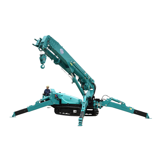
Maeda MC815C Manuals
Manuals and User Guides for Maeda MC815C. We have
3
Maeda MC815C manuals available for free PDF download: Operation Manual, Service Manual, Quick Operation Manual
Maeda MC815C Operation Manual (426 pages)
CRAWLER CRANE, Serial No. T0001 and up
Brand:
Maeda
| Category:
Construction Equipment
| Size: 10.98 MB
Table of Contents
Table of Contents
3
Item Page
4
Introduction
11
Introduction
12
For Safe Use of the Machine
13
Machine Overview
14
Specified Operations
14
Machine Structure
14
Machine Functions
15
Qualification for Operation
16
Qualification for Crane Operation
16
Terminology
17
Terms and Definitions
17
Diagram of Working Radius and Lifting Height
18
Rated Total Load Chart
19
How to Look at the Angle Indicator
25
Outline of Remote Controller
26
Feature
26
Configuration
26
Configuration of Remote Controller
26
Functions
27
Functions of Remote Controller
27
Dpf Overview
28
Dpf Function
28
Dpf Regeneration
28
Safety
31
Basic Precautions
32
Precautions on Handling Remote Control System
37
Precautions for Use of Engine and Electric Motor Specifications
41
Operation Related Precautions
42
Before Starting Engine
42
After Starting Engine
44
During Crane Work
49
Precautions for Terminating Crane Operation (Remote Control System)
60
Transport Precautions
61
Battery Handling Precautions
63
Maintenance Precautions
65
Precautions before Maintenance
65
Precautions During Maintenance
67
Safety Label Locations
72
Operation
83
Name of each Section
84
Machine Units
84
Description of Controls
85
Description of Monitor
86
Names and Description of Control Levers
108
Names and Description of Outrigger Operation Panel
113
Emergency Stop Switch
114
Starter Switch
114
Lock Lever
114
Accelerator Pedal
114
Light Switch
115
Disconnect Switch
115
Override Switch
116
Fuse Box
117
Cigar Socket
118
Maintenance Usb Port
118
Names and Description of Remote Control Parts
119
Transmitter and Receiver
119
Description of Remote Controller Accessories
123
Outrigger Safety Device
124
Functions of Outrigger Safety Devices
124
Moment Limiter (Overload Detector)
125
Configuration of Moment Limiter
125
Functions of Moment Limiter
126
Moment Limiter Operation
127
Moment Limiter Settings
129
Moment Limiter Functions
132
Moment Limiter Start Conditions
135
Override Switch
136
Troubleshooting for Moment Limiter
136
Over Hoist Detector
137
Operator Seat
138
Radiator Cover
140
Radiator Grille
141
Engine Cover
142
Machinery Cover
143
Operation Side Cover
144
Power Unit
145
Names of Power Unit Parts
145
Names of Power Supply Box Parts
145
Names of Inverter Parts
146
Operation
147
Pre-Operation Inspection
147
Visible Checks
147
Checking before Starting Engine
147
Inspection after Starting Engine
147
Starting Engine
148
Normal Starting of Engine
148
Starting Engine in Cold Environment
149
Operations and Checks after Starting Engine
150
Break-In Operation
152
Machine Travelling Posture
152
Start Moving Machine
153
Changing Machine Travelling Mode
154
Changing Direction of the Machine
154
Stopping/Parking the Machine
156
Stopping Engine
157
Inspection after Stopping Engine
157
Cautions in Driving
158
Outrigger/Crane Related Safety Devices
160
Outrigger Setting Operation
163
Outrigger Components
165
Outrigger Setup Operation
165
Cautions before Crane Operation
170
Operation before Crane Work
171
Crane Operation Posture
172
Winding and Unwinding
173
Boom Derricking Operation
173
Boom Telescoping Operation
174
Slewing Operation
175
Accelerator Operation
175
Crane Stowage Operation
176
Outrigger Stowage Operation
179
Prohibited Operations During Crane Work
183
Pick & Carry Operation
185
Cautions During Pick & Carry Operation
185
Pick & Carry Posture
186
Change to Pick & Carry Posture from Travelling Posture
186
Change to Pick & Carry Posture from Crane Mode Posture
187
Pick & Carry Operations
188
Canceling Pick & Carry Operation Posture
189
How to Return to Travelling Posture
189
How to Return to Crane Posture
190
Dpf Stationary Regeneration Method
191
Operation by Remote Ccontrol
192
Cautions before Operation
192
Powering on
193
Indications of Display
194
Starting/Stopping the Engine
198
Operation after Engine Is Started
198
Operation before Work
198
Switching Operation Mode
198
Travel Operation
199
Start Moving Machine
199
Changing Direction of the Machine
200
Stopping/Parking the Machine
201
Outrigger Operation
202
Outrigger Setting Operation
203
Outrigger Stowage Operation
206
Crane Operation
209
Hook Winding and Unwinding
210
Boom Derricking Operation
210
Boom Telescoping Operation
211
Slewing Operation
212
Operation While Traveling with a Suspended Load
213
Fly Jib Derricking/Telescoping Operation
213
Operating Speed Selector/Outrigger Select Switch
214
Operating Accelerator Control Switch
214
Operating Horm Switch
214
Emergencystop Switch Operation
215
Led Light Operations
215
Checking after Crane Operation
216
Crane Stowage Operation
216
Stopping Operation by Radio Control and Inspection
216
Operating Machine with Engine & Electric Motor
217
Power Supply Connection
217
Operation and Checking after Power Connection
220
Machine Operation
222
Machine Stop and Checks after Stopping Machine
222
Power Supply Separation
223
Handling Wire Rope
224
Criteria for Wire Rope Replacement
224
Corretive Actions against Twisted Wire Rope
225
Transportation
227
Loading/Unloading
227
Hoisting Machine
228
Cautions When Loading Machine
229
Cautions During Transportation
229
Handling Machine in Cold Environment
230
Preparing for Low Temperature
230
Long-Term Storage
232
Before Storing Machine
232
During Storage
232
After Storage
233
Handling Battery
234
Cautions in Handling Battery
234
Removing/Installing Battery
235
Cautions in Charging Battery
236
Starting Engine with Booster Cable
237
Handling Remote Controller Battery
239
Replacement Timing of Battery
239
Replacement Method of Battery
239
Charging Method of Battery
240
Troubleshooting
242
Electrical Components
242
Machine Body
243
Engine
244
Electric Motor
245
Before Remote Controller Failure Disgnosis
247
Remote Controller
248
List of Error Codes
249
Inspection and Maintenance
255
Precautions for Maintenance
256
Basic Maintenance
258
Legal Inspection
261
Periodic Replacement of Important Components
262
Consumables
263
Lubricating Oil
264
Use of Lubricating Oil According to Temperatures
264
Accessory Tools and Standard Tightening Torque
265
List of Standard Tightening Torque
265
List of Hose Tightening Torque
266
Inspection and Maintenance List
267
Maintenance Procedures
270
Pre-Operation Inspection
270
Inspection before Starting Engine (Patrol)
270
Inspection Around Crane
271
Inspection of Wire Rope
271
Inspection of Hook Block
271
Inspection Around Outrigger
271
Inspection Around Safe Rubber Track
272
Inspection Around Carrier
272
Inspection Around Engine
272
Inspection Around Carrier and Crane
272
Inspection before Starting Engine
273
Checking/Refilling Engine Coolant
273
Checking Oil Level and Refilling Oil in Engine Oil Pan
274
Checking Fuel Level and Refilling in Fuel Tank
275
Checking/Cleaning Fuel Pre-Filter
276
Checking Oil Level and Refilling Oil in Hydraulic Oil Tank
277
Checking Oil Level and Refilling Oil in Slewing Reduction Gear Case
278
Checking/Refilling Oil in Travelling Motor Reduction Gear Case
279
Inspecting/Cleaning of Radiator and Oil Cooler Fins
280
Inspecting/Refilling of Battery Electrolyte Level
281
Checking Horn for Operation
282
Checking Headlights for Operation
282
Inspection of Fuse
283
Inspection of Outrigger Display
283
Adjusting Operator Seat
284
Inspection before Starting Engine (Radio Control)
285
Checking Prior to Turning on the Transmitter
285
Checking after Turning on the Transmitter
286
[3 ] Checking of Receiver
287
Inspection after Starting Engine
288
Inspection of Outrigger Safety Equipment Operation
288
Checking Outrigger Operation
291
Checking Crane Operations
292
Inspection of over Hoist Detector
293
Inspection of Moment Limiter
293
Inspection of Outrigger Extension Position
294
Checking Engine Exhaust Gas Colour, Noise and Vibration
294
Inspection of Engine Start and Stop Operation (Radio Control)
295
Inspection of Engine Start Operation
295
Inspection of Engine Stop Operation
295
Inspection of Outrigger Mode Operation
296
Inspection of Crane Mode Operation
297
Irregular Maintenance
299
Inspection/Adjustment of Rubber Track Tension
299
Inspection/Adjustment of Rubber Track Shoe Bolt
300
Replacement of Winch Wire Rope
301
Inspection/Adjustment of Boom Telescoping Wire Rope
305
Replacement of Hydraulic Oil Suction Filter
308
Initial 10 Hour Maintenance
310
Initial 50 Hour Maintenance
310
Initial 250 Hours Maintenance
310
Greasing Machine Units
310
Oil Replacement in Hydraulic Oil Tank
310
Replacement of Hydraulic Oil Return Filter
310
Checking/Adjustment Alternator Belt Tension
310
Oil Replacement in Slewing Reduction Gear Case
310
Oil Replacement Oil in Winch Reduction Gear Case
310
Oil Replacement Oil in Travelling Motor Reduction Gear Case
310
Every 50 Hours Maintenance
311
Draining of Contaminant Water/Deposits in Fuel Tank
311
Draining of Contaminant Water/Deposits in Fuel Pre-Filter
312
Greasing of Machine Units
313
Every 100 Hours Maintenance
315
Inspecting/Refilling of Oil Level in Slewing Reduction Gear Case
315
Every 250 Hours Maintenance
316
Inspection/Cleaning of Air Cleaner
316
Inspection/Adjustment of Alternator Belt Tension
318
Checking/Refilling Oil in Travelling Motor Reduction Gear Case
319
Every 500 Hours Maintenance
320
Replacement Engine Oil and Engine Oil Filter Cartridge
320
Replacement of Air Cleaner
322
Replacement of Fuel Pre-Filter
323
Replacement of Fuel Filter Cartridge
324
Replacement Hydraulic Oil Return Filter Cartridge
325
Replacement of Hydraulic Oil Tank Air Filter
326
Inspection of Slewing Ring Mounting Bolt
327
Every 1000 Hours Maintenance
328
Cleaning of Engine Cooling System
328
Oil Replacement in Hydraulic Oil Tank
331
Oil Replacement in Slewing Reduction Gear Case
333
Oil Replacement in Winch Reduction Gear Case
334
Oil Replacement in Travelling Motor Reduction Gear Case
335
Inspection/Adjustment Engine Valve Clearance
335
Every 1500 Hours Maintenance
336
Every 2000 Hours Maintenance
336
Every 3000 Hours Maintenance
337
Specifications
339
Principal Specifications List
340
Specification Dimensional Drawing
343
Dimensional Drawing of Outrigger Width
344
Rated Total Load Chart
345
Fall Hook
345
Fall Hook
348
Fall Hook
351
Single Fall Hook
354
Working Radius/Lifting Height
357
Working Radius and Lifting Height (During Pick & Carry)
358
Item Page
359
Fly Jib
359
Cautions in Using Fly Jib
360
Mount Position of Fly Jib Safety Labels
361
Name of each Section of Fly Jib
365
Mounting and Storing Fly Jib
366
Mounting and Stowing Fly Jib
366
Mounting Fly Jib
367
Stowing Fly Jib
375
Handling Monitor and Moment Limiter
383
Name of Monitor Display
383
Monitor Display in Fly Jib Mode
383
Monitor Display in Fly Jib Stowage Mode
386
Moment Limiter Functions
387
Recovery Operation from Automatic Stop
387
Operation
388
Fly Jib Derricking Operation
388
Fly Jib Retract/Extend Operation
388
Troubleshooting
389
List of Error Code
389
When These Phenomena Happen
390
Inspection and Maintenance
391
Pre-Operation Inspection
391
Periodic Replacement of Critical Parts
393
Consumables
393
Maintenance Every 50 Hours
394
Specification
395
Specification Table
395
Specification Dimensional Drawing
395
Rated Total Load Chart
396
Working Radius/Lifting Height
397
Item Page
399
Searcher Hook
399
Cautions in Using Searcher Hook
400
Searcher Hook Safety Label Locations
401
Names of Searcher Hook Parts
404
Mounting and Stowing Searcher Hook
405
Mounting Searcher Hook
406
Stowing Searcher Hook
409
Removing Searcher Hook (Changing to Standard Specification)
411
Removing Searcher Hook Boom
411
Removing Bracket
412
Mounting Searcher Hook (Changing to Searcher Hook Specification)
413
Mounting Searcher Hook Boom
413
Attaching Bracket
414
Handling Monitor and Moment Limiter
415
Name of Monitor Display
415
Monitor Display in Searcher Hook Mode
415
Changing Searcher Hook Mode
417
Moment Limiter Functions
418
Recovery Operation from Automatic Stop
418
Operation
419
Changing Searcher Hook Angle
419
Troubleshooting
420
Inspection and Maintenance
421
Pre-Operation Inspection
421
Specification
422
Specification Table
422
Specification Dimensional Drawing
422
Rated Total Load Chart
423
Working Radius/Lifting Height
424
Advertisement
Maeda MC815C Service Manual (378 pages)
Crawler Crane
Brand:
Maeda
| Category:
Construction Equipment
| Size: 25.61 MB
Table of Contents
Table of Contents
3
Overview
11
External View
12
Standard Specifications
12
Searcher Hook Specifications
12
Fly-Jib Specifications
13
Dimensional Drawing of Outrigger Width
13
Principal Specifications List
14
Standard Specifications
14
Engine and Electric Motor Specifications
15
Remote Control Specifications
16
Component Mass List
17
Oil and Water Quantities List
18
Rated Total Load Chart
18
Falls
19
Falls
22
Falls
25
Single Fall
28
Working Radius/Lifting Height
31
Working Radius and Hoisting Height (Travelling with Hoisted Load)
32
Structure and Maintenance Procedure
33
Engine and Cooling-Related Components
34
Engine Specifications
34
Engine Mount
36
Pto (Power Take-Off)
37
Cooling System
38
Fuel Line
40
Fuel Tank
41
Power Transmission Schematic Diagram
42
Hydraulic System Diagram (Mc815C)
42
Swing Circle
43
Undercarriage and Frame
44
Track Frame
44
Idler Cushion
46
Idler
47
Track Roller
48
Carrier Roller
49
Sprocket
50
Track Shoe
51
Shoe Plate
51
Adjusting Rubber Track Tension
52
Hydraulic Units
54
Hydraulic Units Layout Diagram
54
Hydraulic Circuit Diagram
56
Hydraulic Oil Tank and Filter
58
Hydraulic Pump
59
Hydraulic Pump External View
59
Hydraulic Pump Connection Destinations
60
Hydraulic Pump Specifications
60
Pump Hydraulic Circuit Diagram
60
Shuttle Manifold Block
61
Travel / Outrigger Control Valve
62
Travel / Outrigger Control Valve External View
62
Travel / Outrigger Control Valve (Upper) Connection Destinations
63
Travel / Outrigger Control Valve (Lower) Connection Destinations
63
Hydraulic Specifications
64
Solenoid Valve Specifications
64
Travel / Outrigger Control Valve Layout
64
Travel / Outrigger Control Valve Circuit Diagram
65
Check Valve (Joint)
66
Crane Control Valve
67
Crane Control Valve External View
67
Crane Control Valve Connection Destinations
68
Crane Control Valve Circuit Diagram
68
Crane Control Valve Specifications
69
Crane Control Valve Layout
69
Slewing Motor
70
Slewing Motor External View
70
Slewing Motor Connection Destinations
70
Slewing Motor Specifications
70
Slewing Motor Internal Structure Diagram
71
Travelling Motor
72
Travelling Motor External View
72
Travelling Motor Connection Destinations
72
Travelling Motor Specifications
72
Travelling Speed Switching Valve Appearance / Specifications
73
Winch Motor Connection Destinations
74
Winch Motor
74
Winch Motor External View
74
Winch Motor Specifications
75
Winch Venting
76
Rotary Joint
77
Rotary Joint External View
77
Rotary Joint Specifications
78
Rotary Joint Connection Destinations
78
Rotary Joint Structure
78
Derrick Cylinder
79
Derrick Cylinder External View
79
Derrick Cylinder Specifications
80
Derrick Cylinder Connection Destinations
80
Counterbalance Valve (Identification Stamp "D" for Derricking Cylinder)
81
Counter-Balance Valve Operating Diagram
82
Telescopic Cylinder Assembly
83
Telescopic Cylinder External View
83
Telescopic Cylinder Connection Destinations
84
Telescopic Cylinder Specifications
84
Telescopic Cylinder Cross-Sectional Drawing
85
Telescopic Cylinder Hydraulic System Diagram
86
Sequence Valve
87
Mechanical Check Valve
88
Counter Balance Valve (Identification Stamp "T" for Telescoping Cylinder)
89
Outrigger Cylinder Assembly
90
Outrigger Cylinder External View
90
Outrigger Cylinder Connection Destinations
91
Outrigger Cylinder Specifications
91
Double Pilot Check Valve
92
Slide Cylinder Assembly
93
Slide Cylinder External View
93
Slide Cylinder Connection Destinations
94
Slide Cylinder Specifications
94
Or Select Valve
95
Oil Cooler
96
Return Manifold Block
97
P Lines (Pump - Shuttle Manifold Block Line)
98
Hydraulic Piping Diagram
98
P Lines (Pump Lines - Shuttle Manifold Block - Check Joint) Hydraulic System Diagram
100
P Lines (Shuttle Manifold Block - Travelling / Outrigger Control Valve Lines)
101
T.dr Lines
103
Travelling Lines
105
Outrigger Lines
107
Hydraulic Piping Crane Fixed Part Assembly
110
Hydraulic Piping Rotating Part Assembly (Derricking Lines)
112
Hydraulic Piping Rotating Part Assembly (Telescoping Lines)
113
Hydraulic Piping Rotating Part Assembly (Winch Lines)
114
Hydraulic Piping Rotating Part Assembly (Winch Drain Line)
115
Hydraulic Piping Rotating Part Assembly (Winch Brake Release / 2 Speed Switching Lines)
116
Boom Assembly
118
Work Equipment
118
Hook Block Assembly
120
Inspection of Hook Block
121
Electrical Equipment Connection Diagram (1/2 - 2/2)
126
Electrical Units
129
Cabin Interior
129
Name of each Control Part
129
Outrigger Operation Panel
130
Left Control Lever
131
Right Control Lever
133
Monitor
136
List of Error Codes
138
Consumables Display
143
Fuse Box
144
Controller
145
Controller Layout
145
Lower Part Controller Pin Numbers
147
Io Unit Pin Numbers
150
Harness Assembly
151
Harness Overview Figure
151
Harness Product Name / Number
151
Outrigger Sensor Harness
152
Engine Harness
153
Console Harness
154
Valve Harness
155
Display Harness
156
Boom Harness
157
Electrical Fittings Outside the Cabin
158
Led Light
158
Surveillance Cameras
159
Sensors
160
Pressure and Oil Temperature Sensors
160
Inclination Sensor
161
Fuel Sender Assembly
162
Rotary Brush
163
Safety Device
165
Configuration of Moment Limiter
165
Moment Limiter - Names for Monitor Indicators (Crane Mode)
166
Sensor Assembly
167
Length Meter (Standard Specification)
167
Length Meter (Boom Light Specification)
168
Angle Detector
169
Pressure Sensor
170
Over-Hoisting Prevention Device
171
Over Un-Winding Detection Device
172
Tri-Colour Revolving Working Status Lamp
173
Outrigger Safety Devices
174
Outrigger Position Detection Parts
174
Outrigger Grounding Detection Parts
175
Outrigger Rotary Position Detection Parts
176
Boom Stowing Position Detection Parts
177
Hook Grounding Detection Parts
178
Remote Control
179
Item Page
179
Components of the Transmitter
180
Names and Description of Remote Control Parts
180
Transmitter and Receiver
180
Description of Remote Controller Accessories
184
Handling Remote Controller Battery
185
Replacement Method of Battery
185
Replacement Timing of Battery
185
Charging Method of Battery
186
Before Remote Controller Failure Diagnosis
188
Troubleshooting
188
Remote Controller
189
Electrical Wiring Diagram for Remote Controller
190
Electrical Wiring Diagram for Remote Controller
191
Principal Specifications List
192
Service Locations
193
Electric Motor
195
Electric Power Unit
196
Electric Power Unit Part Names
196
Power Supply Box
196
Inverter Part Names
197
Electric Power Unit Assembly
198
Electric Motor
199
Electric Line Assembly
200
Electric Circuit Diagram for Electric Motor Specifications
202
Inverter Harness (Wire Harness of the Electrical Motor)
202
Troubleshooting
203
Principal Specification List (Machines with Engine & Electric Motor)
204
Fly Jib
205
Name of each Section of Fly Jib
206
Fly Jib Hydraulic System
207
Solenoid Operated Directional Control Valve (Jib Switching Sol)
207
Hose Reel
208
Derricking Cylinder (for Fly Jib)
209
Telescoping Cylinder (for Fly Jib)
210
Selector Valve Block (Fly Jib Telescopic Cylinder Mounted)
211
Fly Jib
212
Fly Jib (Main Boom Side)
212
Fly Jib (Fly Jib Side)
213
Fly Jib Harness 4.1 Fly Jib Harness
215
Fly Jib Safety Device
218
Pin Type Load Cell (Load Transducer)
218
Length Meter Reel (Fly Jib Mounted)
219
Angle Detector (Fly Jib Mounted)
220
Fly Jib Electrical Circuit Diagram
223
List of Error Codes
224
Troubleshooting
224
When These Phenomena Happen
225
Specification Dimensional Drawing
226
Specification Table
226
Specifications
226
Rated Total Load Chart
227
Working Radius/Lifting Height
228
Searcher Hook
229
Names of Searcher Hook Parts
230
Searcher Hook Assembly
231
Changing Searcher Hook Angle
232
Changing to Searcher Hook Mode
233
Troubleshooting
234
Specification Dimensional Drawing
235
Specification Table
235
Specifications
235
Rated Total Load Chart
236
Working Radius/Lifting Height
237
Disassembling and Assembling
239
Item Page
239
Dismounting and Mounting the Boom Assembly
240
Connection Diagram for Boom Equipment
241
Dismounting the Boom
241
Mounting the Boom
241
Disassembling and Assembling the Boom Assembly
242
Disassembling the No.1 Boom
242
Disassembling the No.2 Boom
243
Disassembling the No.3 Boom
244
Disassembling the No.4 Boom
245
Disassembling the Telescopic Cylinder from the No. 5 Boom
246
Dismounting and Mounting the Winch Wire Rope
247
Removal of Winch Wire Rope
247
Installation of Winch Wire Rope
248
Actions to Take When the Winch Wire Rope Is Twisted
250
Checking the Boom Telescoping Wire Rope
251
Checking/Adjusting Main Boom Telescoping Wire Rope
251
Adjusting the Boom Telescoping Wire Rope
252
Reference Values
255
Table of Engine Related Reference Values
256
Table of Machine Related Reference Values
257
Table of Moment Limiter Related Reference Values
260
Service Mode
261
Consumables
262
Crane Calibration
262
Error History
262
Function
262
Initial Setting
262
Ml Setting
262
Monitoring
262
Service Mode
262
Work History
262
Consumables
264
Work History
265
Error History
269
Initial Setting
269
Crane Calibration
271
Level Calibration
271
Potentiometer Calibration
272
Boom Angle Calibration
273
Boom Length Calibration
273
Load Calibration
274
Fly-Jib Angle Calibration
275
Fly-Jib Length Calibration
275
Fly-Jib Load Calibration
276
Ml Setting
277
Function
278
Table of Contents
284
Eo101H
302
Eo101L
302
Eo102H
303
Eo102L
303
Eo103L
304
Eo104L
305
Eo105L
306
Eo106L
307
Eo107L
308
Eo13H
309
Eo13L
309
Eoc01H
310
Eoc01L
310
Eoc02H
310
Eoc02L
310
Eoc03H
311
Eoc03L
311
Eoc04H
311
Eoc04L
311
Eoc05H
312
Eoc05L
312
Eoc06H
312
Eoc06L
312
Eoc07H
313
Eoc07L
313
Eoc08H
313
Eoc08L
313
Eoc10H
314
Eoc10L
314
Eof01H
316
Eof01L
316
Eof02H
316
Eof02L
316
Eoh01H
318
Eoh01L
318
Eoo01H
319
Eoo01L
319
Eoo02H
319
Eoo02L
319
Eoo03H
320
Eoo03L
320
Eoo04H
320
Eoo04L
320
Eoo05H
321
Eoo05L
321
Eoo06H
321
Eoo06L
321
Eoo07H
322
Eoo07L
322
Eoo08H
322
Eoo08L
322
Eop01H
323
Eop01L
323
Eos01H
324
Eos01L
324
Eos02H
324
Eos02L
324
Eos03H
325
Eos03L
325
Eos04H
325
Eos04L
325
Eot01H
326
Eot01L
326
Eot02H
326
Eot02L
326
Eot03H
327
Eot03L
327
Eot04H
327
Eot04L
327
Troubleshooting (Matters Other than Error Code Display)
347
Engine Start Fault
349
Engine Stall
350
Engine Hunting
351
Engine Output Shortage
352
Much Black Smoke in Exhaust Gas
353
Much White Smoke in Exhaust Gas
353
Abnormal Noise from Engine
354
Significant Fuel Consumption
354
Significant Oil Consumption
354
Monitor Displays Nothing
355
Troubleshooting of the Electrical Systems
355
Moment Limiter Indication Values on Monitor Are Questionable
356
Monitor Frozen and Inoperable
356
Monitor Switches Inoperable (Except for Being Frozen
356
Fuel Gauge Fails to Indicate Normally
357
Monitor Does Not Display Partially
357
Glow Lamp Does Not Function
359
Headlights Do Not Turn on Normally
359
Tri-Colour Revolving Working Status Lamp Does Not Come on
359
Travelling Speed Cannot be Changed
360
High Speed Operation of Winch Wind-Up/Down Cannot be Performed
361
Wind-Up Cannot be Performed with Hook Stowage Operation
361
None of All the Working Machines and the Slewing/Travelling Works
364
Abnormal Sound or Vibration Is Generated from Winch Motor or Its Periphery
367
Wind-Down Cannot be Performed
367
Wind-Up Cannot be Performed
367
Boom Telescoping Is Slow or Weak
368
Gear Positions 1 and 2 of Winch Cannot be Shifted
368
Boom Extending/Retracting Order Is Disturbed
369
Crane Cannot be Operated Discretely
369
Either Boom No. 2 or 3 Fails to Retract
369
Hunting Occurs During Boom Retraction
369
Time Lag of Crane Is Significant
370
Sway in Travelling Is Observed
371
Travelling Speed Is Slow
371
Steering Is Difficult or Weak
372
Travelling Rubber Track Fails to Move (One Side Only
372
Travelling Speed Cannot be Changed, or Travelling Speed Is Slow/High
372
Does Not Slew
373
Slewing Acceleration Is Unsatisfactory, or Slewing Speed Is Slow
374
Overrun after Stop of Slewing Is Significant
375
Abnormal Sound Generated at a Stop of Slewing Is Loud
376
Impact at a Stop of Slewing Is Significant
376
Natural Descending Amount at Slewing Is Significant
376
Maeda MC815C Quick Operation Manual (24 pages)
Crawler Crane
Brand:
Maeda
| Category:
Construction Equipment
| Size: 0.98 MB
Table of Contents
Table of Contents
3
1 Description of Controls
4
Outrigger Operation Panel
4
Control Levers
5
2 Description of Monitor
6
3 Operations
10
Starting / Stopping Engine
10
Travelling Operation
11
Outrigger Operation
12
Crane Operation
16
Crane Stowage Operation
17
4 Remote Control
19
Starting / Stopping Engine
19
Travelling Operation
20
Outrigger Operation
21
Crane Operation
22
Advertisement
Advertisement
Related Products
Maeda HIRD MC815
Maeda MC-174CRM
Maeda MC-305C-2
Maeda MC-405C
Maeda MC-285C
Maeda MC285C-3
Maeda MC405C-3
Maeda MC285CB-3
Maeda MC305C-3
Maeda MC174
Maeda Categories
Construction Equipment
More Maeda Manuals
Login
Sign In
OR
Sign in with Facebook
Sign in with Google
Upload manual
Upload from disk
Upload from URL