Table of Contents
Advertisement
Quick Links
This manual covers equipment which is no
longer in production by The Lincoln Electric Co.
Speci cations and availability of optional
features may have changed.
Safety Depends on You
Lincoln arc welding and cutting
equipment is designed and built
with safety in mind. However, your
overall safety can be increased by
proper installation ... and thought-
ful operation on your part. DO
NOT INSTALL, OPERATE OR
REPAIR THIS EQUIPMENT
WITHOUT
READING
MANUAL AND THE SAFETY
PRECAUTIONS CONTAINED
THROUGHOUT.
nd, most
importantly, think before you act
and be careful.
ISO 9001
ANSI RAB
QMS
Designed and Manufactured Under a
Quality Program Certified by
ABS Quality Evaluations, Inc.
to ISO 9001 Requirements.
CERTIFICATE NUMBER: 30273
• Sales and Service through Subsidiaries and Distributors Worldwide •
Cleveland, Ohio 44117-1199 U.S.A. TEL: 216.481.8100 FAX: 216.486.1751 WEB SITE: www.lincolnelectric.com
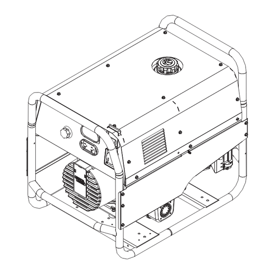
BULLDOG ™140
For Machines with Code Number 11518
THIS
Various engine configurations are available and machine appearance will vary
accordingly.
OPERATOR'S MANUAL
• World's Leader in Welding and Cutting Products •
IM10005
Copyright © Lincoln Global Inc.
June, 2009
Advertisement
Table of Contents

Related Manuals for Lincoln Electric BULLDOG 140


Summary of Contents for Lincoln Electric BULLDOG 140
- Page 1 BULLDOG ™140 June, 2009 For Machines with Code Number 11518 This manual covers equipment which is no longer in production by The Lincoln Electric Co. Speci cations and availability of optional features may have changed. Safety Depends on You Lincoln arc welding and cutting equipment is designed and built with safety in mind.
- Page 2 THANK YOU FOR SELECTING A QUALITY PRODUCT BY KEEP YOUR HEAD OUT OF THE FUMES. DON’T get too close to the arc. LINCOLN ELEC TRIC. Use corrective lenses if necessary to stay a reasonable distance away from the arc. READ and obey the Safety Data PLEASE EXAMINE CARTON AND EQUIPMENT FOR Sheet (SDS) and the warning label DAMAGE IMMEDIATELY...
- Page 3 W117.2-1974. A Free copy of “Arc Welding Safety” booklet E205 is available from the Lincoln Electric Company, 2.d. All welders should use the following procedures in order to 22801 St. Clair Avenue, Cleveland, Ohio 44117-1199.
- Page 4 SAFETY ELECTRIC SHOCK ARC RAYS CAN BURN. CAN KILL. 3.a. The electrode and work (or ground) circuits are 4.a. Use a shield with the proper filter and cover plates to protect your electrically “hot” when the welder is on. Do eyes from sparks and the rays of the arc when welding or not touch these “hot”...
- Page 5 SAFETY WELDING AND CUTTING CYLINDER MAY EXPLODE IF SPARKS CAN CAUSE DAMAGED. FIRE OR EXPLOSION. 7.a. Use only compressed gas cylinders containing the correct shielding gas for the process used 6.a. Remove fire hazards from the welding area. If and properly operating regulators designed for this is not possible, cover them to prevent the welding sparks the gas and pressure used.
- Page 6 SAFETY 5. Toujours porter des lunettes de sécurité dans la zone de PRÉCAUTIONS DE SÛRETÉ soudage. Utiliser des lunettes avec écrans lateraux dans les zones où l’on pique le laitier. Pour votre propre protection lire et observer toutes les instruc- tions et les précautions de sûreté...
-
Page 7: Table Of Contents
TABLE OF CONTENTS Page Safety i-iv Installation ..........................Section A Technical Specifications ......................A-1 Safety Precautions........................A-2 Location and Ventilation ......................A-2 Stacking, tilting and Lifting ......................A-3 Pre-operation Engine Service .....................A-3 Oil, Fuel and Spark Arrester......................A-3 Electrical Output Connections and Welding Cable Size, Lengths..........A-4 Machine Grounding and Auxiliary Power Receptacles...............A-5 Premises Wiring and Circuit Breakers ..................A-6 Electrical Devises used with the BULLDOG™... -
Page 8: Installation
INSTALLATION TECHNICAL SPECIFICATIONS - BULLDOG™ 140 K2708-1 INPUT - GASOLINE ENGINE Manufacturer Description Speed Displacement Ignition Capacities Robin / Subaru 1 cyl., 3700 RPM 17.51 cu. in. Manual, Fuel: 6.86 gal. (24.9 l) EX 30 4 cycle ± 50 RPM (287 cc) Recoil start;... -
Page 9: Safety Precautions
INSTALLATION SAFETY PRECAUTIONS LOCATION AND VENTILATION Read this entire installation section before you Whenever you use the BULLDOG™ 140, be sure that start installation. clean cooling air can flow through the machine’s gasoline engine and the generator. Avoid dusty, dirty areas. -
Page 10: Pre-Operation Engine Service
INSTALLATION STACKING The BULLDOG™ 140 is shipped with the engine BULLDOG™ 140 machines CANNOT be stacked. filled with SAE 10W30 oil. CHECK THE OIL LEVEL BEFORE YOU START THE ENGINE. This is an TILTING added precaution. Do not screw in dipstick when checking oil level. - Page 11 INSTALLATION BULLDOG™ 140 OUTPUT CONNECTIONS FIGURE A.1 1. CURRENT CONTROL DIAL 5. RECEPTACLE - 240 VOLT, 50 AMP 2. WELD OUTPUT TERMINALS (2) 6. DUPLEX RECEPTACLE (2)- 120 VOLT, 20 3. GROUND STUD 4. CIRCUIT BREAKER 20 Amp 7. HOUR METER TABLE A.1 ELECTRICAL OUTPUT RECOMMENDED WELDING CABLE...
- Page 12 ----------------------------------------------------------- ----------------------------------------------------------- Lincoln Electric offers a welding accessory kit with AUXILIARY POWER RECEPTACLES the properly specified welding cables. See the ACCESSORIES section of this manual for more infor- The control panel of the BULLDOG™ 140 features mation.
- Page 13 INSTALLATION PREMISES WIRING The BULLDOG™ 140 is not recommended for premises wiring. The BULLDOG™ 140 does not have a combined 120/240 volt receptacle and cannot be connected to a premises as described in other Lincoln literature. Remember that the BULLDOG™ 140 is intended only for backup, intermittent use power.
-
Page 14: Electrical Devises Used With The Bulldog™ 140
DO NOT USE THESE DEVICES WITH A BULLDOG™ 140. The Lincoln Electric Company is not responsible for any damage to electrical components improperly connect- ed to the BULLDOG™ 140. BULLDOG™ 140... -
Page 15: Operation
OPERATION SAFETY INSTRUCTIONS GENERAL DESCRIPTION The BULLDOG™ 140 is a generator/welder designed for Read and understand this entire section before oper- home use and other non-commercial applications. As a ating your BULLDOG™ 140. generator it can supply up to 4,000 continuous watts (or WARNING 5,500 surge watts) of 120/240 volt, single-phase AC power. -
Page 16: Limitations
OPERATION LIMITATIONS • The BULLDOG™ 140 is not recommended for any 4. WELD WORK OUTPUT TERMIN L: Provides the processes besides those that are normally per- connection point for the work cable. formed using stick welding (SMAW) procedures. 5. GROUND STUD: Provides a connection point for •... - Page 17 OPERATION GASOLINE ENGINE CONTROLS 6. CHOKE: Provides a richer air/fuel mix- ture for cold engine starting condi- Refer to your engine manual for the location of the tions. See the topic ENGINE OPERA- following features: TION, below, for details on setting the choke.
- Page 18 OPERATION 4. Pull the cord rapidly. BEFORE STARTING THE ENGINE 5. If the engine does not start, open the choke CHECK AND FILL THE ENGINE OIL LEVEL: slightly and pull the starter cord rapidly again. 1. Place the machine on a level When the engine starts, gradually open the choke surface.
- Page 19 OPERATION GENERATOR OPERATION STOPPING THE ENGINE 1. Remove all welding and generator power loads CAUTION and let the engine cool by running it for several minutes. 2. Stop the engine by placing the “ON/OFF” switch Be sure that any electrical equipment plugged into in the “OFF”(O) position.
- Page 20 OPERATION TABLE B.1 GENERATOR POWER APPLICATIONS Suggested Power Applications Running Watts *Start-up Watts (Continuous) (Surge) *Air Compressor - 1 HP 2,000 4,000 - 8,000 *Air Compressor - 3/4 HP 1,250 3,100 - 5,000 *Airless Sprayer - 1/3 HP 1,500 - 2,400 Chain Saw 1,200 Circular Saw...
- Page 21 OPERATION WELDING OPERATION 7. Strike an arc and begin welding. For information on welding techniques, see WELDING GUIDE- GENERAL INFORMATION LINES in this section of the manual. WARNING AFTER YOU FINISH THE WELD: 1. Stop the gasoline engine. See ENGINE OPERA- ELECTRIC SHOCK can kill.
- Page 22 Feeder/Welder is equipped with all the supplies need- sole responsibility of the builder/user. Many vari- ed for Flux-Cored Arc Welding (FCAW). Also some ables beyond the control of The Lincoln Electric Wire Feeder/Welders come equipped with the essen- Company affect the results obtained in applying tials needed for Gas Metal Arc Welding, GMAW, or this type of information.
- Page 23 OPERATION No one can learn to weld simply by reading about it. The electric arc is made between the work and the tip Skill comes only with practice. The following pages end of a small metal wire, the electrode, which is will help the inexperienced welder understand welding clamped in a holder that is held by the welder.
- Page 24 B-10 B-10 OPERATION The function of the covered electrode is much more 2. The Correct Way to Strike An Arc than simply to carry current to the arc. The electrode is composed of a core metal wire around which has Be sure the work clamp makes good electrical contact been extruded and baked a chemical covering.
- Page 25 B-11 B-11 OPERATION These higher carbon steels can be welded successful- PRACTICE ly in most cases; however, care must be taken to fol- The best way of getting practice in the four skills that low proper procedures, including preheating the metal enable you to maintain: to be welded and, in some cases, carefully controlling the temperature during and after the welding process.
- Page 26 B-12 B-12 OPERATION Now weld the two plates together. Weld from left to Fillet Joints right (if right-handed). Point the electrode down in he gap between the two plates, keeping the electrodes slightly tilted in the direction of travel. When welding fillet joints, it is very important to hold the electrode at a 45°...
- Page 27 B-13 B-13 OPERATION 8. When the arc is brought back to the now solidified Vertical-Up Welding puddle, IT MUST BE SHORT, otherwise no metal will be deposited, the puddle will melt again, and it The problem, when welding vertical-up, is to put the will “drip”.
- Page 28 B-14 B-14 OPERATION 4. Move rapidly enough to stay ahead of the molten Overhead Welding slag. A whipping technique may be used to further minimize burn through. Various techniques are used for overhead welding. 5. If you have a choice, use lap joints rather than fil- However, in the interest of simplicity for the inexperi- lets or butts;...
- Page 29 B-15 B-15 OPERATION 4. The bead should be put on with a weaving motion, and it should be 1/2-3/4” (12.7-19.0mm) wide. Do When breaking not let the arc blow over the edge, as that will dull the weld stays on the edge.
- Page 30 B-16 B-16 OPERATION In some instances a back-up strip may be used and High-Speed Group (AWS E6013) plates may be gapped 1/8” (3.2mm) or more, as This group includes electrodes which have a moder- shown in figure (b). ately forceful arc and deposit rates between those of the out-of-position and high-deposit electrodes.
-
Page 31: Accessories
ACCESSORIES OPTIONS/ACCESSORIES LINCOLN ELECTRIC ACCESSORIES The following options/accessories are available for your BULLDOG™ 140 from your local Lincoln Distributor. Accessory Kit (K875) – Includes the following: • 20 Ft.(6.1m) #6 welding cable with lug. • 15 Ft.(4.6) #6 work cable with lugs. -
Page 32: Maintenance
MAINTENANCE SAFETY PRECAUTIONS OIL: Check the oil level after every 5 hours of operation or daily. BE SURE WARNING TO MAINTAIN THE OIL LEVEL. Change the oil the first time after 20 hours of opera- tion. Then, under normal operating conditions, •... - Page 33 MAINTENANCE FUEL: At the end of each day’s use, refill Clean Finger Guard Area: If your BULLDOG™ 140 is the fuel tank to minimize moisture conden- equipped with an engine that has a finger guard, you sation and dirt contamination in the fuel line. should clean it as often as needed, to remove dirt or debris that may collect on the fin areas.
- Page 34 MAINTENANCE SPARK PLUG SERVICE Replace or clean engine maintenance parts per the interval outlined in the engine owner’s manual. To service spark plug, remove the 8 screws securing the side panel. See Figure D.4. OPERATIONAL CLEARANCE FIGURE D.4 Approximately 12-18” of clearance should be around this unit during operation for air flow.
- Page 35 MAINTENANCE GENERATOR/WELDER MAINTENANCE RECEPTACLES: Keep the electrical receptacles in good condition. Remove any dirt, oil, or other STORAGE: Store the BULLDOG™ 140 in clean, debris from their surfaces and holes. dry, protected areas. CABLE CONNECTIONS: Check the welding cable CLEANING: Blow out the generator and controls connections at the weld output terminals often.
- Page 36 MAINTENANCE FIGURE D.7. - MAJOR COMPONENT LOCATIONS 1. CRADLE ASSEMBLY 2. ROTOR, BLOWER, AND BEARING ASSEMBLY 3. STATOR ASSEMBLY 4. BRUSH, BRUSH HOLDER ASSEMBLY AND BEARING BRACKET END COVER 5. REAR CONTROL PANEL 6. REAR PANEL ASSEMBLY 7. FUEL TANK ASSEMBLY 8.
- Page 37 HOW TO USE TROUBLESHOOTING GUIDE WARNING Service and Repair should only be performed by Lincoln Electric Factory Trained Personnel. Unauthorized repairs performed on this equipment may result in danger to the technician and machine operator and will invalidate your factory warranty. For your safety and to avoid Electrical Shock, please observe all safety notes and precautions detailed throughout this manual.
- Page 38 TROUBLESHOOTING Observe all Safety Guidelines detailed throughout this manual PROBLEMS POSSIBLE RECOMMENDED (SYMPTOMS) CAUSE COURSE OF ACTION PROBLEMS No generator power or welding output. 1. Disconnect anything plugged into auxiliary receptacles and weld loads. 2. Open lead in flashing or field circuit. 3.
- Page 39 TROUBLESHOOTING Observe all Safety Guidelines detailed throughout this manual PROBLEMS POSSIBLE RECOMMENDED (SYMPTOMS) CAUSE COURSE OF ACTION PROBLEMS Unit will weld but low or no generator 1. Circuit breaker open. power is available. 2. Loose or open connection with elec- trical plug-in component.
- Page 40 TROUBLESHOOTING Observe all Safety Guidelines detailed throughout this manual PROBLEMS POSSIBLE RECOMMENDED (SYMPTOMS) CAUSE COURSE OF ACTION PROBLEMS Engine will not start. 1. Spark plug boot or wire off, loose or wet. 2. Fuel shutoff valve is closed. 3. Low oil and engine low oil shutdown protection will not allow unit to start.
- Page 41 DIAGRAMS Enhanced Diagram BULLDOG™ 140...
- Page 42 DIMENSION PRINT BULLDOG™ 140...
- Page 43 NOTES BULLDOG™ 140...
- Page 44 Do not touch electrically live parts or Keep flammable materials away. Wear eye, ear and body protection. WARNING electrode with skin or wet clothing. Insulate yourself from work and ground. Spanish No toque las partes o los electrodos Mantenga el material combustible Protéjase los ojos, los oídos y el AVISO DE bajo carga con la piel o ropa moja-...
- Page 45 Keep your head out of fumes. Turn power off before servicing. Do not operate with panel open or WARNING Use ventilation or exhaust to guards off. remove fumes from breathing zone. Spanish Los humos fuera de la zona de res- Desconectar el cable de ali- No operar con panel abierto o AVISO DE...
- Page 46 • World's Leader in Welding and Cutting Products • • Sales and Service through Subsidiaries and Distributors Worldwide • Cleveland, Ohio 44117-1199 U.S.A. TEL: 216.481.8100 FAX: 216.486.1751 WEB SITE: www.lincolnelectric.com...
Need help?
Do you have a question about the BULLDOG 140 and is the answer not in the manual?
Questions and answers