Table of Contents
Advertisement
Quick Links
IM422-A
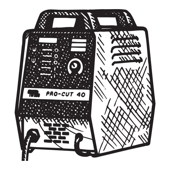
PRO - CUT
40
™
October, 1995
PLASMA CUTTING POWER SOURCE - for Single Phase Input - Code Numbers 9628-1 & 9628-2 only
Safety Depends on You
Lincoln plasma cutting equipment
is designed and built with safety in
mind. However, your overall safety
can be increased by proper instal-
lation ... and thoughtful operation
on your part. DO NOT INSTALL
OPERATE OR REPAIR THIS
EQUIPMENT WITHOUT READ-
ING THIS MANUAL AND THE
SAFETY PRECAUTIONS CON-
TAINED THROUGHOUT. And,
most importantly, think before you
act and be careful.
OPERATOR'S MANUAL
World's Leader in Welding and Cutting Products
Premier Manufacturer of Industrial Motors
Sales and Service through Subsidiaries and Distributors Worldwide
22801 St. Clair Ave. Cleveland, Ohio 44117-1199 U.S.A. Tel. (216) 481-8100
Advertisement
Table of Contents
Troubleshooting

Related Manuals for Lincoln Electric PRO-CUT 40


Summary of Contents for Lincoln Electric PRO-CUT 40
- Page 1 IM422-A PRO - CUT ™ October, 1995 PLASMA CUTTING POWER SOURCE - for Single Phase Input - Code Numbers 9628-1 & 9628-2 only Safety Depends on You Lincoln plasma cutting equipment is designed and built with safety in mind. However, your overall safety can be increased by proper instal- lation ...
-
Page 2: Safety Precautions
WARNING PLASMA CUTTING or GOUGING can be hazardous. PROTECT YOURSELF AND OTHERS FROM POSSIBLE SERIOUS INJURY OR DEATH. KEEP CHILDREN AWAY. PACEMAKER WEARERS SHOULD CONSULT WITH THEIR DOCTOR BEFORE OPERATING. Read and understand the following safety highlights. For additional safety information it is strongly recommended that you pur- chase a copy of “Safety in Welding &... - Page 3 4.g. Sparks and spatter are thrown from the plasma arc. Wear PLASMA ARC can injure. safety glasses, ear protection and oil free protective garments such as leather gloves, heavy shirt, cuffless trousers, high shoes and a cap over your hair. Wear ear plugs when cutting or gouging out of position or in confined places.
- Page 4 zones où l’on pique le laitier. PRÉCAUTIONS DE SÛRETÉ 6. Eloigner les matériaux inflammables ou les recouvrir afin de Pour votre propre protection lire et observer toutes les instructions prévenir tout risque d’incendie dû aux étincelles. et les précautions de sûreté specifiques qui parraissent dans ce manuel aussi bien que les précautions de sûreté...
-
Page 5: Table Of Contents
Replacement of Power Modules and Out put Diodes...........23 Environmental Protection .....................24 PRO-CUT 40 Status Lights Operating Modes ..............24 Procedure for Replacing P.C. Boards.................25 Wiring Diagram PRO-CUT 40.....................26 Parts Lists........................Appendix PRO-CUT 40 Torch and Cable Figure 1 ...............Appendix – 5 –... -
Page 6: Introductory Information
Thank You for selecting a QUALITY product by Lincoln Electric. We want you to take pride in operating this Lincoln Electric Company product ••• as much pride as we have in bringing this product to you! Please Examine Carton and Equipment For Damage Immediately When this equipment is shipped, title passes to the purchaser upon receipt by the carrier. -
Page 7: Product Description
1/2 high voltages involved with the plasma process. inch is 70 (°F). The PRO-CUT 40 comes with an air regulator, coarse USER RESPONSIBILITY air filter, oil coalescing filter, and pressure gauge. The system is available with a 25 ft. -
Page 8: Installation
A source of clean, dry, compressed air or nitrogen around the periphery of the building are recommended. must be supplied to the PRO-CUT 40. Oil in the air is a severe problem and must be avoided. The supply pressure must be between 70 and 150 psi (482 and 1032 kPa). -
Page 9: Electrical Input Connection
“230” to “208” of terminal strip “1”. See following instruc- tions. NOTE: Do not power the PRO-CUT 40 off of the auxiliary power supply of an engine driven welder. If the voltage peaks from the engine welder exceed 380V the filter capaci- BLACK tors, FETS of other circuity may fail on the PRO-CUT 40. -
Page 10: Air Input Connections
Torch Connection -The “Output On” LED will light. The PRO-CUT 40 comes factory equipped with a cut- -The pilot arc will run for 3.0 seconds and shut ting torch. Cutting torches come with a 25 ft. (7.6 m) off unless the plasma is brought in contact with or a 50 ft. -
Page 11: Pilot Arc Discussion
Pilot Arc Discussion: The PRO-CUT 40 has a smooth, continuous pilot arc. The pilot arc is only a means of transferring the arc to the workpiece for cutting. Repeated pilot arc starts, in Expanded Metal: rapid succession, is not recommended. -
Page 12: Thick Sections Of Metal
• Use the proper machine setting. Cranking the • The PRO-CUT 40 is capable of operation with a machine to maximum output will not produce 50 ft. (15.2 m) plasma torch. Pilot arc operation the best cutting performance in most situations. -
Page 13: Maintenance Procedures
MAINTENANCE PROCEDURES Check the filter elements every several months to see if they are clogged (weekly in very dirty environments). Replace if necessary. WARNING ELECTRIC SHOCK CAN KILL. Inspect the cable periodically for any slits or puncture marks in the cable jacket. Replace if BEFORE PERFORMING ANY MAINTE- necessary. -
Page 14: Troubleshooting Procedures
TROUBLESHOOTING PROCEDURES TROUBLESHOOTING GUIDE WARNING WARNING ELECTRICAL SHOCK CAN KILL. ELECTRIC SHOCK CAN KILL. Turn off machine at the disconnect switch at the back BEFORE PERFORMING ANY MAINTE- of the machine before tightening, cleaning or replacing NANCE THAT REQUIRES OPENING consumables. -
Page 15: Troubleshooting Steps
SYMPTOM CHECK No LED’s light and the fan does not operate when Check the input power to be sure it is on. the power switch is turned on. Check the power line fuses and machine connection. Replace line switch. No LED’s light when the power switch is turned Disconnect plug P5 from jack J5 at the on, but the fan operates. - Page 16 SYMPTOM CHECK b. If there is 115VAC between J18-1 and J18-4, check for less than 0.5 VDC between J5-5 (+, lead number 255A or 255B) and J5-2 (-, lead number 272). If voltage is OK, replace the air solenoid. If voltage is high, (approx. 5.5 VDC), replace the pressure switch.
- Page 17 SYMPTOM CHECK The air begins to flow, the “OUTPUT ON” LED Check the torch consumables to be sure they lights for a brief period and then the are in tight, not dirty or greasy, and in good “MALFUNCTION” LED begins blinking. No arc is shape.
- Page 18 SYMPTOM CHECK The “MALFUNCTION” LED is lit. The MALFUNCTION circuit monitors the torch to see if it is shorted as well as internal machine failures. Check the torch consumables to see if they are melted together or are simply touching each other.
-
Page 19: Troubleshooting Tests
TEST STEPS Step Test Check * Test Result Conclusion Next Repair Action Test Step FET A1 in circuit Terminals on test Switch PC Board: 1/8 (pos) >1K ohms FET OK to 12 (neg) <100 ohms Short Replace Switch PC Remove leads Board 4/5 and 1/8 from Switch PC Board... - Page 20 Step Test Check * Test Result Conclusion Next Repair Action Test Step Snubber resis- Disconnect leads tors 401 thru 404 on Switch PC Boards. Measure 25 ohms R4 OK across leads: high resistance R4 open Replace R4 401 to 12 25 ohms R5 OK 402 to 9...
- Page 21 Step Test Check * Test Result Conclusion Next Repair Action Test Step D9 Input 13 (pos) to T1 Rectifier (neg) >1K ohms <100 ohms Shorted Replace D9 In space S1 Test C1 and C2 13 (pos) to T2 (neg) >1K ohms Replace D9 <100 ohms Shorted...
- Page 22 Step Test Check * Test Result Conclusion Next Repair Action Test Step 5 (con’t) 12 (neg) to T3 (pos) >1K ohms (3 phase only) <100 ohms Shorted Replace D9 Inspect S1 Test C1 and 13 (neg) to T1 (pos) <100 ohms >1K ohms Open Replace D9...
-
Page 23: Switch Pc Board Repairs
SWITCH PC BOARD REPAIRS 9) Carefully holding the Switch PC board, install the 4 socket headcap screws but do not tighten them. Next, install the 2 hex headcap screws If a test indicates that one or more FET’s are defec- into the capacitor but do not tighten them. -
Page 24: Environmental Protection
N.A. Corning 3140, 3145, 738, Columbus Adhesives 0172 (M16100-1, -2) or GE RTV-162 is recommended. Sealant may also be purchased from Lincoln Electric (order E2519 Input Diode 6 Inch-Lbs. ** 26 Inch-Lbs. Silicone Rubber RTV coating). Apply sealant after the (M15454-1) machine is repaired and tested. -
Page 25: Procedure For Replacing Pc Boards
STATUS LIGHTS CONDITION SUGGESTIONS Safety It is possible that this light could turn on when power is first If machine can be reset, it is OK to continue operation. applied to machine. The nozzle is not in place. Securely fasten nozzle in place. While cutting if the voltage between the nozzle and By pressing reset, the machine will be functional. -
Page 26: Wiring Diagram Pro-Cut 40
WIRING DIAGRAM - PROCUT 40 – 26 –... - Page 27 Month Year USE THIS FORM TO ORDER: Order from: BOOK DIVISION, The Lincoln Electric Company, 22801 St. Clair Avenue, Cleveland, Ohio 44117-1199 for fastest service, FAX this completed form to: 216-361-5901 BOOKS OR FREE INFORMATIVE CATALOGS Telephone: 216-383-2211 or, Lincoln Welding School...
- Page 28 ● ● ● Do not touch electrically live parts or Keep flammable materials away. Wear eye, ear and body protection. WARNING electrode with skin or wet clothing. ● Insulate yourself from work and ground. Spanish ● ● ● No toque las partes o los electrodos Mantenga el material combustible Protéjase los ojos, los oídos y el AVISO DE...
- Page 29 ● ● ● Keep your head out of fumes. Turn power off before servicing. Do not operate with panel open or ● WARNING Use ventilation or exhaust to guards off. remove fumes from breathing zone. Spanish ● Los humos fuera de la zona de res- ●...
- Page 30 STATEMENT OF WARRANTY: TO OBTAIN WARRANTY COVERAGE: The Lincoln Electric Company (Lincoln) warrants to the You are required to notify Lincoln Electric, your Lincoln original purchaser (end-user) of new equipment that it will Distributor, Lincoln Service Center or Field Service Shop of be free of defects in workmanship and material.
Need help?
Do you have a question about the PRO-CUT 40 and is the answer not in the manual?
Questions and answers
Принципиальная схема плазмо резки