Sign In
Upload
Download
Table of Contents
Contents
Add to my manuals
Delete from my manuals
Share
URL of this page:
HTML Link:
Bookmark this page
Add
Manual will be automatically added to "My Manuals"
Print this page
×
Bookmark added
×
Added to my manuals
Manuals
Brands
Becker Manuals
Water Pump
T 4.10
Operating instructions manual
Becker T 4.10 Operating Instructions Manual
Hide thumbs
1
Table Of Contents
2
3
4
5
6
7
8
9
10
11
12
13
14
15
16
17
18
19
20
21
22
23
24
25
26
27
28
29
30
31
page
of
31
Go
/
31
Contents
Table of Contents
Troubleshooting
Bookmarks
Table of Contents
Table of Contents
To the Operating Instructions General
Structure of the Safety Instructions
Safety Symbols
Additional Documentation
Modifications and Conversions
Basic Safety Instructions
Provision
Obligations of the Operator
Obligations of the Staff
Staff Qualification
Intended Use
Inadmissible Use
Protective Measures for Users
Information on Residual Risks
Safety Instructions
2.10 Behaviour in Case of Danger and Accidents
Requirement for Stability
Occupational Safety and Health
Airborne Sound Emissions
2.14 Ergonomics
Ökodesign-Verordnung (Eu) 2019/1781
Operating Conditions
Pump Description
General Description of the Pump
Sizes
Variants
Component Illustration
Motors
Safety and Protective Devices
Testing the Safety and Protective Devices
Transport
Installation and Commissioning
General Requirements
Preparatory Activities
Connecting the Media Line
Adjust Valve
Electrical Installation
Electrical Connection
Switch on Pump
Normal Operation
Switch off Pump
Recommissioning
Troubleshooting / Troubleshooting
Fault Tables
Maintenance, Servicing and Dismantling
Maintenance and Servicing
Preparation
Maintenance Intervals
Maintenance Activities
Clean Filter
Check Rotary Vane
Media Lines
Conditions for Reconnection
Spare and Wear Parts
Temporary Decommissioning
Cleaning
8.10 Dismantling and Decommissioning
Storage
8.12 Disposal
Product Data Sheet
Product Overview
Operating Parameters
Technical Data
Advertisement
Quick Links
Download this manual
1 |
T 4.10, T 4.16, T 4.25, T 4.40, X 4.10, X 4.16, X 4.25, X 4.40
TRANSLATION OF THE OPERATING INSTRUCTIONS
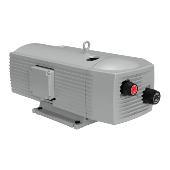
T 4.10/16/25/40
X 4.10/16/25/40
ROTARY VANE-
PRESSURE-VACUUM PUMP
dry-running
MAKE IT
BECKER.
Table of
Contents
Previous
Page
Next
Page
1
2
3
4
5
Advertisement
Table of Contents
Need help?
Do you have a question about the T 4.10 and is the answer not in the manual?
Ask a question
Questions and answers
Related Manuals for Becker T 4.10
Water Pump Becker T 4.25 DSK Operating Instructions
(4 pages)
Water Pump Becker T 4.25 DSK Operating Instructions
(4 pages)
Water Pump Becker T 4.25 DV Operating Instructions
(4 pages)
Water Pump Becker T 4.16 DV Operating Instructions
(4 pages)
Water Pump Becker T 4.16 DV Operating Instructions
(4 pages)
Water Pump Becker TLF 2.250 Maintenance Manual
(18 pages)
Water Pump Becker T 4.25 Operating Instructions Manual
(31 pages)
Water Pump Becker T 4.40 Operating Instructions Manual
(31 pages)
Water Pump Becker T Series Operating Instructions Manual
(6 pages)
Water Pump Becker VTLF 2.250 Operating Instructions Manual
(6 pages)
Water Pump Becker BCV 300 Operating Instructions Manual
Oil-free claw vacuum pump (6 pages)
Water Pump Becker VT 4.40 Operating Instructions
(4 pages)
Water Pump Becker VT 4.25 Operating Instructions Manual
(6 pages)
Water Pump Becker VTLF 2.200 Operating Instructions Manual
(8 pages)
Water Pump Becker DVT 3.80 Operating Instructions Manual
(8 pages)
Water Pump Becker U 4.100 Operating Instructions Manual
(6 pages)
This manual is also suitable for:
T 4.16
T 4.25
T 4.40
X 4.10
X 4.16
X 4.25
...
Show all
X 4.40
Table of Contents
Print
Rename the bookmark
Delete bookmark?
Delete from my manuals?
Login
Sign In
OR
Sign in with Facebook
Sign in with Google
Upload manual
Upload from disk
Upload from URL


Need help?
Do you have a question about the T 4.10 and is the answer not in the manual?
Questions and answers