Advertisement
Table of Contents
Advertisement
Table of Contents

Related Manuals for Broyhill BORDO Avon Lake 12101


Summary of Contents for Broyhill BORDO Avon Lake 12101
-
Page 2: Maintenance
GENERAL BEST PRACTICES FOR ASSEMBLY: *Please read the assembly instructions prior to assembling this product. *Determine you have adequate space for assembly. *Assembly by two adults is recommended. *Assemble on soft surfaces to prevent damage to product finish. *Keep children away during assembly. This item contains small parts which can be swallowed by children. -
Page 3: Helpful Hints
HELPFUL HINTS Before assembly, please remove all parts from the carton, verifying that you have the correct quantities, and read all the instructions. You may need an assistant to finish these steps easily! Please assemble on a soft flat surface such as carpet or a towel to avoid scratching table and a assembly surfaces. -
Page 4: Parts List
PARTS LIST Back Side Frame Lower Support Frame Vertical Support Bars Table Top HARDWARE LIST Allen Bolt Allen Bolt 1/4" x 1/2" 1/4" x 1-1/2" Leveler Allen Key Ø3/4" x 3/5" Ø4mm x 2-1/4" Page 3 of 8... - Page 5 STEP 1 Hardware needed: Attach Lower Support Frame (B) to the Back Side Frame (A) by using Allen Bolt (1) with an Allen Key (4) as shown in the diagram. IMPORTANT Do not fully tighten the bolts in this p 3. Step until the completion of Ste BOTTOM Assembled View:...
- Page 6 STEP 2 Hardware needed: Attach Vertical Support Bar (C) to Lower Support Frame (B) by using Allen Bolt (2) with an Allen Key (4) as shown in the diagram. IMPORTANT Do not fully tighten the bolts in this Step until the completion of Step 3. BOTTOM Assembled View: Page 5 of 8...
- Page 7 STEP 3 Hardware needed: Place the Table Top (D) upside down on a padded, non-marring surface. Attach the assembled base frame (from step 2) to the Table Top (D) by using Allen Bolt (1), Allen Bolt (2) with an Allen Key (4) as shown in the diagram.
- Page 8 STEP 4 Hardware needed: Insert Leveler (3) into the Lower Support Frame (B) and fully tighten. Return the table to the upright position. The levelers can be adjusted as needed so the Table is level and stable. All adjusters should be in full contact with the floor.
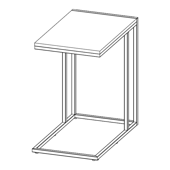
- Page 9 STEP 5 Assembly is now complete. PRINTED IN VIETNAM Page 8 of 8...
Need help?
Do you have a question about the BORDO Avon Lake 12101 and is the answer not in the manual?
Questions and answers
I need to purchase a replacement USB C outlet for the Broyhill Avon Lake “C” table due to cord damage