Table of Contents
Advertisement
Quick Links
Advertisement
Table of Contents

Subscribe to Our Youtube Channel
Related Manuals for Mindeo FS380


Summary of Contents for Mindeo FS380
- Page 1 FS380 Fixed Barcode Scanner User Manual Version: FS380_UM_EN_V1.2.4...
- Page 3 Notice Make sure you carefully read the following information to ensure that your barcode scanner is able to perform at the level for which it is designed. All software, including firmware, furnished to the user is on a licensed basis. The right is reserved to make changes to any software or product to improve reliability, function, or design.
-
Page 5: Table Of Contents
Contents Notice................................i Contents ..............................iii Technical specifications ..........................1 Pin assignment ............................2 Default setting for each barcode ........................ 3 Decode zone .............................. 4 Dimensions ..............................5 Parts of the scanner ........................... 6 Introduction to installation........................... 7 Scanning ..............................9 Programming instruction .......................... - Page 6 GS1 DataBar Limited ..........................44 GS1 DataBar Expanded ........................... 45 G1-G6 & FN1 substitution string setting ....................47 G1-G4 string position & Code ID position ....................50 String transmission ........................... 51 Test Chart ..............................53 Troubleshooting ............................55 Maintenance ............................. 56 Barcode representing non-printable character..................
-
Page 7: Technical Specifications
Technical specifications 5 VDC ± 0.25V Input voltage Power 425 mW (Operating); 500 mW (Max.) Current 85 mA (Operating); 100 mA (Max.) <250μA Standby current Laser 650nm laser diode 200 times/sec Decoding rate Scanning angle ± 60° , ± 65° , ± 42° (Skew, Pitch, Roll) UPC-A, UPC-E, EAN-13, EAN-8, ISBN/ISSN, Code 39, Code 39 full ASCII, Code 32(Italian pharmacy, a variant of code 39), Trioptic Code 39, Interleaved 2 of 5, Industrial 2 of 5, Matrix 2 of 5, Codabar(NW7), Code 128, Code 93, Code... -
Page 8: Pin Assignment
Pin assignment Pin 10 BEEP Pin 1 RS232 Power (+5V) Power (+5V) +3.3V ( for interface auto selection purpose) +3.3V ( for interface auto selection purpose) Ground Ground +3.3V ( for interface auto selection purpose) Ground (for interface auto selection purpose) Reserved Reserved Reserved... -
Page 9: Default Setting For Each Barcode
Default setting for each barcode Read Check digit Check digit Minimal Proprietary Code type enable verification transmission code length code ID code ID √ √ √ UPC-A (12) √ √ √ UPC-E EAN-13 √ √ √ (13) √ √ √ EAN-8 √... -
Page 10: Decode Zone
Decode zone High-density series Long-range series... -
Page 11: Dimensions
Dimensions... -
Page 12: Parts Of The Scanner
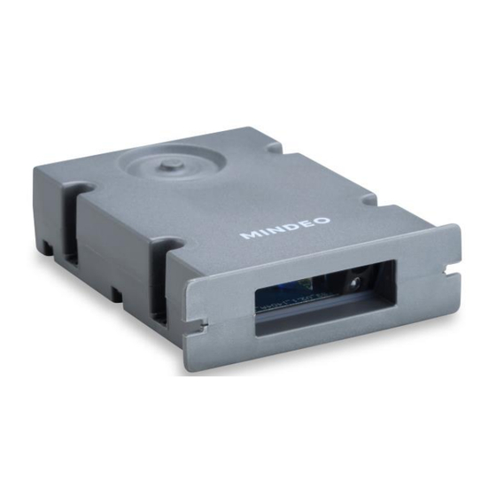
Parts of the scanner ① Button ② Exit window... -
Page 13: Introduction To Installation
Introduction to installation Note: If any of the below operation is incorrect, turn off the power immediately and check the scanner for any improper connections. Go through all steps again. Installation - with USB cable 1. Plug the USB cable into the USB port of the computer. 2. - Page 14 Note that the PS2 cable can be replaced by USB cable, as shown in below. The installation guide please refer to the description of “Installation –USB cable” in this chapter.
-
Page 15: Scanning
Scanning When the scanner is scanning, ensure the scan line crosses every bar and space of the symbol. RIGHT WRONG... -
Page 16: Programming Instruction
Programming instruction Refer to the next page, the steps of programming are: 1. Scan the SETUP bar code on the parameter setting part. 2. Enter the option mode by scanning the Option bar code. 3. To the right of the option barcode, the necessary alphanumeric inputs are listed. Scan these alphanumeric entries from the back foldout page. -
Page 17: Operate The Scanner By Receiving Command Via Uart
Operate the scanner by receiving command via UART Note: 1- The information in this chapter is provided for the scanner with RS232 cable or USB cable. 2- If the scanner is with USB cable, the setting of USB device type must be set as “USB virtual COM”. Please refer to chapter of “USB interface”. -
Page 18: Keyboard Wedge
Keyboard wedge Keyboard type: As a keyboard interface, the scanner supports most of the popular PCs and IBM terminals. Keyboard layout: The scanner supports different national keyboard layouts. Clock period: According to the PS2 protocol, the clock is provided by the device, e.g. keyboard or scanner, with the period between 60us to 100us. - Page 19 SETUP Option bar code Option Alpha. entry Slovak Denmark Japanese 60us 70us Clock period 80us 90us 100us 200us 10ms Delay-after-compound-key 20ms 40ms 80ms Alphabetic key Numeric key Numeric keypad Alt+ keypad Power-on simulation Disable Enable Inter-character delay 10ms 20ms 40ms 80ms Inter-byte delay Caps Lock status...
-
Page 20: Rs-232 Interface
RS-232 interface Flow control: None-The communication only uses TxD and RxD signals without any hardware or software handshaking protocol. RTS/CTS-If the scanner wants to send the barcode data to host computer, it will issue the RTS signal first, wait for the CTS signal from the host computer, and then perform the normal data communication. If there is no replied CTS signal from the host computer after the timeout duration, the scanner will issue an error indication. - Page 21 SETUP Option bar code Option Alpha. entry None Flow control RTS/CTS (Host idle: Low RTS) RTS/CTS (Host idle: High RTS) XON/XOFF ACK/NAK Inter-character delay 10ms 20ms 40ms 80ms Reserved Response delay 00-99 (100ms) 00-99 Baud rate 1200 2400 4800 9600 19200 38400 57600...
-
Page 22: Usb Interface
USB interface USB device type: HID keyboard– By setting, the scanner is used as a USB HID keyboard emulation device. keyboard layout setting follows the setting of keyboard layout in the chapter of Keyboard wedge. USB virtual COM– By setting, the scanner is used as a USB virtual COM emulation device. A software driver is required to install on the connected PC. -
Page 23: Indication Of Decode Success
Indication of decode success Power on alert: After power-on the scanner will generate an alert signal to indicate a successful self-test. Beeper indication: After each successful reading, the scanner will beep to indicate a good barcode reading, and its beep tone duration is adjustable. Return message indication: By enable, the scanner will transmit “NoRead”... -
Page 24: Scanning & Some Global Settings
Scanning & some global settings Scanning mode: Single scan-The trigger button must be pressed once to activate scanning. The light source of scanner stops scanning when there is a successful reading or no code is decoded after the Stand-by duration elapsed. - Page 25 SETUP Alpha. Option bar code Option entry Single scan Scanning mode※ Continue scan Auto-detection Standby duration 00-99 (second) 00-99 Same barcode delay time 00-99 (50ms) 00-99 Double confirm 00-09 00-09 (00: no ) Global max. code length 04-99 04-99 Global min. code length 01-99 01-99 Global insert group selection...
-
Page 26: Upc-A
UPC-A Read: Format Leading zero Data digits (11 digits) Check digit Check digit verification: The check digit is optional. Check digit trans.: By setting Enable, check digit will be transmitted. Code ID setting: Code ID is a one-or-two-character string used to represent the symbol upon a succeeding reading. -
Page 27: Upc-E
UPC-E Read: Format Leading zero Data digits (6 digits) Check digits Check digit verification: The check digit is optional and made as the sum of the numerical value of the data digits. Check digit trans.: By setting Enable, check digit will be transmitted. Code ID setting: Refer to Code ID setting of UPC-A. -
Page 28: Upc-E1
UPC-E1 Read: Format System character “1” Data digits (6 digits) Check digits Check digit verification: The check digit verification is optional. Check digit trans.: By setting Enable, check digit will be transmitted. Code ID setting: Refer to Code ID setting of UPC-A. Insertion group selection: Refer to Insertion group selection of UPC-A. -
Page 29: Ean-13
SETUP Option barcode Option Alpha. entry Read Disable Enable Check digit verification Disable Enable Check digit trans. Disable Enable Code ID setting 00-FF 00-FF (ASCII) <D>* Insert group selection 00-66 00-66 None Supplement digits 2 digits 5 digits 2 or 5 digits None Truncation/Expansion Expand to EAN-13... - Page 30 EAN-13 Read: Format Data digits (12 digits) Check digit Check digit verification: The check digit is optional and made as the sum of the numerical value of the data digits. Check digit transmission: By setting Enable, check digit will be transmitted. Code ID setting: Refer to Code ID setting of UPC-A.
-
Page 31: Ean-8
EAN-8 Read: Format Data digits (7 digits) Check digit Check digit verification: The check digit is optional and made as the sum of the numerical value of the data digits. Check digit trans.: By setting Enable, check digit will be transmitted. Code ID setting: Refer to Code ID setting of UPC-A. -
Page 32: Code 39
Code 39 Read: Format ⋆ Data digits (variable) Check digit (optional) ⋆ Check digit verification: The check digit is optional and made as the sum module 43 of the numerical value of the data digits. Check digit transmission: By setting Enable, check digit will be transmitted. Max./Min. - Page 33 SETUP Option bar code Option Alpha. entry Read Disable Enable Check digit verification Disable Enable Check digit transmission Disable Enable Max. code length 00-99 00-99 Min. code length 00-99 00-99 Code ID setting 00-FF 00-FF (ASCII) <M>* Insert group selection 00-66 00-66 Format...
-
Page 34: Interleaved 2 Of 5
Interleaved 2 of 5 Read: Format Data digits (Variable) Check digit (optional) Check digit verification: The check digit is made as the sum module 10 of the numerical values of all data digits. There are two optional check digit algorithms: the specified Uniform Symbology Specification (USS) and the Optical Product Code Council (OPCC). -
Page 35: Industrial 2 Of 5
Industrial 2 of 5 Read: Format Data digits (variable) Check digit (optional) Max./Min. code length: Refer to Max./Min. code length of Code 39. Code ID setting: Refer to Code ID setting of UPC-A. Insertion group selection: Refer to Insertion group selection of UPC-A. SETUP Option bar code Option... -
Page 36: Matrix 2 Of 5
Matrix 2 of 5 Read: Format Data digits (variable) Check digit (optional) Check digit verification: The check digit is made as the sum module 10 of the numerical values of all data digits. Check digit transmission: By setting Enable, check digit will be transmitted. Max./Min. -
Page 37: Codabar
Codabar Read: Format Start Data digits (variable) Check digit (optional) Check digit verification: The check digit is made as the sum module 16 of the numerical values of all data digits. Check digit transmission: By setting Enable, check digit will be transmitted. Max./Min. -
Page 38: Code 128
Code 128 Read: Format Data digits (variable) Check digit (optional) Check digit verification: The check digit is made as the sum module 103 of all data digits. Check digit transmission: By setting Enable, check digit will be transmitted. Max./Min. code length: Refer to Max./Min. code length of Code 39. Code ID setting: Refer to Code ID setting of UPC-A. -
Page 39: Ucc/Ean 128
UCC/EAN 128 Read: Format Data digits (variable) Check digit (optional) Check digit verification: The check digit is made as the sum module 103 of all data digits. Check digit transmission: By setting Enable, check digit will be transmitted. Max. /Min. code length: Refer to Max./Min. code length of Code 39. Code ID setting: Refer to Code ID setting of UPC-A. -
Page 40: Isbt 128
ISBT 128 Read: Format “=” or “&” Data digits (variable) Check digit (optional) Check digit verification: The check digit verification is optional. Check digit transmission: By setting Enable, check digit will be transmitted. Max./Min. code length: Refer to Max./Min. code length of Code 39. Code ID setting: Refer to Code ID setting of UPC-A. - Page 41 SETUP Option barcode Option Alpha. entry Read Disable Enable Check digit verification Disable Enable Check digit transmission Disable Reserved Max. code length 00-99 00-99 Min. code length 00-99 00-99 Code ID setting 00- FF 00-FF (ASCII) <K>* Insert group selection 00-66 00-66...
-
Page 42: Code 93
Code 93 Read: Format Data digits (variable) 2 check digits (optional) Check digit verification: The check digit is made as the sum module 47 of the numerical values of all data digits. Check digit transmission: By setting Enable, check digit will be transmitted. Max./Min. -
Page 43: Code 11
Code 11 Read: Format Data digits (variable) Check digit 1 (optional ) Check digit 2 (optional) Check digit verification: The check digit is presented as the sum module 11 of all data digits. Check digit transmission: By setting Enable, check digit 1 and check digit 2 will be transmitted upon your selected check digit verification method. -
Page 44: Msi/Plessey
MSI/Plessey Read: Format Data digits (variable) Check digit 1 (optional) Check digit 2 (optional) Check digit verification: The MSI/Plessey has one or two optional check digits. There are three methods of verifying check digits, i.e. Mod10, Mod10/10 and Mod 11/10. The check digit 1 and check digit 2 will be calculated as the sum module 10 or 11 of the data digits. -
Page 45: Uk/Plessey
UK/Plessey Read: Format Data digits (variable) 2 check digits (optional) Check digit verification: The UK/Plessey has one or two optional check digits. The check digit 1 and check digit 2 will be calculated as the sum module 10 or 11 of the data digits. Check digit transmission: By setting Enable, check digit will be transmitted. -
Page 46: China Post
China Post Read: Format 11 Data digits Code ID setting: Refer to Code ID setting of UPC-A. Insertion group selection: Refer to Insertion group selection of UPC-A. SETUP Option bar code Option Alpha. entry Read Disable Enable Reserved Reserved Reserved Reserved Code ID setting 00-FF... -
Page 47: China Finance
China Finance Note: This type of barcode is not Omni-directionally decodable. The encodable character set includes numeric 0 to 9. Among the symbol of 0 to 9, 0 and 2, 4 and 9, 5 and 8, 6 and 7, have the symmetrical pattern;... - Page 48 SETUP Option bar code Option Alpha. entry Read Disable Enable Max. code length 00-99 00-99 Min. code length 00-99 00-99 Check digit verification Disable Reserved Disable Enable Leading character 5/6/7/8/9 Only 5 converted to A converted to A/B/C/D/E Only 6 converted to B Only 7 converted to C Only 8 converted to D Only 9 converted to E...
-
Page 49: Gs1 Databar (Gs1 Databar Truncated)
GS1 DataBar (GS1 DataBar Truncated) GS1 DataBar Truncated is structured and encoded the same as the standard GS1 DataBar format, except its height is reduced to a 13 modules minimum; while GS1 DataBar should have a height greater than or equal to 33 modules. Read: Format 16 Data digits... -
Page 50: Gs1 Databar Limited
GS1 DataBar Limited Read: Format 16 Data digits Code ID setting: Refer to Code ID setting of UPC-A. Insertion group selection: Refer to Insertion group selection of UPC-A. Conversion: Refer to Conversion of GS1 DataBar (GS1 DataBar Truncated). SETUP Option bar code Option Alpha. -
Page 51: Gs1 Databar Expanded
GS1 DataBar Expanded Read: Format Data characters (variable) Code ID setting: Refer to Code ID setting of UPC-A. Insertion group selection: Refer to Insertion group selection of UPC-A. Conversion: UCC/EAN 128- Refer to Code ID transmission of String transmission, ]Cm will be identified as AIM ID. SETUP Option bar code Option... -
Page 53: G1-G6 & Fn1 Substitution String Setting
G1-G6 & FN1 substitution string setting Format of barcode data transmission Prefix Code name Preamble Code ID Code length Code data Code ID Postamble Suffix Suffix string setting: The <enter > key is represented in different ASCII when it is applied by different OS. For a Windows/DOS OS, <enter>... - Page 54 FN1 substitution string setting: The FN1 character (0x1D) in an UCC/EAN128 barcode, or a Code 128 barcode, or a GS1 DataBar barcode can be substituted with a defined string. Truncate leading G5 string setting: By setting, a defined leading character or string can be truncated. Also a single character can be un-defined.
- Page 55 SETUP Option bar code Option Alpha. entry Prefix string setting 0-22 characters 00-FF None Suffix string setting 0-22 characters 00-FF <ENTER> 0A0D* Preamble string setting 0-22 characters 00-FF None Postamble string setting 0-22 characters 00-FF None Insert G1 string setting 0-22 characters 00-FF None...
-
Page 56: G1-G4 String Position & Code Id Position
G1-G4 string position & Code ID position Format of barcode data transmission Prefix Code name Preamble Code ID Code length Code data Code ID Postamble Suffix Insert G1/G2/G3/G4 string position: The scanner offers 4 positions to insert strings among the symbol. In case of the insertion position is greater than the length of the symbol, the insertion of string is not effective. -
Page 57: String Transmission
String transmission Note: The information in this chapter is closely related to the chapter of String setting. Format of barcode data transmission Prefix Code name Preamble Code ID Code length Code data Code ID Postamble Suffix Preamble transmission: By setting Enable, preamble will be appended before the data transmitted. Postamble transmission: By setting Enable, postamble will be appended after the data is transmitted. - Page 58 SETUP Option bar code Option Alpha. entry Prefix transmission Disable Enable Suffix transmission Disable Enable Code name transmission Disable Enable Preamble transmission Disable Enable Postamble transmission Disable Enable Code ID transmission Disable Proprietary ID AIM ID Code length transmission Disable Enable Case conversion Disable...
-
Page 59: Test Chart
Test Chart UPC-A UPC-E UPC-E1 EAN-8 EAN-13 Code 39 Code 32 A908765439 Interleaved 2 of 5 Industrial 2 of 5 (Default setting: Read disable) Matrix 2 of 5 Code 93 Code 11 (Default setting: Read disable) - Page 60 Test Chart (Continued) Code 128 UCC/EAN 128 ISBT 128 MSI/Plessey (Default setting: Read disable) UK/Plessey ISBN/ISSN China Post GS1 DataBar (GS1 DataBar Truncated) GS1 DataBar Limited GS1 DataBar Expanded...
-
Page 61: Troubleshooting
Troubleshooting Problem Possible causes Possible solutions Nothing happens when you No power to the Check the system power. Ensure the power follow the operating scanner. supply is connected. instructions, or the scanner Incorrect cables. Use the original cables. displays erratic behavior. Connections are loose. -
Page 62: Maintenance
Maintenance Cleaning the exit window is the only maintenance required. A dirty window may affect scanning accuracy. Do not allow any abrasive material to touch the window. Remove any dirt particles with a damp cloth. Wipe the window using a tissue moistened with water. Do not spray water or other cleaning liquids directly into the window. - Page 63 ASCII Table for keyboard wedge for RS-232 Null Down Left Right PgUp PgDn Home Enter Insert Ctrl+ Delete Alt+ Notes: The 2nd and the 3rd columns above are used for keyboard wedge only. “ & ‘ < > Example: ASCII “A” = “41”.
-
Page 64: Barcode Representing Non-Printable Character
Barcode representing non-printable character Notes to make the following barcode: a) According to different barcode printing software, the method of printing following barcode is different. b) If using CODESOFT software, firstly read the information through “Help→Index→Code128→Special input syntax”. Also refer to ASCII table. For example, if we wish to make “F1” barcode, select “code128”, then select “CODE A”... -
Page 65: Return Default Parameters & Others
Return default parameters & others WARNING: Default value initialization If you wish to return the scanner to all the factory default settings, scan the barcode above. Firmware version list If you wish to display the firmware version, scan the barcode above. -
Page 66: Configuration Alphanumeric Entry Barcode
Configuration alphanumeric entry barcode To finish parameter setting, please scan the bar code below.
Need help?
Do you have a question about the FS380 and is the answer not in the manual?
Questions and answers