Table of Contents
Advertisement
Advertisement
Table of Contents

Related Manuals for Mindeo MD22xx


Summary of Contents for Mindeo MD22xx
- Page 1 MD22xx Barcode Scanner User Manual Version: MD22xx_UM_EN_V3.2.15...
- Page 3 The right is reserved to make changes to any software or product to improve reliability, function, or design. The material in this manual is subject to change without notice. Please go to www.mindeo.cn latest service information. A standard packing includes a scanner, a PS2 cable and a CD (or a user manual). Accessories...
-
Page 5: Table Of Contents
Contents NOTICE ............................i Contents ............................iii 1 Specifications ..........................1 1-1 Technical specifications ........................1 1-2 Default setting for each barcode ...................... 1 1-3 Decode zone ............................ 2 2 Get Started ........................... 3 2-1 Cable connector pin-outs descriptions ..................... 3 2-2 Dimensions ............................ - Page 6 3-20 Code 128 ............................51 3-21 UCC/EAN 128 ..........................53 3-22 ISBT 128 ............................55 3-23 Code 93 ............................57 3-24 Code 11 ............................59 3-25 MSI/Plessey ..........................61 3-26 UK/Plessey ........................... 63 3-27 China Post ............................ 65 3-28 China Finance ..........................67 3-29 Telepen ............................
-
Page 7: Specifications
1 Specifications 1-1 Technical specifications Table 1-1 Technical specifications 5 VDC ± 0.25V Input voltage Power 500 mW (Operating); 650 mW (Max.) Current 100 mA (Operating); 130 mA (Max.) <250μA Standby current Laser 645-660nm laser diode 200 times/sec Decoding rate ±... -
Page 8: Default Setting For Each Barcode
1-2 Default setting for each barcode Table 1-2 Default setting for each barcode Min. code Read Check digit Check digit Proprietary Code type length enable verification transmission code ID code ID √ √ √ UPC-A (12) √ √ √ UPC-E √... -
Page 9: Decode Zone
1-3 Decode zone Figure 1-1 High-density series Figure 1-2 Long-range series... -
Page 10: Get Started
2 Get Started 2-1 Cable connector pin-outs descriptions Figure 2-1 Cable connector interface pin-outs The pin-outs descriptions in Table 2-1 apply to the cable connector on the scanner and are for reference only. Table 2-1 Cable connector pin-outs descriptions RS232 Keyboard (PS2) Power (+5V) Power (+5V) -
Page 11: Dimensions
2-2 Dimensions Figure 2-2 Dimensions of scanner... -
Page 12: Parts Of The Scanner
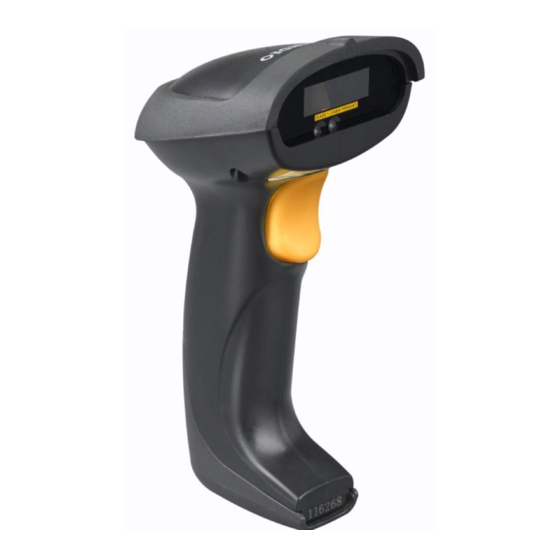
2-3 Parts of the scanner Figure 2-3 ① LED ② Exit window ③ Trigger ④ Cable interface port ⑤ Release-hole of the cable ⑥ Beeper... -
Page 13: Introduction To Installation
2-4 Introduction to installation Note: If any of the below operation is incorrect, turn off the power immediately and check the scanner for any improper connections. Go through all steps again. 2-4-1 Installation - keyboard wedge 1. Switch off the host and unplug the keyboard connector. 2. -
Page 14: Installation - Usb
2-4-3 Installation - USB The scanner attaches directly to a USB host, and is powered by it. No additional power supply is required. Refer to Figure 7-3, connect the USB interface cable to the bottom of the scanner. Plug the series A connector in the USB host, or an available port of the terminal. Windows will automatically detect the USB device. -
Page 15: Scanning
2-5 Scanning The scanner has two scanning modes: hand-held and auto-detection. When the scanner is scanning, ensure the scan line crosses every bar and space of the symbol. RIGHT WRONG Figure 2-8 2-6 Auto-detection The auto-detection scanning mode has two operating modes: in-stand and always ON. The following is an introduction to in-stand auto-detection mode. -
Page 16: Parameter Menus
3 Parameter menus 3-1 Example: configure scanner Important notes: 1. After each successful programming, the scanner will beep twice. 2. Throughout the programming barcode menus, the factory default settings are indicated with asterisks (*). 3. During the process of programming, LED is lighting to indicate the programming correctness. LED will go off if any incorrect programming operation performed. - Page 17 SETUP bar code Single-scan setting SETUP Option bar code Option Alpha. entry Single-scan setting None RTS/CTS (Host: Low RTS) Flow control RTS/CTS (Host: High RTS) XON/XOFF ACK/NAK Inter-character delay Option bar code Alpha. entries END bar code...
-
Page 18: Operate The Scanner By Receiving Command Via Uart
3-2 Operate the scanner by receiving command via UART Note The information in this chapter is provided for the scanner with RS232 cable or USB cable. If the scanner is with USB cable, the setting of USB device type must be set as “USB virtual COM”. 3-6 USB interface Please refer to chapter of 3-7 Scan mode &... -
Page 19: Interface Selection
3-3 Interface selection This scanner supports interfaces such as keyboard wedge, RS-232 serial wedge, and USB interface. In most of the cases, simply selecting an appropriate cable provided by the manufacturer will work for a specific interface. Interface selection: Auto detection-By setting this function, the scanner will automatically detect the keyboard wedge, RS-232 or USB interface for user. -
Page 20: Keyboard Wedge Interface
3-4 Keyboard wedge interface Keyboard type: As a keyboard interface, the scanner supports most of the popular PCs and IBM terminals. Keyboard layout: The scanner supports different national keyboard layouts. Clock period: According to the PS2 protocol, the clock is provided by the device, e.g. keyboard or scanner, with the period between 60us to 100us. - Page 21 SETUP Option bar code Option Alpha. entry Single-scan setting IBM AT, PS/2 Keyboard type Apple Mac compatibles Turkish F Turkish Q French Italian Spanish Keyboard layout Slovak Denmark Japanese German Belgian Russian 60us 70us Clock period 80us 90us 100us...
- Page 22 SETUP Option bar code Option Alpha. entry Single-scan setting 200us 10ms Delay-after-compound-key 20ms 40ms 80ms Alphabetic key Numeric key Numeric keypad Alt+ keypad Disable Power-on simulation Enable 10ms Inter-character delay 20ms 40ms 80ms Inter-byte delay...
- Page 23 SETUP Option bar code Option Alpha. entry Single-scan setting Disable Caps Lock reversion Enable Disable Caps Lock override Enable...
-
Page 24: Rs-232 Interface
3-5 RS-232 interface Host type: Standard- The scanner is connected to a standard RS-232 interface. OPOS/JPOS- The scanner is connected to a POS terminal which may be necessary to install the OPOS/JPOS driver to be compatible with the manufacturer's scanner. The OPOS/JPOS driver is provided by the scanner manufacturer;... - Page 25 SETUP Option bar code Option Alpha. entry Single-scan setting Standard Host type OPOS/JPOS None RTS/CTS (Host idle: Low RTS) Flow control RTS/CTS (Host idle: High RTS) XON/XOFF ACK/NAK 10ms Inter-character delay 20ms 40ms 80ms Reserved 01-99 Response delay 01-99 (100ms) Baud rate 1200...
- Page 26 2400 4800 9600 19200 38400 57600 115200 None Parity Even 8 bits Data bit 7 bits One bit Stop bit Two bits...
-
Page 27: Usb Interface
3-6 USB interface USB device type: HID keyboard– By setting, the scanner is used as a USB HID keyboard emulation device. The keyboard layout setting follows the setting of keyboard layout in the chapter of Keyboard wedge. USB virtual COM– By setting, the scanner emulate a regular RS232-based COM port. If a Microsoft Windows PC is connected to the scanner, a driver is required to install on the connected PC. - Page 28 SETUP Option bar code Option Alpha. entry Single-scan setting HID keyboard HID keyboard for Apple Mac USB device type USB virtual COM HID for OPOS/JPOS Turkish F Turkish Q French Italian Spanish Keyboard layout Slovak Denmark Japanese German Belgian Russian Inter-character delay 10ms...
- Page 29 SETUP Option bar code Option Alpha. entry Single-scan setting 20ms 40ms 60ms Alphabetic key Numeric key Numeric keypad Alt+ keypad...
-
Page 30: Scan Mode & Some Global Settings
3-7 Scan mode & some global settings Scan mode: Good-read off-The trigger button must be pressed once to activate scanning. The light source of scanner stops scanning when there is a successful reading or no code is decoded after the Stand-by duration elapsed. - Page 31 Character output restraint: Printable character only- If this option is selected, the scanner will output the printable characters only, i.e. in ASCII from 20H to 7EH. Alphanumeric character only- If this option is selected, the scanner will output the alphanumeric characters only, i.e.
- Page 32 SETUP Option bar code Option Alpha. entry Single-scan setting Good-read off Momentary Scan mode Alternate Continue Timeout off 01-99 Standby duration 01-99 (second) 00-FF Same barcode delay time 00-FF (50ms) 00-09 Double confirm 00-09 (00: no ) 04-99 Global max. code length 04-99 01-99 Global min.
- Page 33 SETUP Option bar code Option Alpha. entry Single-scan setting Enable None Character output restraint Printable character only Alphanumeric character only Disable Decoder optimization Enable Data output delay 00-FF 00-FF (100ms) in continue-scan mode FF (Never) 15 min 30 min Enter sleeping-mode delay 60 min Never Reserved...
-
Page 34: Indication
3-8 Indication Power on alert: After power-on the scanner will generate an alert signal to indicate a successful self-test. LED indication: After each successful reading, the LED above the scanner will light up to indicate a good barcode reading. Beeper indication: After each successful reading, the scanner will beep to indicate a good barcode reading, and its beep tone duration is adjustable. -
Page 35: Auto-Detection Setting
3-9 Auto-detection setting Auto-detect sensor: By setting Enable, the scanner will start operating if any nearby object has been detected. The laser light of scanner stops scanning when there is a successful reading or no code is decoded after the Stand-by duration elapsed. Once the laser light stops scanning, the present object must be removed to enable Auto-detect sensor. -
Page 36: Upc-A
3-10 UPC-A Read: Format System character Data digits (10 digits) Check digit (1 digit) Check digit verification: The check digit verification is optional. Check digit trans.: By setting Enable, check digit will be transmitted. Code ID setting: Code ID is a one-or-two-character string used to represent the symbol upon a succeeding reading. - Page 37 SETUP Option bar code Option Alpha. entry Single-scan setting 00-FF Code ID setting 00-FF (ASCII) <A>* 00-44 Insert group selection 00-44 None 2 digits Supplement digits 5 digits 2 or 5 digits None Truncate leading zeros Truncation/Expansion Expand to EAN-13 Truncate system character Add country code Reserved...
-
Page 38: Upc-E
3-11 UPC-E Read: Format System character “0” Data digits (6 digits) Check digits (1 digit) Check digit verification: The check digit verification is optional and made as the sum of the numerical value of the data digits. Check digit trans.: By setting Enable, check digit will be transmitted. 3-10 UPC-A Code ID setting: Refer to Code ID setting of 3-10 UPC-A... - Page 39 SETUP Option bar code Option Alpha. entry Single-scan setting 00-FF Code ID setting 00-FF (ASCII) <D>* 00-44 Insert group selection 00-44 None 2 digits Supplement digits 5 digits 2 or 5 digits None Truncate leading zeros Expand to EAN-13 Truncation/Expansion Expand to UPC-A Truncate system character Add country code...
-
Page 40: Upc-E1
3-12 UPC-E1 Read: Format System character “1” Data digits (6 digits) Check digits (1 digit) Check digit verification: The check digit is optional and made as the sum of the numerical value of the data digits. Check digit trans.: By setting Enable, check digit will be transmitted. 3-10 UPC-A Code ID setting: Refer to Code ID setting of 3-10 UPC-A... - Page 41 SETUP Option bar code Option Alpha. entry Single-scan setting 00-FF Code ID setting 00-FF (ASCII) <D>* 00-44 Insert group selection 00-44 None 2 digits Supplement digits 5 digits 2 or 5 digits None Reserved Expand to EAN-13 Truncation/Expansion Expand to UPC-A Truncate system character Add country code Reserved...
-
Page 42: Ean-13 (Isbn/Issn)
3-13 EAN-13 (ISBN/ISSN) Read: Format Data digits (12 digits) Check digit (1 digit) Check digit verification: The check digit is optional and made as the sum of the numerical value of the data digits. Check digit transmission: By setting Enable, check digit will be transmitted. 3-10 UPC-A EAN-13 code ID setting: Refer to Code ID setting of 3-10 UPC-A... - Page 43 SETUP Single-scan setting Option bar code Option Alpha. entry Disable Read Enable Disable Check digit verification Enable Disable Check digit transmission Enable 00-FF EAN-13 code ID setting 00-FF (ASCII) <A>* 00-44 Insert group selection 00-44 None 2 digits Supplement digits 5 digits 2 or 5 digits...
- Page 44 SETUP Single-scan setting Option bar code Option Alpha. entry Disable ISBN/ISSN conversion Enable 00-FF ISBN/ISSN code ID setting 00-FF (ASCII) <B>*...
-
Page 45: Ean-8
3-14 EAN-8 Read: Format Data digits (7 digits) Check digit (1 digit) Check digit verification: The check digit is optional and made as the sum of the numerical value of the data digits. Check digit trans.: By setting Enable, check digit will be transmitted. 3-10 UPC-A Code ID setting: Refer to Code ID setting of 3-10 UPC-A... - Page 46 SETUP Single-scan setting Option bar code Option Alpha. entry None 2 digits Supplement digits 5 digits 2 or 5 digits None Truncation/Expansion Truncate leading zero Expand to EAN-13 Reserved...
-
Page 47: Code 39 (Code 32, Trioptic Code 39)
3-15 Code 39 (Code 32, Trioptic Code 39) Read: Format Start character (*) Data digits (variable) Check digit (optional) End character (*) Check digit verification: The check digit is optional and made as the sum module 43 of the numerical value of the data digits. - Page 48 SETUP Single-scan setting Option bar code Option Alpha. entry Disable Read Enable Disable Check digit verification Enable Disable Check digit transmission Enable 00-99 Max. code length 00-99 00-99 Min. code length 00-99 00-FF Code ID setting 00-FF (ASCII) <M>* 00-44 Insert group selection 00-44 Standard...
- Page 49 SETUP Single-scan setting Option bar code Option Alpha. entry Enable Disable Convert Code 39 to Code 32 Enable Disable Code 32 Prefix “A” transmission Enable Disable Trioptic Code 39 read Enable Disable Trioptic Code 39 Start/End transmission Enable Note 1: If Trioptic Code 39 is set Enable, Code 39 is forced Enable. Note 2: If Code 39 is set Disable, Trioptic Code 39 is forced Disable.
-
Page 50: Interleaved 2 Of 5
3-16 Interleaved 2 of 5 Read: Format Data digits (Variable) Check digit (optional) Check digit verification: The check digit is made as the sum module 10 of the numerical values of all data digits. There are two optional check digit algorithms: the specified Uniform Symbol Specification (USS) and the Optical Product Code Council (OPCC). - Page 51 SETUP Single-scan setting Option bar code Option Alpha. entry Disable Read Enable Disable Check digit verification OPCC Disable Check digit transmission Enable 00-99 Max. code length 00-99 00-99 Min. code length 00-99 00-FF Code ID setting 00-FF (ASCII) <I>* 00-44 Insert group selection 00-44 Reserved...
-
Page 52: Industrial 2 Of 5 (Discrete 2 Of 5)
3-17 Industrial 2 of 5 (Discrete 2 of 5) Read: Format Data digits (variable) 3-15 Code 39 (Code 32, Trioptic Code 39) Max./Min. code length: Refer to Max./Min. code length of 3-10 UPC-A Code ID setting: Refer to Code ID setting of 3-10 UPC-A Insertion group selection: Refer to Insertion group selection of SETUP... -
Page 53: Matrix 2 Of 5
3-18 Matrix 2 of 5 Read: Format Data digits (variable) Check digit (optional) Check digit verification: The check digit is made as the sum module 10 of the numerical values of all data digits. Check digit transmission: By setting Enable, check digit will be transmitted. 3-15 Code 39 (Code 32, Trioptic Code 39) Max./Min. - Page 54 SETUP Single-scan setting Option bar code Option Alpha. entry Disable Read Enable Disable Check digit verification Enable Disable Check digit transmission Enable 00-99 Max. code length 00-99 00-99 Min. code length 00-99 00-FF Code ID setting 00-FF (ASCII) <X>* 00-44 Insert group selection 00-44 Reserved...
-
Page 55: Codabar
3-19 Codabar Read: Format Start Data digits (variable) Check digit (optional) Check digit verification: The check digit is made as the sum module 16 of the numerical values of all data digits. Check digit transmission: By setting Enable, check digit will be transmitted. 3-15 Code 39 (Code 32, Trioptic Code 39) Max./Min. - Page 56 SETUP Single-scan setting Option bar code Option Alpha. entry Disable Read Enable Disable Check digit verification Enable Disable Check digit transmission Enable 00-99 Max. code length 00-99 00-99 Min. code length 00-99 00-FF Code ID setting 00-FF (ASCII) <N>* 00-44 Insert group selection 00-44 ABCD/ABCD...
- Page 57 SETUP Single-scan setting Option bar code Option Alpha. entry abcd/tn*e Disable Start/End transmission Enable Disable Start/End character equality Enable...
-
Page 58: Code 128
3-20 Code 128 Read: Format Data digits (variable) Check digit (optional) Check digit verification: The check digit is made as the sum module 103 of all data digits. Check digit transmission: By setting Enable, check digit will be transmitted. 3-15 Code 39 (Code 32, Trioptic Code 39) Max./Min. - Page 59 SETUP Single-scan setting Option bar code Option Alpha. entry Disable Read Enable Disable Check digit verification Enable Disable Check digit transmission Reserved 00-99 Max. code length 00-99 00-99 Min. code length 00-99 00-FF Code ID setting 00-FF (ASCII) <K>* 00-44 Insert group selection 00-44 Disable...
-
Page 60: Ucc/Ean 128
3-21 UCC/EAN 128 Read: Format Data digits (variable) Check digit (optional) Check digit verification: The check digit is made as the sum module 103 of all data digits. Check digit transmission: By setting Enable, check digit will be transmitted. 3-15 Code 39 (Code 32, Trioptic Code 39) Max. - Page 61 SETUP Single-scan setting Option bar code Option Alpha. entry Disable Read Enable Disable Check digit verification Enable Disable Check digit transmission Reserved 00-99 Max. code length 00-99 00-99 Min. code length 00-99 00-FF Code ID setting 00-FF (ASCII) <K>* 00-44 Insert group selection 00-44 Disable...
-
Page 62: Isbt 128
3-22 ISBT 128 Read: Format Start character (“=” or “&”) Data digits (variable) Check digit (optional) Check digit verification: The check digit is made as the sum module 103 of all data digits. Check digit transmission: By setting Enable, check digit will be transmitted. 3-15 Code 39 (Code 32, Trioptic Code 39) Max./Min. - Page 63 SETUP Option bar code Option Alpha. entry Single-scan setting Disable Read Enable Disable Check digit verification Enable Disable Check digit transmission Reserved 00-99 Max. code length 00-99 00-99 Min. code length 00-99 00-FF Code ID setting 00-FF (ASCII) <K>* 00-44 Insert group selection 00-44 Reserved...
-
Page 64: Code 93
3-23 Code 93 Read: Format Data digits (variable) 2 check digits (optional) Check digit verification: The check digit is made as the sum module 47 of the numerical values of all data digits. Check digit transmission: By setting Enable, check digit will be transmitted. 3-15 Code 39 (Code 32, Trioptic Code 39) Max./Min. - Page 65 SETUP Option bar code Option Alpha. entry Single-scan setting Disable Read Enable Disable Check digit verification Enable Disable Check digit transmission Enable 00-99 Max. code length 00-99 00-99 Min. code length 00-99 00-FF Code ID setting 00-FF (ASCII) <L>* 00-44 Insert group selection 00-44 Reserved...
-
Page 66: Code 11
3-24 Code 11 Read: Format Data digits (variable) Check digit 1 (optional ) Check digit 2 (optional) Check digit verification: The check digit is presented as the sum module 11 of all data digits. Check digit transmission: By setting Enable, check digit 1 and check digit 2 will be transmitted upon your selected check digit verification method. - Page 67 SETUP Option bar code Option Alpha. entry Single-scan setting Disable Read Enable Disable One digit Check digit verification Reserved Reserved Disable Check digit transmission Enable 00-99 Max. code length 00-99 00-99 Min. code length 00-99 00-FF Code ID setting 00-FF (ASCII) <V>* 00-44...
-
Page 68: Msi/Plessey
3-25 MSI/Plessey Read: Format Data digits (variable) Check digit 1 (optional) Check digit 2 (optional) Check digit verification: The MSI/Plessey has one or two optional check digits. There are three methods of verifying check digits, i.e. Mod10, Mod10/10 and Mod 11/10. The check digit 1 and check digit 2 will be calculated as the sum module 10 or 11 of the data digits. - Page 69 SETUP Option bar code Option Alpha. entry Single-scan setting Disable Read Enable Disable 1 digit (mod 10) Check digit verification Reserved Reserved Disable Check digit transmission Enable 00-99 Max. code length 00-99 00-99 Min. code length 00-99 00-FF Code ID setting 00-FF (ASCII) <O>*...
-
Page 70: Uk/Plessey
3-26 UK/Plessey Read: Format Data digits (variable) 2 check digits (optional) Check digit verification: The UK/Plessey has one or two optional check digits. The check digit 1 and check digit 2 will be calculated as the sum module 10 or 11 of the data digits. Check digit transmission: By setting Enable, check digit will be transmitted. - Page 71 SETUP Single-scan setting Option bar code Option Alpha. entry Disable Read Enable Disable Check digit verification Enable Disable Check digit transmission Enable 00-99 Max. code length 00-99 00-99 Min. code length 00-99 00-FF Code ID setting 00-FF (ASCII) <U>* 00-44 Insert group selection 00-44 Reserved...
-
Page 72: China Post
3-27 China Post Read: Format 11 Data digits 3-15 Code 39 (Code 32, Trioptic Code 39) Max. /Min. code length: Refer to Max./Min. code length of The code length of China Post is 11. 3-10 UPC-A Code ID setting: Refer to Code ID setting of 3-10 UPC-A Insertion group selection: Refer to Insertion group selection of... - Page 73 SETUP Option bar code Option Alpha. entry Single-scan setting Disable Read Enable Reserved Reserved 00-99 Max. code length 00-99 00-99 Min. code length 00-99 00-FF Code ID setting 00-FF (ASCII) <T>* 00-44 Insert group selection 00-44 Reserved...
-
Page 74: China Finance
3-28 China Finance Note: This type of barcode is not Omni-directionally decodable. The encodable character set includes numeric 0 to 9. Among the symbol of 0 to 9, 0 and 2, 4 and 9, 5 and 8, 6 and 7, have the symmetrical pattern;... - Page 75 SETUP Option bar code Option Alpha. entry Single-scan setting Disable Read Enable 00-99 Max. code length 00-99 00-99 Min. code length 00-99 Disable Check digit verification Reserved Disable Enable Only 5 converted to A Leading character 5/6/7/8/9 converted to A/B/C/D/E Only 6 converted to B Only 7 converted to C Only 8 converted to D...
- Page 76 SETUP Option bar code Option Alpha. entry Single-scan setting Assigned to 7(C) Assigned to 8(D) Assigned to 9(E) Assigned to 1 Assigned to 2 Assigned to 3 Assigned to 4 00-FF Code ID setting 00-FF (ASCII) <Y>* 00-44 Insert group selection 00-44 Laser Light Direction Setting: By scanning the barcode above, the decoding direction of the scanner’s laser light is from left to right.
-
Page 77: Telepen
3-29 Telepen Read: Format Start character (_) Data digits (variable) Check digit End character (z) Check digit verification: The check digit verification is optional. Check digit transmission: By setting Enable, check digit will be transmitted. 3-15 Code 39 (Code 32, Trioptic Code 39) Max./Min. - Page 78 SETUP Multiple-scan setting Single-scan setting Option barcode Option Alpha. entry Disable Read Enable Disable Check digit verification Enable Disable Check digit transmission Enable 00-99 Max. code length 00-99 00-99 Min. code length 00-99 00-FF Code ID setting 00-FF 00-66 Insertion group selection 00-66 Alphanumeric Encode character set type...
-
Page 79: Gs1 Databar (Gs1 Databar Truncated)
3-30 GS1 DataBar (GS1 DataBar Truncated) GS1 DataBar Truncated is structured and encoded the same as the standard GS1 DataBar format, except its height is reduced to a 13 modules minimum; while GS1 DataBar should have a height greater than or equal to 33 modules. Read: Format 16 Data digits... -
Page 80: Gs1 Databar Limited
3-31 GS1 DataBar Limited Read: Format 16 Data digits 3-10 UPC-A Code ID setting: Refer to Code ID setting of 3-10 UPC-A Insertion group selection: Refer to Insertion group selection of 3-30 GS1 DataBar (GS1 DataBar Truncated) Conversion: Refer to Conversion of SETUP Single-scan setting Option bar code... -
Page 81: Gs1 Databar Expanded
3-32 GS1 DataBar Expanded Read: Format Data characters (variable) 3-10 UPC-A Code ID setting: Refer to Code ID setting of 3-10 UPC-A Insertion group selection: Refer to Insertion group selection of Conversion: 3-35 String transmission UCC/EAN 128- Refer to Code ID transmission of , ]Cm will be identified as AIM ID. - Page 82 SETUP Option bar code Option Alpha. entry Single-scan setting Disable Read Enable 00-99 Max. code length 00-99 00-99 Min. code length 00-99 00-FF Code ID setting 00-FF (ASCII) <R >* 00-44 Insert group selection 00-44 None Conversion UCC/EAN 128 Reserved...
-
Page 83: G1-G4 & C1-C2 & Fn1 Substitution String Setting
3-33 G1-G4 & C1-C2 & FN1 substitution string setting Format of barcode data transmission Prefix Code name Preamble Code ID Code length Code data Code ID Postamble Suffix Suffix string setting: The <enter > key is represented in different ASCII when it is applied by different OS. For a Windows/DOS OS, <enter>... - Page 84 FN1 substitution string setting: The FN1 character (0x1D) in an UCC/EAN128 barcode, or a Code 128 barcode, or a GS1 DataBar barcode can be substituted with a defined string. Truncate leading G5 string setting: By setting, a defined leading character or string can be truncated. Also a single character can be un-defined.
- Page 85 SETUP Option bar code Option Alpha. entry Single-scan setting 0-22 characters 00-FF Prefix string setting None 0-22 characters 00-FF Suffix string setting <ENTER> 0D0A* 0-22 characters 00-FF Preamble string setting None 0-22 characters 00-FF Postamble string setting None 0-22 characters 00-FF Insert G1 string setting None...
- Page 86 SETUP Option bar code Option Alpha. entry Single-scan setting 1-22 defined characters 01-7F <0> Once Repeat of a G5 character setting Defined times 01-22 Un-defined times (All) A un-defined character Truncate ending G4 string setting 1-22 defined characters 01-7F <0> Once Repeat of a G4 character setting Defined times...
-
Page 87: G1-G4 String Position & Code Id Position
3-34 G1-G4 string position & Code ID position Format of barcode data transmission Prefix Code name Preamble Code ID Code length Code data Code ID Postamble Suffix Insert G1/G2/G3/G4 string position: The scanner offers 4 positions to insert strings among the symbol. In case of the insertion position is greater than the length of the symbol, the insertion of string is not effective. -
Page 88: String Transmission
3-35 String transmission Note: The information in this chapter is closely related to the chapter of String setting. Format of barcode data transmission Prefix Code name Preamble Code ID Code length Code data Code ID Postamble Suffix Prefix transmission: By setting Enable, prefix will be appended before the data transmitted. Suffix transmission: By setting Enable, suffix will be appended after the data is transmitted. - Page 89 SETUP Single-scan setting Option bar code Option Alpha. entry Disable Prefix transmission Enable Disable Suffix transmission Enable Disable Code name transmission Enable Disable Preamble transmission Enable Disable Postamble transmission Enable Disable Code ID transmission Proprietary ID AIM ID Disable Code length transmission Enable Disable Upper (data only)
- Page 90 SETUP Single-scan setting Option bar code Option Alpha. entry Lower (whole string) Disable Keyboard wedge/USB FN1 substitution transmission RS-232 Keyboard wedge/ USB/RS-232 All-non-printable-character string Disable transmission with string setting Enable Transmit the first N data characters only 01-99 01-99 Transmit the last N data characters only 01-99 01-99...
-
Page 91: Troubleshooting
4 Troubleshooting Problem Possible causes Possible solutions Check the system power. Ensure the Nothing happens when No power to the scanner. power supply is connected. follow the operating instructions, or the scanner displays erratic Incorrect cables. Use the original cables. behavior. -
Page 92: Maintenance
5 Maintenance Cleaning the exit window is the only maintenance required. A dirty window may affect scanning accuracy. Do not allow any abrasive material to touch the window. Remove any dirt particles with a damp cloth. Wipe the window using a tissue moistened with water. Do not spray water or other cleaning liquids directly into the window. -
Page 93: Assembling The Stand
6 Assembling the stand See the figure above, tighten the screws. Bend the neck to the desired position for scanning. Screw mounting: Screw one #10 wood screw into each screw-mount-hole until the base of the stand is secured. Tape mounting: ①Peel the paper liner off one side of each piece of tape and place the sticky surface over each of the three rectangular tape holders. -
Page 94: Barcode Representing Non-Printable Character
7 Barcode representing non-printable character Notes to make the following barcode: 1. According to different barcode printing software, the method of printing following barcode is different. 2. If using CODESOFT software, firstly read the information through “Help→Index→Code128→Special input syntax”. Also refer to ASCII table. For example, if we wish to make “F1” barcode, select “code128”, then select “CODE A”... -
Page 95: Ascii Table
8 ASCII Table for keyboard wedge for RS-232 Null Down Left Right PgUp PgDn Home Enter Insert Ctrl+ Delete Alt+ Notes: The 2nd and the 3rd columns above are used for keyboard wedge only. “ & ‘ < > Example: ASCII “A” = “41”. -
Page 96: Test Chart
9 Test Chart UPC-A UPC-E UPC-E1 EAN-13 ISBN/ISSN EAN-8 Code 39 Code 32 A908765439 Trioptic Code 39 (Default setting: Disable) Interleaved 2 of 5 Industrial 2 of 5 (Default setting: Disable) Matrix 2 of 5 Codabar... - Page 97 Test chart (continue) Code 128 UCC/EAN 128 ISBT 128 Code 93 Code 11 (Default setting: Disable) MSI/Plessey (Default setting: Disable) UK/Plessey China Post Telepen GS1 DataBar (GS1 DataBar Truncated) GS1 DataBar Limited GS1 DataBar Expanded...
-
Page 98: Return Default Parameters & Firmware Version List
10 Return default parameters & Firmware version list WARNING: Default value initialization If you wish to return the scanner to all the factory default settings, scan the barcode above. Firmware version list If you wish to display the firmware version, scan the barcode above. -
Page 99: Configuration Alphanumeric Entry Barcode
11 Configuration alphanumeric entry barcode To finish parameter setting, please scan the bar code below.
Need help?
Do you have a question about the MD22xx and is the answer not in the manual?
Questions and answers