Table of Contents
Advertisement
Advertisement
Table of Contents

Related Manuals for Mindeo CR40 Series


Summary of Contents for Mindeo CR40 Series
- Page 1 CR40 Bluetooth Ring Scanner User Manual Version: CR40_UM_EN_V1.1.1...
- Page 2 Notice CR40 is a Bluetooth Ring Scanner. Before operating scanner, please make sure you carefully read the following information to ensure that your scanner is able to perform at the level for which it is designed. All software, including firmware, furnished to the user is on a licensed basis. The right is reserved to make changes to any software or product to improve reliability, function, or design.
-
Page 3: Table Of Contents
Contents Notice ..............................i Contents ..............................ii 1 Specifications ............................. 1 1-1 Technical specifications ........................1 1-2 Default settings for each barcode ....................4 1-3 Dimensions ............................5 1-4 Parts of the scanner ......................... 5 2 Introduction to installation ........................6 2-1 Installing a USB HID keyboard wired scanner ................. - Page 4 4-14 Industrial 2 of 5 (Discrete 2 of 5) ....................41 4-15 Matrix 2 of 5 ..........................42 4-16 Codabar ............................43 4-17 Code 128 ............................45 4-18 UCC/EAN 128 ..........................47 4-19 ISBT 128 ............................49 4-20 Code 93 ............................50 4-21 Code 11 ............................
-
Page 5: Specifications
Specifications 1-1 Technical specifications CR40-1D CR40-2D Working range 30m(line of sight) Radio link 2.4GHz, Bluetooth 4.0, Class 1.5 Bluetooth: HID keyboard, SPP, GATT Interface Micro USB: USB HID keyboard, USB virtual COM 8KB for out of range batch: 6KB for out of range batch: 500 barcodes 375 barcodes (each barcode is of 15... - Page 6 Charging time approximately 1 hours Light source 650nm visible laser diode white light Image size 1280×800 pixels Scanning angle Horizontal:42°,vertical:26.5° ±50°,±65°,±35° ±70°,±72°,360° Scanning angle (Skew、Pitch、Roll) (Skew、Pitch、Roll) Scanning rate 100±10 times/second Barcode contrast minimum 20% UPC-A,UPC-E,EAN-13, EAN-8,ISBN/ISSN,Code 39,Code 39 full ASCII, 1D: UPC-A,...
- Page 7 working: -15°C to 50°C (5°F to 122°F) Temperature storage: -20°C to 60°C (-4°F to 140°F) Humidity 5% to 95%(non-condensing) Laser safety: EN60825-1,Class 1 EMC:EN55022,EN55024 Electrical safety: EN60950-1 Safety Illumination: 0~100,000LUX Protection class: IP50 Drop resistance: Multiple 1m(3.2ft)drops to concrete Environmental: RoHS compliant...
-
Page 8: Default Settings For Each Barcode
1-2 Default settings for each barcode Read Check digit Check digit Min.code Proprietary Code type enable verification transmission length code ID code ID UPC-A (12) √ √ √ UPC-E (8) √ √ √ UPC-E1 (8) √ √ EAN-13 (13) √ √... -
Page 9: Dimensions
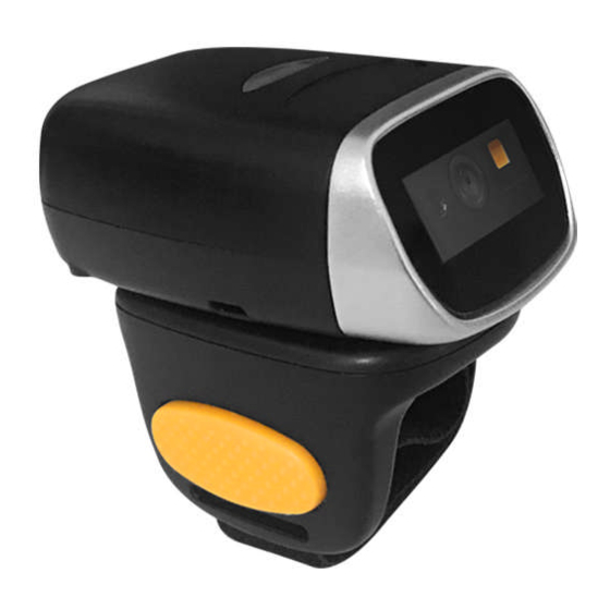
1-3 Dimensions Figure 1-1 Dimensions of the scanner 1-4 Parts of the scanner Figure 1-2 Parts of the scanner 1 LED ○ ○ 2 Scan window ○ 3 Ring strap ○ 4 Power switch 5 Micro USB port / Battery charging port ○... -
Page 10: Introduction To Installation
Introduction to installation 2-1 Installing a USB HID keyboard wired scanner Note: The default interface of the scanner is Bluetooth. Please change the Data Transfer to USB HID 3-4-2 USB HID Keyboard Keyboard Mode (See Refer to Figure 2-1, plug one end of the USB cable to the scanner. Plug the other end into the USB port of the computer. -
Page 11: Operations Of The Scanner
Operations of the scanner Note: 1. Please establish a Bluetooth in the range of the network before the first time of scanning barcodes. 2. The scanner can perform a barcode scan operation even though no Bluetooth network is available. However, the scanner may react in a way that differs from what is described here if no Bluetooth is working. -
Page 12: Data Transfer
stop scanning. The light source of scanner stops scanning when there is a successful reading or no code is decoded after the Stand-by duration elapsed. Continuous - The scanner always keeps scanning, and it does not matter when the trigger button is released or duration is elapsed. - Page 13 Data Transfer - Bluetooth Step 2: Scan the Bluetooth-HID barcode below. Bluetooth-HID Step 3: When a device that supports Bluetooth 4.0 is connected to the scanner, the LED on the top of the scanner will remain blue and the device will receive incoming data from the scanner. 3-4-1-2 Configure Bluetooth SPP profile communication Step 1: Scan the barcode below to setting bluetooth profile for data transfer.
-
Page 14: Usb Hid Keyboard
Data Transfer - Bluetooth Step 2: Scan the Bluetooth-BA2110 barcode below. Bluetooth - BA2110 Step 3: Plug a BA2110 into the USB port of the computer Step 4: Scan the barcode on the back of BA2110. Step 5: When the scanner pairs with BA2110,the LED on the top of the scanner will remain blue and the device will receive incoming data from the scanner. -
Page 15: Communication Setting
Send batch data - Data transmission is triggered by this menu command. Before undertaking this operation, make sure a communication link (Bluetooth network or USB cable) is working. Interfaces - There are three types of communication interfaces Bluetooth, USB HID keyboard and USB 3-4-1 Bluetooth virtual COM. -
Page 16: Indication
3-5 Indication The scanner contains LEDs on the top of the unit that indicate linking status,decoding state,and battery condition.The following table lists the LED indicators, beeps,and vibrations for the scanner. Table 3-2 Indication Cause LED Indication Beeper indication Vibrate indication No Bluetooth connection Blue flash None... -
Page 17: Barcode Programming Instructions
Barcode programming instructions 4-1 Example: Single-parameter setting by scanning 1D barcode Important notes: 1. During the process of programming, LED is lighting to indicate the programming correctness. LED will go off if any incorrect programming operation performed. 2. After each successful programming, LED will go off and the scanner will beep twice. 3. -
Page 18: Common Settings Of The Scanner
4-2 Common settings of the scanner Multiple-scan setting Single-scan setting Option barcode Option Alpha. Entry Bluetooth USB HID Keyboard Data Transfer USB Virtual COM Standard Batch Bluetooth GATT BA2110 Out-of-range batch Disable in Bluetooth Enable Auto reconnection Disable in Bluetooth Enable Inter-char delay in HID Bluetooth... - Page 19 Send batch data None None in Standard Batch Clear batch data None None in Standard Batch Disconnect Bluetooth None None Display Bluetooth name None None Example:MINDEO Change the name of Bluetooth None (Up to 12 characters) Display Bluetooth Mac address None None...
- Page 20 Multiple-scan setting Single-scan setting Option barcode Option Alpha. Entry Switching the virtual keyboard None None on Apple iOS...
-
Page 21: Scanning Mode And Some Global Settings
4-3 Scanning mode and some global settings Scanning mode: Good-read off -The trigger button must be pressed once to activate scanning. The light source of scanner stops scanning when there is a successful reading or no code is decoded after the Stand-by duration elapsed. - Page 22 Data output delay in continue-scan mode: If it is enabled, in the continue-scan mode, the scanner can store the data while continue-scanning. The scanner will output the data after the predefined delay elapsed. The maximum storage of data is 1000 characters. If this parameter is set to be “00”, the scanner will not store data.
- Page 23 Multiple-scan setting Single-scan setting Option barcode Option Alpha. entry Good-read off Scanning mode Momentary Continue 01-99 Standby duration 01-99 (second) 00-FF Same barcode delay time 00-FF (50ms) 00-09 Double confirm 00-09 (00: no ) Global Max. code length for 04-99 1D symbol 04-99 Global Min.
- Page 24 Multiple-scan setting Single-scan setting Option barcode Option Alpha. entry Data output delay in 00-FF 00-99 (100ms) continue-scan mode FF (Never) ASCII Character encoding system UTF-8 Windows-1251 Sleep mode delay 180s Disable...
-
Page 25: Beeper And Vibration
4-4 Beeper and vibration Frequency of vibration: This parameter can be adjusted for different level of the frequency of vibration. Volume of beeper: This parameter can be adjusted for different level of the volume of the beeper. Multiple-scan setting Single-scan setting Option barcode Option Alpha. -
Page 26: Decode Illumination And Decode Aiming Pattern
4-5 Decode illumination and decode aiming pattern Decode illumination mode: Enable illumination causes the scanner to turn on the illumination to aid decoding. Disable illumination to turn off illumination for the scanner during decoding. Better quality images could be obtained with illumination support. The effectiveness of the illumination decreases as the distance to the target increases. -
Page 27: Dpm, Multiple Symbols, Structured Append, Etc. Read Setting
4-6 DPM, Multiple symbols, Structured append, etc. read setting 2D symbols read: A global setting of 2D symbols readability. DPM format read: By setting Enable, the scanner can read 2D symbols in DPM (Direct Park Marking) format. Some barcodes in DPM format are shown below. Multiple symbols &... - Page 28 Multiple-scan setting Single-scan setting Option barcode Option Alpha. entry Follow respective 2D symbol setting All 2D OFF All 2D ON 2D symbols read Only PDF417 ON Only QR code ON Only Data Matrix ON Only MaxiCode ON Only Aztec Code ON Disable DPM format read Enable...
- Page 29 Note: The instruction of calibrating the aimer in vertical centering direction. Scan the barcode on this page. The scanner will give three musical short beeps to indicate entering calibration mode. Press the trigger of the scanner while maintaining the distance of about 15cm between the exit window of the scanner and this paper.
-
Page 30: Upc-A
4-7 UPC-A Read: Format System character Data digits (10 digits) Check digit Check digit verification: The check digit is optional. Check digit trans.: By setting Enable, check digit will be transmitted. Code ID setting: Code ID is a one-or-two-character string used to represent the symbol upon a succeeding reading. - Page 31 Multiple-scan setting Single-scan setting Option barcode Option Alpha. entry Disable Read Enable Disable Check digit verification Enable Disable Check digit trans. Enable 00-FF Code ID setting 00-FF (ASCII) <A>* 00-66 Insert group selection 00-66 None 2 digits Supplement digits 5 digits 2 or 5 digits None Truncation/Expansion...
-
Page 32: Upc-E
4-8 UPC-E Read: Format System character “0” Data digits (6 digits) Check digits Check digit verification: The check digit is optional and made as the sum of the numerical value of the data digits. Check digit trans.: By setting Enable, check digit will be transmitted. 7-5 UPC-A Code ID setting: Refer to Code ID setting of 7-5 UPC-A... - Page 33 Multiple-scan setting Single-scan setting Option barcode Option Alpha. entry Disable Read Enable Disable Check digit verification Enable Disable Check digit trans. Enable 00-FF Code ID setting 00-FF (ASCII) <D>* 00-66 Insert group selection 00-66 None 2 digits Supplement digits 5 digits 2 or 5 digits None Truncate leading zeros...
-
Page 34: Upc-E1
4-9 UPC-E1 Read: Format System character “1” Data digits (6 digits) Check digits Check digit verification: The check digit is optional and made as the sum of the numerical value of the data digits. Check digit trans.: By setting Enable, check digit will be transmitted. 7-5 UPC-A Code ID setting: Refer to Code ID setting of 7-5 UPC-A... - Page 35 Multiple-scan setting Single-scan setting Option barcode Option Alpha. entry Disable Read Enable Disable Check digit verification Enable Disable Check digit trans. Enable 00-FF Code ID setting 00-FF (ASCII) <D>* 00-66 Insert group selection 00-66 None 2 digits Supplement digits 5 digits 2 or 5 digits None Truncation/Expansion...
-
Page 36: Ean-13 (Isbn/Issn)
4-10 EAN-13 (ISBN/ISSN) Read: Format Data digits (12 digits) Check digit Check digit verification: The check digit is optional and made as the sum of the numerical value of the data digits. Check digit transmission: By setting Enable, check digit will be transmitted. 7-5 UPC-A EAN-13 code ID setting: Refer to Code ID setting of 7-5 UPC-A... - Page 37 Multiple-scan setting Single-scan setting Option barcode Option Alpha. entry Disable Read Enable Disable Check digit verification Enable Disable Check digit transmission Enable 00-FF EAN-13 code ID setting 00-FF (ASCII) <A>* 00-66 Insert group selection 00-66 None 2 digits Supplement digits 5 digits 2 or 5 digits Disable...
-
Page 38: Ean-8
4-11 EAN-8 Read: Format Data digits (7 digits) Check digit Check digit verification: The check digit is optional and made as the sum of the numerical value of the data digits. Check digit trans.: By setting Enable, check digit will be transmitted. 7-5 UPC-A Code ID setting: Refer to Code ID setting of 7-5 UPC-A... - Page 39 Multiple-scan setting Single-scan setting Option barcode Option Alpha. entry Disable Read Enable Disable Check digit verification Enable Disable Check digit trans. Enable 00-FF Code ID setting 00-FF (ASCII) <C>* 00-66 Insert group selection 00-66 None 2 digits Supplement digits 5 digits 2 or 5 digits None Truncation/Expansion...
-
Page 40: Code 39 (Code 32, Trioptic Code 39)
4-12 Code 39 (Code 32, Trioptic Code 39) Read: Format Start character (*) Data digits (variable) Check digit (optional) End character (*) Check digit verification: The check digit is optional and made as the sum module 43 of the numerical value of the data digits. - Page 41 Multiple-scan setting Single-scan setting Option barcode Option Alpha.entry Disable Read Enable Disable Check digit verification Enable Disable Check digit transmission Enable 00-99 Max. code length 00-99 00-99 Min. code length 00-99 00-FF Code ID setting 00-FF (ASCII) <M>* 00-66 Insert group selection 00-66 Standard Format...
- Page 42 Multiple-scan setting Single-scan setting Option barcode Option Alpha.entry Code 32 Enable Code 32 Prefix “A” Disable transmission Enable Disable Trioptic Code 39 read Enable Trioptic Code 39 Start/End Disable transmission Enable...
-
Page 43: Interleaved 2 Of 5
4-13 Interleaved 2 of 5 Read: Format Data digits (Variable) Check digit (optional) Check digit verification: The check digit is made as the sum module 10 of the numerical values of all data digits. There are two optional check digit algorithms: the specified Uniform Symbol Specification (USS) and the Optical Product Code Council (OPCC). - Page 44 Multiple-scan setting Single-scan setting Option barcode Option Alpha. entry Disable Read Enable Disable Check digit verification OPCC Disable Check digit transmission Enable 00-99 Max. code length 00-99 00-99 Min. code length 00-99 00-FF Code ID setting 00-FF (ASCII) <I>* 00-66 Insert group selection 00-66...
-
Page 45: Industrial 2 Of 5 (Discrete 2 Of 5)
4-14 Industrial 2 of 5 (Discrete 2 of 5) Read: Format Data digits (variable) 7-10 Code 39 Max./Min. code length: Refer to Max./Min. code length of 7-5 UPC-A Code ID setting: Refer to Code ID setting of 7-5 UPC-A Insertion group selection: Refer to Insertion group selection of Multiple-scan setting Single-scan setting Option barcode... -
Page 46: Matrix 2 Of 5
4-15 Matrix 2 of 5 Read: Format Data digits (variable) Check digit (optional) Check digit verification: The check digit is made as the sum module 10 of the numerical values of all data digits. Check digit transmission: By setting Enable, check digit will be transmitted. 7-10 Code 39 Max./Min. -
Page 47: Codabar
4-16 Codabar Read: Format Start character Data digits (variable) Check digit (optional) End character Check digit verification: The check digit is made as the sum module 16 of the numerical values of all data digits. Check digit transmission: By setting Enable, check digit will be transmitted. 7-10 Code 39 Max./Min. - Page 48 Multiple-scan setting Single-scan setting Option barcode Option Alpha. entry 00-66 Insert group selection 00-66 ABCD/ABCD abcd/abcd Start/End type ABCD/TN*E abcd/tn*e Disable Start/End transmission Enable Disable Start/End character equality Enable...
-
Page 49: Code 128
4-17 Code 128 Read: Format Data digits (variable) Check digit (optional) Check digit verification: The check digit is made as the sum module 103 of all data digits. Check digit transmission: By setting Enable, check digit will be transmitted. 7-10 Code 39 Max./Min. - Page 50 Multiple-scan setting Single-scan setting Option barcode Option Alpha. entry Disable Read Enable Disable Check digit verification Enable Disable Check digit transmission Reserved 00-99 Max. code length 00-99 00-99 Min. code length 00-99 00-FF Code ID setting 00-FF (ASCII) <K>* 00-66 Insert group selection 00-66 Disable...
-
Page 51: Ucc/Ean 128
4-18 UCC/EAN 128 Read: Format Data digits (variable) Check digit (optional) Check digit verification: The check digit is made as the sum module 103 of all data digits. Check digit transmission: By setting Enable, check digit will be transmitted. 7-10 Code 39 Max. - Page 52 Multiple-scan setting Single-scan setting Option barcode Option Alpha. entry Disable Read Enable Check digit verification Disable Enable Check digit transmission Disable Reserved Max. code length 00-99 00-99 Min. code length 00-99 00-99 Code ID setting 00-FF 00-FF (ASCII) <K>* Insert group selection 00-66 00-66 Disable...
-
Page 53: Isbt 128
4-19 ISBT 128 Read: Format Start character (“=” or “&”) Data digits (variable) Check digit (optional) Check digit verification: The check digit is made as the sum module 103 of all data digits. Check digit transmission: By setting Enable, check digit will be transmitted. 7-10 Code 39 Max./Min. -
Page 54: Code 93
4-20 Code 93 Read: Format Data digits (variable) 2 check digits (optional) Check digit verification: The check digit is made as the sum module 47 of the numerical values of all data digits. Check digit transmission: By setting Enable, check digit will be transmitted. 7-10 Code 39 Max./Min. -
Page 55: Code 11
4-21 Code 11 Read: Format Data digits (variable) Check digit 1 (optional ) Check digit 2 (optional) Check digit verification: The check digit is presented as the sum module 11 of all data digits. Check digit transmission: By setting Enable, check digit 1 and check digit 2 will be transmitted upon your selected check digit verification method. - Page 56 Multiple-scan setting Single-scan setting Option barcode Option Alpha. entry Disable Read Enable Disable One digit Check digit verification Reserved Reserved Disable Check digit transmission Enable 00-99 Max. code length 00-99 00-99 Min. code length 00-99 00-FF Code ID setting 00-FF (ASCII) <V>* 00-66...
-
Page 57: Msi/Plessey
4-22 MSI/Plessey Read: Format Data digits (variable) Check digit 1 (optional) Check digit 2 (optional) Check digit verification: The MSI/Plessey has one or two optional check digits. There are three methods of verifying check digits, i.e. Mod 10, Mod 10/10 and Mod 10/11. The check digit 1 and check digit 2 will be calculated as the sum module 10 or 11 of the data digits. - Page 58 Multiple-scan setting Single-scan setting Option barcode Option Alpha. entry Disable Read Enable Disable 1 digit (Mod 10) Check digit verification 2 digits (Mod 10/10) 2 digits (Mod 10/11) Disable Check digit transmission Enable 00-99 Max. code length 00-99 00-99 Min. code length 00-99 00-FF Code ID setting...
-
Page 59: Uk/Plessey
4-23 UK/Plessey Read: Format Data digits (variable) 2 check digits (optional) Check digit verification: The UK/Plessey has one or two optional check digits. The check digit 1 and check digit 2 will be calculated as the sum module 10 or 11 of the data digits. Check digit transmission: By setting Enable, check digit will be transmitted. -
Page 60: China Post
4-24 China Post Read: Format 11 Data digits 7-10 Code 39 Max. /Min. code length: Refer to Max./Min. code length of . The code length of China Post is 11. 7-5 UPC-A Code ID setting: Refer to Code ID setting of 7-5 UPC-A Insertion group selection: Refer to Insertion group selection of Multiple-scan setting... -
Page 61: China Finance
4-25 China Finance Note: This type of barcode is not Omni-directionally decodable. The encodable character set includes numeric 0 to 9. Among the symbol of 0 to 9, 0 and 2, 4 and 9, 5 and 8, 6 and 7, have the symmetrical pattern;... - Page 62 Multiple-scan setting Single-scan setting Option barcode Option Alpha. entry Only 7 converted to C Only 8 converted to D Only 9 converted to E Disable Assigned to 0 Assigned to 5(A) Assigned to 6(B) Assigned to 7(C) Leading character assignment Assigned to 8(D) Assigned to 9(E) Assigned to 1...
-
Page 63: Gs1 Databar (Gs1 Databar Truncated)
4-26 GS1 DataBar (GS1 DataBar Truncated) GS1 DataBar Truncated is structured and encoded the same as the standard GS1 DataBar format, except its height is reduced to a 13 modules minimum; while GS1 DataBar should have a height greater than or equal to 33 modules. Read: Format 16 Data digits... -
Page 64: Gs1 Databar Limited
4-27 GS1 DataBar Limited Read: Format 16 Data digits 7-5 UPC-A Code ID setting: Refer to Code ID setting of 7-5 UPC-A Insertion group selection: Refer to Insertion group selection of 7-24 GS1 DataBar (GS1 DataBar Truncated) Conversion: Refer to Conversion of Multiple-scan setting Single-scan setting Option barcode... -
Page 65: Gs1 Databar Expanded
4-28 GS1 DataBar Expanded Read: Format Data characters (variable) 7-5 UPC-A Code ID setting: Refer to Code ID setting of 7-5 UPC-A Insertion group selection: Refer to Insertion group selection of Conversion: 7-35 String transmission UCC/EAN 128- Refer to Code ID transmission of , ]Cm will be identified as AIM ID. -
Page 66: Pdf417
4-29 PDF417 Read: Format Data characters (variable) Multiple-scan setting Single-scan setting Option barcode Option Alpha. entry Disable Read Enable... -
Page 67: Micropdf417
4-30 MicroPDF417 Read: Format Data characters (variable) Multiple-scan setting Single-scan setting Option barcode Option Alpha. entry Disable Read Enable... -
Page 68: Qr Code
4-31 QR Code Read: Format Data characters (variable) Multiple-scan setting Single-scan setting Option barcode Option Alpha. entry Disable Read Enable... -
Page 69: Micro Qr Code
4-32 Micro QR Code Read: Format Data characters (variable) Multiple-scan setting Parameters Alpha. Single-scan setting Option barcode Option of the code entry Disable Read 0x11 0x95 Enable 00-FF Code ID setting 00-FF 0x11 0x96 (ASCII) <q>*... -
Page 70: Data Matrix
4-33 Data Matrix Read: Format Data characters (variable) Multiple-scan setting Single-scan setting Option barcode Option Alpha. entry Disable Read Enable... -
Page 71: Aztec Code
4-34 Aztec Code Read: Format Data characters (variable) Multiple-scan setting Single-scan setting Option barcode Option Alpha. entry Disable Read Enable... -
Page 72: G1-G6 & C1-C3 & Fn1 Substitution String Setting
4-35 G1-G6 & C1-C3 & FN1 substitution string setting Format of barcode data transmission: Prefix Code name Preamble Code ID Code length Code data Code ID Postamble Suffix Suffix string setting: The <enter > key is represented in different ASCII when it is applied by different OS. For a Windows/DOS OS, <enter>... - Page 73 FN1 substitution string setting: The FN1 character (0x1D) in an UCC/EAN128 barcode, or a Code 128 barcode, or a GS1 DataBar barcode can be substituted with a defined string. Truncate leading G5 string setting: By setting, a defined leading character or string can be truncated. Also a single character can be un-defined.
- Page 74 Testing barcode: Multiple characters C3 replacement: By setting, a number of defined characters in the data string can be replaced by other defined characters. The maximum number of characters to replace is 11. Example: Replace all the “A” character in a data string with “B” character; replace “C” with “D”; replace “E”...
- Page 75 Multiple-scan setting Single-scan setting Option barcode Option Alpha. Entry 0-22 characters 00-FF Prefix string setting None Suffix string setting 0-22 characters 00-FF <ENTER> 0D0A* 0-22 characters 00-FF Preamble string setting None 0-22 characters 00-FF Postamble string setting None 0-22 characters 00-FF Insert G1 string setting None...
- Page 76 Multiple-scan setting Single-scan setting Option barcode Option Alpha. Entry Once Repeat of a G5 character setting Defined times 01-22 Un-defined times (All) A un-defined character Truncate ending G6 string setting 1-22 defined 01-7F characters <0> Once Repeat of a G6 character setting Defined times 01-22...
-
Page 77: G1-G4 String Position & Code Id Position
4-36 G1-G4 string position & Code ID position Format of barcode data transmission: Prefix Code name Preamble Code ID Code length Code data Code ID Postamble Suffix Insert G1/G2/G3/G4 string position: The scanner offers 4 positions to insert strings among the symbol. In case of the insertion position is greater than the length of the symbol, the insertion of string is not effective. -
Page 78: String Transmission
4-37 String transmission Note: The information in this chapter is closely related to 7-33 G1-G6 & C1-C3 & FN1 substitution string setting. Format of barcode data transmission: Prefix Code name Preamble Code ID Code length Code data Code ID Postamble Suffix Prefix transmission: By setting Enable, prefix will be appended before the data transmitted. - Page 79 Multiple-scan setting Single-scan setting Option barcode Option Alpha. entry Disable Prefix transmission Enable Suffix transmission Disable Enable Disable Code name transmission Enable Preamble transmission Disable Enable Postamble transmission Disable Enable Disable Code ID transmission Proprietary ID AIM ID Code length transmission Disable Enable Disable...
- Page 80 Multiple-scan setting Single-scan setting Option barcode Option Alpha. entry transmission Keyboard wedge/USB RS-232 Keyboard wedge / USB/RS-232 All-non-printable-character Disable string transmission with string setting Enable Transmit the first N data characters only 01-99 Transmit the last N data characters only 01-99...
-
Page 81: Barcode Representing Non-Printable Character
5 Barcode representing non-printable character Notes to make the following barcode: 1. According to different barcode printing software, the method of printing following barcode is different. 2. If using CODESOFT software, firstly read the information through “Help→Index→Code128→Special input syntax”. Also refer to ASCII table. For example, if we wish to make “F1” barcode, select “Code128”, then select “CODE A”... -
Page 82: Ascii Table
ASCII Table for keyboard wedge for RS-232 Null Down Left Right PgUp PgDn Home Enter Insert Ctrl+ Delete Alt+ Notes: The 2nd and the 3rd columns above are used for keyboard wedge only. “ & ‘ < > Example: ASCII “A” = “41”. -
Page 83: Test Chart
Test Chart UPC-A UPC-E UPC-E1 (Default setting: Disable) EAN-13 ISBN/ISSN EAN-8 Code 39 Interleaved 2 of 5 Industrial 2 of 5 (Default setting: Disable) Matrix 2 of 5 Codabar Code 128 UCC/EAN 128... - Page 84 Test Chart (Continued) ISBT 128 Code 93 Code 11 (Default setting: Disable) MSI/Plessey (Default setting: Disable) UK/Plessey China Post GS1 DataBar (GS1 DataBar Truncated) GS1 DataBar Limited GS1 DataBar Expanded...
- Page 85 Test Chart (Continued) PDF417 12=890ab-+%xyz MicroPDF417 (Default setting: Disable) 12345678abcABCMicroPDF417 QR code 1234567890ABCD-+()&*%^@#$!XYZ Micro QR Code (Default setting: Disable) 0123456789MicroQR Data Matrix 123890abc-+=&*%^!mdo Aztec Code (Default setting: Disable) 12345678901234567890...
-
Page 86: Return Default Parameters & Firmware Version
Return default parameters & firmware version WARNING: Restore Factory Defaults Scan this barcode to restore the factory default values. Engine Firmware Version List Scan this barcode to display the engine firmware version. Device Firmware Version List Scan this barcode to display the device firmware version. Bluetooth Version List Scan this barcode to display the device bluetooth version. -
Page 87: Configuration Alphanumeric Entry Barcode
Configuration alphanumeric entry barcode To finish parameter setting, please scan the bar code below.
Need help?
Do you have a question about the CR40 Series and is the answer not in the manual?
Questions and answers