Table of Contents
Advertisement
Quick Links
Advertisement
Table of Contents

Subscribe to Our Youtube Channel
Related Manuals for Mindeo ES4200


Summary of Contents for Mindeo ES4200
- Page 1 ES4200 Embedded Laser Barcode Scanner User Manual Version: ES4200_UM_EN_V1.1.7...
- Page 3 Notice Make sure you carefully read the following information to ensure that your barcode scanner is able to perform at the level for which it is designed. All software, including firmware, furnished to the user is on a licensed basis. ...
-
Page 4: Notes About Structure And Electric Circuit Design
Notes about structure and electric circuit design Suggest using non-magnetic screws, when mounting the scanner. Magnetic screws can cause element/mirror neutral position to change. It is recommended to use a thread locking method, such as a Nylok patch. Do not place magnetic material (e.g. dynamic speakers, ringers, vibrators, inductors, metal parts) within 1 inch of the scanner chassis. -
Page 5: Table Of Contents
Contents Notice ..............................i Notes about structure and electric circuit design ..................ii Contents ..............................iii 1 Specifications ............................. 1 1-1 Technical specifications ......................1 1-2 Electrical interface/Pin assignment ..................... 2 1-3 Default settings for various types of barcode ................3 1-4 Decode zone .......................... - Page 6 3-25 Telepen ........................... 60 3-26 GS1 DataBar (GS1 DataBar Truncated) ................. 62 3-27 GS1 DataBar Limited ......................63 3-28 GS1 DataBar Expanded ......................64 3-29 G1-G6 & FN1 substitution string setting .................. 65 3-30 G1-G4 string position & Code ID position ................69 3-31 String transmission ........................
-
Page 7: Specifications
1 Specifications 1-1 Technical specifications Table 1-1 Technical specifications(25℃) Input voltage 5VDC± 0.25V Power 356mW (operating); 740mW (peak); 105mW (sleeping) 71.2mA (operating); 148mA (peak); 21mA (sleeping) Current Laser 650nm laser diode Decoding rate 200times/second UPC-A, UPC-E, UPC-E1, EAN-13, EAN-8, ISBN/ISSN, Code 39, Code 39 full ASCII, Code 32, Trioptic Code 39, Interleaved 2 of 5, Industrial 2 of 5, Matrix 2 Decode capability of 5, Codabar (NW7), Code 128, UCC/EAN 128, ISBT128, Code 93, Code... -
Page 8: Electrical Interface/Pin Assignment
1-2 Electrical interface/Pin assignment The scanner provides a 10 pins, 1.25mm pin-to-pin distance connector. Figure 1-1 Backward view Table 1-2 lists the pin assignments of the scanner. Table 1-2 Electrical interface/Pin assignment RS232 Description Pin/Signal Name Type Pin/Signal Name Type Power(+5V) Input Power(+5V) -
Page 9: Default Settings For Various Types Of Barcode
1-3 Default settings for various types of barcode Table 1-3 Default settings Read Check Digit Check Digit Min. Code Proprietary Code Type Enable Verification Transmission Length Code ID Code ID √ √ √ UPC-A (12) √ √ √ UPC-E √ √... -
Page 10: Decode Zone
1-4 Decode zone Figure 1-2 High-density series... - Page 11 Figure 1-3 Long-range series...
-
Page 12: Installation Guide
2 Installation guide 2-1 Important notes of installation The scanner needs to protected from ESD events that may occur in an ESD-controlled environment. Magnetism Mounting screws must be non-magnetic material. Do not place any magnetic material within 1 inch/ 2.54 cm of the chassis without testing. -
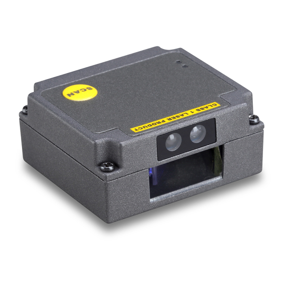
Page 13: Appearance Of The Scanner
2-3 Appearance of the scanner Beeper SCAN Infrared detecting Exit window Figure 2-2 Appearance of the scanner (with Zinc alloy case) Beeper SCAN Infrared detecting Exit window Figure 2-3 Appearance of the scanner (with ABS case) -
Page 14: Scan Angle
2-4 Scan angle Figure 2-4 Scan angle Note: The scanner’s sealing condition can meet its own protection require. It’s not necessary to add extra sealing protection. -
Page 15: Parameter Menus
3 Parameter menus When the scanner is scanning, ensure the scan line crosses every bar and space of the symbol. See Figure 3-1. √ × Figure 3-1 3-1 Example: Configure scanner by scanning configuration barcodes Throughout the programming barcode menus, the factory default settings are indicated with asterisks (*). - Page 16 SETUP barcode Single-scan barcode SETUP Alpha. Option barcode Option Single-scan setting entry None RTS/CTS Flow control (Host idle: Low RTS) RTS/CTS (Host idle: High RTS) ACK/NAK 1200 2400 Baud rate 4800 9600 19200 57600 115200 Alphanumeric entries Option barcode END barcode Figure 3-2 Set Flow control to be none...
-
Page 17: Interface
3-2 RS-232 interface Flow control: None-The communication only uses TXD and RXD signals without any hardware or software handshaking protocol. RTS/CTS-If the scanner wants to send the barcode data to host computer, it will issue the RTS signal first, wait for the CTS signal from the host computer, and then perform the normal data communication. - Page 18 SETUP Multiple-scan setting Single-scan setting Option barcode Option Alpha. entry None RTS/CTS Flow control (Host idle: Low RTS) RTS/CTS (Host idle: High RTS) ACK/NAK 0 ms 5 ms 10 ms Inter-character delay 20 ms 40 ms 80 ms 00-99 Response delay 00-99 (100 ms) 1200 Baud rate...
- Page 19 SETUP Multiple-scan setting Single-scan setting Option barcode Option Alpha. entry 19200 38400 57600 115200 None Parity Even 8 bits Data bit 7 bits 1 bits Stop bit 2 bits 00-99 Host-character delay 00-99(1ms) Disable Data package Enable...
-
Page 20: Usb Interface
3-3 USB interface USB device type: HID keyboard– By setting, the scanner is used as a USB HID keyboard emulation device. USB virtual COM– By setting, the scanner emulate a regular RS232-based COM port. If a Microsoft Windows PC is connected to the scanner, a driver is required to install on the connected PC. The driver will use the next available COM Port number. - Page 21 SETUP Multiple-scan setting Single-scan setting Option barcode Option Alpha. entry HID keyboard HID keyboard for Apple Mac USB device type USB virtual COM Simple COM Port Emulation Turkish F Turkish Q French Italian Spanish Keyboard layout Slovak Denmark Japanese German Belgian Russian 0 ms...
- Page 22 SETUP Multiple-scan setting Single-scan setting Option barcode Option Alpha. entry 20 ms 40 ms 60 ms Alphabetic key Numeric key Numeric keypad Alt+ keypad...
-
Page 23: Scan Mode & Some Global Settings
3-4 Scan mode & some global settings Scan mode: Good-read off-The trigger button must be pressed once to activate scanning. The light source of scanner stops scanning when there is a successful reading or no code is decoded after the Stand-by duration elapsed. - Page 24 otherwise the labels of the symbol will not be readable. In particular, the same value can be set for both minimum and maximum reading length to force the fixed length barcode decoded. Notes: 1. Please set the max./min. length for individual barcode in later sections, if special demand is requested.
- Page 25 SETUP Multiple-scan setting Single-scan setting Option barcode Option Alpha. entry Good-read off Momentary Alternate continue Scanning mode Continue Timeout off Auto-detection Good-read identification 01-99 Standby duration 01-99 (second) 00-FF Same barcode delay time 00-FF (50 second) 00-09 Double confirm 00-09 (00:no) 04-99 Global max.
- Page 26 SETUP Multiple-scan setting Single-scan setting Option barcode Option Alpha. entry Disable Element amendment Enable None Character output restraint Printable character only Alphanumeric character only Disable Decoder optimization Enable Data output delay in 00-FF 00-FF (100 ms) continue-scan mode (Never) 10 second 3 min 15 min Enter sleeping-mode delay...
-
Page 27: Indication
3-5 Indication Power on alert: After power-on the scanner will generate an alert signal to indicate a successful self-test. Beeper indication: After each successful reading, the scanner will beep to indicate a good barcode reading, and its beep tone duration is adjustable. Beep tone duration: This parameter can be adjusted for a good reading upon favorite usage. -
Page 28: Upc-A
3-6 UPC-A Read: Format System character Data digits (10 digits) Check digit Check digit verification: The check digit verification is optional. Check digit trans.: By setting Enable, check digit will be transmitted. Code ID setting: Code ID is a one-or-two-character string used to represent the symbol upon a succeeding reading. - Page 29 SETUP Multiple-scan setting Single-scan setting Option barcode Option Alpha. entry Disable Read Enable Disable Check digit verification Enable Disable Check digit trans. Enable 00-FF Code ID setting 00-FF (ASCII) <A>* 00-66 Insert group selection 00-66 None 2 digits Supplement digits 5 digits 2 or 5 digits None...
-
Page 30: Upc-E
3-7 UPC-E Read: Format System character “0” Data digits (6 digits) Check digits Check digit verification: The check digit verification is optional. Check digit trans.: By setting Enable, check digit will be transmitted. 3-6 UPC-A Code ID setting: Refer to Code ID setting of “ ”. - Page 31 SETUP Multiple-scan setting Single-scan setting Option barcode Option Alpha. entry Disable Read Enable Disable Check digit verification Enable Disable Check digit trans. Enable 00-FF Code ID setting 00-FF (ASCII) <D>* 00-66 Insert group selection 00-66 None 2 digits Supplement digits 5 digits 2 or 5 digits None...
-
Page 32: Upc-E1
3-8 UPC-E1 Read: Format System character “1” Data digits (6 digits) Check digits Check digit verification: The check digit verification is optional. Check digit trans.: By setting Enable, check digit will be transmitted. 3-6 UPC-A Code ID setting: Refer to Code ID setting of “ ”. - Page 33 SETUP Multiple-scan setting Single-scan setting Option barcode Option Alpha. entry Disable Read Enable Disable Check digit verification Enable Disable Check digit trans. Enable 00-FF Code ID setting 00-FF (ASCII) <D>* 00-66 Insert group selection 00-66 None 2 digits Supplement digits 5 digits 2 or 5 digits None...
-
Page 34: Isbn/Issn)
3-9 EAN-13 (ISBN/ISSN) Read: Format Data digits (12 digits) Check digit Check digit verification: The check digit verification is optional . Check digit transmission: By setting Enable, check digit will be transmitted. 3-6 UPC-A EAN-13 code ID setting: Refer to Code ID setting of “ ”. - Page 35 SETUP Multiple-scan setting Single-scan setting Option barcode Option Alpha. entry 00-66 Insert group selection 00-66 None 2 digits Supplement digits 5 digits 2 or 5 digits Disable ISBN/ISSN conversion Enable 00-FF ISBN/ISSN code ID setting 00-FF (ASCII) <B>*...
-
Page 36: Ean-8
3-10 EAN-8 Read: Format Data digits (7 digits) Check digit Check digit verification: The check digit verification is optional. Check digit trans.: By setting Enable, check digit will be transmitted. 3-6 UPC-A Code ID setting: Refer to Code ID setting of “ ”. - Page 37 SETUP Multiple-scan setting Single-scan setting Option barcode Option Alpha. entry Disable Read Enable Disable Check digit verification Enable Disable Check digit trans. Enable 00-FF Code ID setting 00-FF (ASCII) <C>* 00-66 Insert group selection 00-66 None 2 digits Supplement digits 5 digits 2 or 5 digits None...
-
Page 38: Code 39 (Code 32, Trioptic Code 39)
3-11 Code 39 (Code 32, Trioptic Code 39) Read: Format Start character(*) Data digits (variable) Check digit (optional) End character (*) Check digit verification: The check digit verification is optional. Check digit transmission: By setting Enable, check digit will be transmitted. Max./Min. - Page 39 SETUP Multiple-scan setting Single-scan setting Option barcode Option Alpha. entry Disable Read Enable Disable Check digit verification Enable Disable Check digit transmission Enable 00-99 Max. code length 00-99 00-99 Min. code length 00-99 00-FF Code ID setting 00-FF (ASCII) <M>* 00-66 Insert group selection 00-66...
- Page 40 SETUP Multiple-scan setting Single-scan setting Option barcode Option Alpha. entry Disable Convert Code 39 to Code 32 Enable Disable Code 32 Prefix “A” transmission Enable Disable Trioptic Code 39 read Enable Disable Trioptic Code 39 Start/End transmission Enable Note 1: If Trioptic Code 39 is set Enable, Code 39 is forced Enable. Note 2: If Code 39 is set Disable, Trioptic Code 39 is forced Disable.
-
Page 41: Interleaved 2 Of 5
3-12 Interleaved 2 of 5 Read: Format Data digits (Variable) Check digit (optional) Check digit verification: The check digit verification is optional. Check digit transmission: By setting Enable, check digit will be transmitted. 3-11 Code 39 (Code 32, Trioptic Code 39) Max./Min. - Page 42 SETUP Multiple-scan setting Single-scan setting Option barcode Option Alpha. entry Disable Read Enable Disable Check digit verification OPCC Disable Check digit transmission Enable 00-99 Max. code length 00-99 00-99 Min. code length 00-99 00-FF Code ID setting 00-FF (ASCII) <I>* 00-66 Insert group selection 00-66...
-
Page 43: Industrial 2 Of 5
3-13 Industrial 2 of 5 Read: Format Data digits (variable) Check digit transmission: By setting Enable, check digit will be transmitted. 3-11 Code 39 (Code 32, Trioptic Code 39) Max./Min. code length: Refer to Max./Min. code length of “ ”. 3-6 UPC-A Code ID setting: Refer to Code ID setting of “... -
Page 44: Matrix 2 Of 5
3-14 Matrix 2 of 5 Read: Format Data digits (variable) Check digit (optional) Check digit verification: The check digit verification is optional. Check digit transmission: By setting Enable, check digit will be transmitted. 3-11 Code 39 (Code 32, Trioptic Code 39) Max./Min. - Page 45 SETUP Multiple-scan setting Single-scan setting Option barcode Option Alpha. entry Disable Read Enable Disable Check digit verification Enable Disable Check digit transmission Enable 00-99 Max. code length 00-99 00-99 Min. code length 00-99 00-FF Code ID setting 00-FF (ASCII) <X>* 00-44 Insert group selection 00-44...
-
Page 46: Codabar
3-15 Codabar Read: Format Start character Data digits (variable) Check digit (optional) End character Check digit verification: The check digit verification is optional. Check digit transmission: By setting Enable, check digit will be transmitted. 3-11 Code 39 (Code 32, Trioptic Code 39) Max./Min. - Page 47 SETUP Multiple-scan setting Single-scan setting Option barcode Option Alpha. entry 00-FF Code ID setting 00-FF (ASCII) <N>* 00-66 Insert group selection 00-66 ABCD/ABCD abcd/abcd Start/End type ABCD/TN*E abcd/tn*e Disable Start/End transmission Enable Disable Start/End character equality Enable...
-
Page 48: Code 128
3-16 Code 128 Read: Format Data digits (variable) Check digit (optional) Check digit verification: The check digit verification is optional. Check digit transmission: By setting Enable, check digit will be transmitted. 3-11 Code 39 (Code 32, Trioptic Code 39) Max./Min. code length: Refer to Max./Min. code length of “ ”. - Page 49 SETUP Multiple-scan setting Single-scan setting Option barcode Option Alpha. entry Disable Read Enable Disable Check digit verification Enable Disable Check digit transmission Reserved 00-99 Max. code length 00-99 00-99 Min. code length 00-99 00-FF Code ID setting 00-FF (ASCII) <K>* 00-66 Insert group selection 00-66...
-
Page 50: Ucc/Ean 128
3-17 UCC/EAN 128 Read: Format Data digits (variable) Check digit (optional) Check digit verification: The check digit verification is optional. Check digit transmission: By setting Enable, check digit will be transmitted. 3-11 Code 39 (Code 32, Trioptic Code 39) Max. /Min. code length: Refer to Max./Min. code length of “ ”. - Page 51 SETUP Multiple-scan setting Single-scan setting Option barcode Option Alpha. entry Disable Read Enable Disable Check digit verification Enable Disable Check digit transmission Reserved 00-99 Max. code length 00-99 00-99 Min. code length 00-99 00-FF Code ID setting 00-FF (ASCII) <K>* 00-66 Insert group selection 00-66...
-
Page 52: Isbt 128
3-18 ISBT 128 Read: Format “=” or “&” Data digits (variable) Check digit (optional) Check digit verification: The check digit verification is optional. Check digit transmission: By setting Enable, check digit will be transmitted. 3-11 Code 39 (Code 32, Trioptic Code 39) Max./Min. - Page 53 SETUP Multiple-scan setting Single-scan setting Option barcode Option Alpha. entry Disable Read Enable Disable Check digit verification Enable Disable Check digit transmission Reserved 00-99 Max. code length 00-99 00-99 Min. code length 00-99 00-FF Code ID setting 00- FF (ASCII) <K>* 00-66 Insert group selection...
-
Page 54: Code 93
3-19 Code 93 Read: Format Data digits (variable) 2 check digits (optional) Check digit verification: The check digit verification is optional. Check digit transmission: By setting Enable, check digit will be transmitted. 3-11 Code 39 (Code 32, Trioptic Code 39) Max./Min. - Page 55 SETUP Multiple-scan setting Single-scan setting Option barcode Option Alpha. entry Disable Read Enable Disable Check digit verification Enable Disable Check digit transmission Enable 00-99 Max. code length 00-99 00-99 Min. code length 00-99 00-FF Code ID setting 00-FF (ASCII) <L>* 00-66 Insert group selection 00-66...
-
Page 56: Code 11
3-20 Code 11 Read: Format Data digits (variable) Check digit 1 (optional ) Check digit 2 (optional) Check digit verification: The check digit verification is optional. Check digit transmission: By setting Enable, check digit 1 and check digit 2 will be transmitted upon the selected check digit verification method. - Page 57 SETUP Multiple-scan setting Single-scan setting Option barcode Option Alpha. entry Disable Read Enable Disable 1 digit Check digit verification Reserved Reserved Disable Check digit transmission Enable 00-99 Max. code length 00-99 00-99 Min. code length 00-99 00-FF Code ID setting 00-FF (ASCII) <V>*...
-
Page 58: Msi/Plessey
3-21 MSI/Plessey Read: Format Data digits (variable) Check digit 1 (optional) Check digit 2 (optional) Check digit verification: The MSI/Plessey has one or two optional check digits. There are three methods to verify check digits, i.e. Mod10, Mod10/10 and Mod 11/10. The check digit 1 and check digit 2 will be calculated as the sum module 10 or 11 of the data digits. - Page 59 SETUP Multiple-scan setting Single-scan setting Option barcode Option Alpha. entry Disable Read Enable Disable 1 digit (mod 10) Check digit verification Reserved Reserved Disable Check digit transmission Enable 00-99 Max. code length 00-99 00-99 Min. code length 00-99 00-FF Code ID setting 00-FF (ASCII) <O>*...
-
Page 60: Uk/Plessey
3-22 UK/Plessey Read: Format Data digits (variable) 2 check digits (optional) Check digit verification: The UK/Plessey has one or two optional check digits. The check digit 1 and check digit 2 will be calculated as the sum module 10 or 11 of the data digits. Check digit transmission: By setting Enable, check digit will be transmitted. - Page 61 SETUP Multiple-scan setting Single-scan setting Option barcode Option Alpha. entry Disable Read Enable Disable Check digit verification Enable Disable Check digit transmission Enable 00-99 Max. code length 00-99 00-99 Min. code length 00-99 00-FF Code ID setting 00-FF (ASCII) <U>* 00-66 Insert group selection 00-66...
-
Page 62: China Post
3-23 China Post Read: Format 11 Data digits 3-11 Code 39 (Code 32, Trioptic Code 39) Max. /Min. code length: Refer to Max./Min. code length of “ ”. The code length of China Post is 11. 3-6 UPC-A Code ID setting: Refer to Code ID setting of “ ”. -
Page 63: China Finance
3-24 China Finance Read: Format 10 Data digits 3-11 Code 39 (Code 32, Trioptic Code 39) Max./Min. code length: Refer to Max./Min. code length of “ ”. Check digit verification: The check digit verification is optional. Leading character 5/6/7/8/9 converted to A/B/C/D/E: By setting, leading character 5/6/7/8/9 can be converted to A/B/C/D/E. - Page 64 SETUP Multiple-scan setting Single-scan setting Option barcode Option Alpha. entry Disable Read Enable 00-99 Max. code length 00-99 00-99 Min. code length 00-99 Disable Check digit verification Reserved Disable Enable Only 5 converted to A Leading character 5/6/7/8/9 converted to A/B/C/D/E Only 6 converted to B Only 7 converted to C Only 8 converted to D...
- Page 65 SETUP Multiple-scan setting Single-scan setting Option barcode Option Alpha. entry Assigned to 8(D) Assigned to 9(E) Assigned to 1 Assigned to 2 Assigned to 3 Assigned to 4 00-FF Code ID setting 00-FF (ASCII) <Y>* 00-66 Insert group selection 00-66 Laser Light Direction Setting: By scanning the barcode above, the decoding direction of the scanner’s laser light is from left to right.
-
Page 66: Telepen
3-25 Telepen Read: Format Start character (_) Data digits (variable) Check digit End character (z) Check digit verification: The check digit verification is optional. Check digit transmission: By setting Enable, check digit will be transmitted. 3-11 Code 39 (Code 32, Trioptic Code 39) Max./Min. - Page 67 SETUP Multiple-scan setting Single-scan setting Option barcode Option Alpha. entry Disable Read Enable Disable Check digit verification Enable Disable Check digit transmission Enable 00-99 Max. code length 00-99 00-99 Min. code length 00-99 00-FF Code ID setting 00-FF 00-66 Insertion group selection 00-66 Alphanumeric Encode character set type...
-
Page 68: Gs1 Databar (Gs1 Databar Truncated)
3-26 GS1 DataBar (GS1 DataBar Truncated) GS1 DataBar Truncated is structured and encoded as the same as the standard GS1 DataBar format, except its height is reduced to a 13 modules minimum; while GS1 DataBar should have a height greater than or equal to 33 modules. -
Page 69: Gs1 Databar Limited
3-27 GS1 DataBar Limited Read: Format 16 Data digits 3-6 UPC-A Code ID setting: Refer to Code ID setting of “ ”. 3-6 UPC-A Insertion group selection: Refer to Insertion group selection of “ ”. 3-26 GS1 DataBar (GS1 DataBar Truncated) Conversion: Refer to Conversion of “... -
Page 70: Gs1 Databar Expanded
3-28 GS1 DataBar Expanded Read: Format Data characters (variable) 3-6 UPC-A Code ID setting: Refer to Code ID setting of “ ”. 3-6 UPC-A Insertion group selection: Refer to Insertion group selection of “ ”. Conversion: 3-31 String transmission UCC/EAN 128- Refer to Code ID transmission of “ ”, ]Cm will be identified as AIM ID. -
Page 71: G1-G6 & Fn1 Substitution String Setting
3-29 G1-G6 & FN1 substitution string setting Format of barcode data transmission Prefix Code name Preamble Code ID Code length Code data Code ID Postamble Suffix Suffix string setting: The <enter > key is represented in different ASCII when it is applied by different OS. For a Windows/DOS OS, <enter>... - Page 72 FN1 substitution string setting: The FN1 character (0x1D) in an UCC/EAN128 barcode, or a Code 128 barcode, or a GS1 DataBar barcode can be substituted with a defined string. Truncate leading G5 string setting: By setting, a defined leading character or string can be truncated. Also a single character can be un-defined.
- Page 73 SETUP Multiple-scan setting Single-scan setting Option barcode Option Alpha. entry 0-22 characters 00-FF Prefix string setting None 0-22 characters 00-FF Suffix string setting <ENTER> 0D0A* 0-22 characters 00-FF Preamble string setting None 0-22 characters 00-FF Postamble string setting None 0-22 characters 00-FF Insert G1 string setting None...
- Page 74 SETUP Multiple-scan setting Single-scan setting Option barcode Option Alpha. entry <0> Once Repeat of a G5 character setting Defined times 01-22 Un-defined times (All) A un-defined character Truncate ending G6 string setting 1-22 defined characters 01-7F <0> Once Repeat of a G6 character setting Defined times 01-22 Un-defined times (All)
-
Page 75: G1-G4 String Position & Code Id Position
3-30 G1-G4 string position & Code ID position Format of barcode data transmission Prefix Code name Preamble Code ID Code length Code data Code ID Postamble Suffix Insert G1/G2/G3/G4 string position: The scanner offers 4 positions to insert strings among the symbol. In case of the insertion position is greater than the length of the symbol, the insertion of string is not effective. -
Page 76: String Transmission
3-31 String transmission Format of barcode data transmission Prefix Code name Preamble Code ID Code length Code data Code ID Postamble Suffix Prefix transmission: By setting Enable, prefix will be appended before the data transmitted. Suffix transmission: By setting Enable, suffix will be appended after the data is transmitted. Code name transmission: By setting Enable, code name will be transmitted before code data. - Page 77 SETUP Multiple-scan setting Single-scan setting Option barcode Option Alpha. entry Disable Prefix transmission Enable Disable Suffix transmission Enable Disable Code name transmission Enable Disable Preamble transmission Enable Disable Postamble transmission Enable Disable Code ID transmission Proprietary ID AIM ID Disable Code length transmission Enable Disable...
- Page 78 SETUP Multiple-scan setting Single-scan setting Option barcode Option Alpha. entry Lower (whole string) Disable Keyboard wedge /USB FN1 substitution transmission RS-232 Keyboard wedge / USB / RS-232 All-non-printable-character string Disable transmission with string setting Enable Transmit the first N data characters only 01-99 01-99...
-
Page 79: Operate The Scanner By Command Via Uart Or Usb Virtual Uart
4 Operate the scanner by command via UART or USB virtual UART Note: 1- The information in this chapter is provided for the scanner with RS232 cable or USB cable. 2- If the scanner is with USB cable, the setting of USB device type must be set as “USB virtual COM”. 3-3 USB interface Please refer to chapter of “... -
Page 80: Command Data Packet Format
4-1 Command data packet format The general packet format is as following: Length Opcode Status Data Checksum Notice: Opcode is the abbreviation about Operation code. Table 4-2 lists the descriptions of fields that occur in all messages. This description is repeated for each opcode. -
Page 81: Cmd_Ack
4-2 CMD_ACK Description: Positive acknowledgment of received packet. Packet Format Length Opcode Status Checksum 0x59 0x03 (‘Y’) Field Descriptions Table 4-3 Field Descriptions Field name Format Size Description Length of message (not Length 1 byte Length of Field including checksum). Opcode 0x59 1 byte... - Page 82 section. If the scanner does not receive an ACK within this time period, it sends the previous message again. The scanner retries twice more (with the retransmit status bit set) before declaring a transmit error.
-
Page 83: Cmd_Nak
4-3 CMD_NAK Description: Negative acknowledgment of received packet Packet Format Length Opcode Status Cause Checksum 0x4E 0x04 (‘N’) Field Descriptions Table 4-4 Field Descriptions Field Name Format Size Description Length of message (not Length 1 Byte Length Field including checksum). Opcode 0x4E 1 Byte... - Page 84 and issues transmit error beep. When ACK/NAK handshaking is disabled, the CMD_NAK message will not be sent. It is not necessary to respond to a valid ACK or NAK message. For example: Length Opcode Status Cause Checksum 0x04 0x4E 0x00 0x40 (the parameter wishing to change is not existed) 0xFF 0x6E Table 4-5 describes NAK types supported by the scanner.
-
Page 85: Decode_Data
4-4 DECODE_DATA Description: Decode data in UART packet format Packet Format Length Opcode Status Decode Data Checksum 0x50 (‘P’) Field Descriptions Table 4-6 Field Descriptions Field Name Format Size Description Length of message (not Length 1 Byte Length Field including checksum). Opcode 0x50 1 Byte... -
Page 86: Request_Revision
4-5 REQUEST_REVISION Description: Request the software revision string from the engine Packet Format Length Opcode Status Checksum 0x56 0x03 (‘V’) Field Descriptions Table 4-7 Field Descriptions Field Name Format Size Description Length of message (not including Length 1 Byte Length Field checksum). -
Page 87: Reply_Revision
4-6 REPLY_REVISION Description: Reply to REQUEST_REVISION command with software revision string Packet Format Length Opcode Status Revision Checksum 0x52 (‘R’) Field Descriptions Table 4-8 Field Descriptions Field Name Format Size Description Length of message (not including Length 1 Byte Length Field checksum). -
Page 88: Start_Decode
4-7 START_DECODE Description: Ask the scanner to attempt to decode a barcode Packet Format Length Opcode Status Checksum 0x53 0x03 (‘S’) Field Descriptions Table 4-9 Field Descriptions Field Name Format Size Description Length of message (not including Length 1 Byte Length Field checksum). -
Page 89: Stop_Decode
4-8 STOP_DECODE Description: Ask scanner to abort a decode attempt Packet Format Length Opcode Status Checksum 0x45 0x04 (‘E’) Field Descriptions Table 4-10 Field Descriptions Field Name Format Size Description Length of message (not including Length 1 Byte Length Field checksum). -
Page 90: Param_Defaults
1: Command is from the host. Bit 7: Command source 0: Command is from the scanner All unused bits must be set to 0. 0-255. 0: Default setting 0 (Mindeo standard) Setting type Default setting type 1 Byte 1: Default setting 1... -
Page 91: Param_Request
4-10 PARAM_REQUEST Description: Request values of selected parameters Packet Format Length Opcode Status Checksum Option code 0x3F (‘?’) Field Descriptions Table 4-12 Field Descriptions Field Name Format Size Description Length of message (not including Length 1 Byte Length Field checksum). Opcode 0x3F 1 Byte... - Page 92 scanner responses NAK. The scanner’s response to this command is PARAM_SEND, not ACK. Depending on the time-out setting, and the number of parameters requested, this reply may fall outside the programmable Host Serial Response Time-out. If this occurs, this is not a time-out error. To compensate, increase the time-out. Scanner Requirements When the scanner receives this message, it processes the information by formatting a PARAM_SEND message containing all requested parameters supported and their values.
-
Page 93: Param_Send
4-11 PARAM_SEND Description: the command performs two optional operations: 1) The scanner respond to a PARAM_REQUEST. 2)The host demand scanner to change particular parameter values. Packet Format Data Parameter Length Opcode Status Option code … Checksum type value 0x23 (‘#’) Field Descriptions Table 4-13 Field Descriptions Field Name... - Page 94 Field Name Format Size Description ending with ‘\0’,1 to 23 bytes. Parameter Variable 1 to 23 bytes Value Next parameter setting(option code,data … Variable type,parameter value)…. 2's complement sum of Checksum message contents 2 Bytes Checksum of message. excluding checksum. This message is sent by the scanner in response to the PARAM_REQUEST message, or by the host to change the scanner’s parameter values.
- Page 95 is sent for any unsupported parameter. If none of the requested values is supported, the scanner responds to the host with NAK. When the scanner sends PARAM_SEND message, the Change Type bit (bit 6 of Status byte) can be ignored. PARAM_REQUEST Host Engine...
-
Page 96: Upgrade
4-12 UPGRADE Description: the command demands the scanner to upgrade its firmware. Packet Format Data Length Opcode Status Checksum 0x55 0x07 (‘U’) Field Descriptions Table 4-14 Field Descriptions Field Name Format Size Description Length of message (not Length 1 Byte Length Field including checksum). -
Page 97: Restart
4-13 RESTART Description: the command demands the scanner to restart. Packet Format Length Opcode Status Checksum 0x5E 0x03 (‘^’) Field Descriptions Table 4-15 Field Descriptions Field Name Format Size Description Length of message (not Length 1 Byte Length Field including checksum). Opcode 0x5E 1 Byte... -
Page 98: Good_Read_Start
4-14 GOOD_READ_START Description: the command demands the scanner to start to decode to identify whether the barcode is readable or not. Packet Format <SYN> <T> <CR> 0x16 0x54 0x0D Host Requirements The host sends GOOD_READ_START to the scanner to identify the barcode is readable or not. Scanner Requirements If ACK/NAK handshaking is enabled, the scanner responds with ACK or NAK and then start to decode, when it receives the GOOD_READ_START command. -
Page 99: Good_Read_Stop
4-15 GOOD_READ_STOP Description: the command demands the scanner to stop executing GOOD_READ_START command. Packet Format <SYN> <U> <CR> 0x16 0x55 0x0D Host Requirements The host sends GOOD_READ_STOP command to the scanner to stop executing GOOD_READ_START command. Scanner Requirements If ACK/NAK handshaking is enabled, the scanner responds with ACK or NAK and then stops decoding, when it receives the GOOD_READ_STOP command. -
Page 100: The Control Of Timing Conflict
4-16 The control of timing conflict If the scanner has started the data transmission, while the host sends commands to the scanner, once the scanner receives complete command, it stops its data transmission to respond the host command, and then restart the terminated data transmission, due to the data transmitted in packet format, the host can accurately separate from the received data: 1) response information. -
Page 101: Troubleshooting
5 Troubleshooting Nothing happens when you follow the operating instruction, or the Problem scanner displays erratic behavior. 1) No power to the scanner. Check the system power. Ensure the Possible causes and power supply is connected. possible solution 2) The cable connection is incorrect. Connect the cable again. Problem Scanned data is incorrectly displayed on the host. -
Page 102: Maintenance
6 Maintenance Cleaning the exit window is the only maintenance required. A dirty window may affect scanning accuracy. Do not allow any abrasive material to touch the window. Remove any dirt particles with a damp cloth. Wipe the window using a tissue moistened with water. Do not spray water or other cleaning liquids directly into the window. -
Page 103: Barcode Representing Non-Printable Character
7 Barcode representing non-printable character Notes to make the following barcode: 1. According to different barcode printing software, the method of printing following barcode is different. 2. If using CODESOFT software, firstly read the information through “Help→Index→Code128→Special input syntax”. Also refer to ASCII table. For example, if we wish to make “F1” barcode, select “code128”, then select “CODE A”... -
Page 104: Ascii Table
8 ASCII Table RS-232 Null Down Left Right PgUp PgDn Home Enter Insert Ctrl+ Delete Alt+ Note: the second and third columns are just used for USB interface in above table. “ & ‘ ( ) : < > Example:ASCII “A” = “41”。... -
Page 105: Test Symbols
9 Test symbols UPC-A UPC-E UPC-E1 EAN-13 ISBN/ISSN EAN-8 Code 39 Code 32 A908765439 Trioptic Code 39 (Default setting: Disable) Interleaved 2 of 5 Industrial 2 of 5 (Default setting: Disable) Matrix 2 of 5 Codabar... - Page 106 Test chart (continue) Code 128 UCC/EAN 128 ISBT 128 Code 93 Code 11 (Default setting: Disable) MSI/Plessey (Default setting: Disable) UK/Plessey China Post Telepen GS1 DataBar (GS1 DataBar Truncated) GS1 DataBar Limited GS1 DataBar Expanded...
-
Page 107: Return Default Parameters & Firmware Version
10 Return default parameters & firmware version WARNING: Default value initialization If you wish to return the scanner to all the factory default settings, scan the barcode above. Note: the default setting barcode has no influence on the scanning mode setting. Firmware version list If you wish to display the firmware version, scan the barcode above. -
Page 108: Configuration Alphanumeric Entry Barcode
11 Configuration alphanumeric entry barcode To finish parameter setting, please scan the bar code below.
Need help?
Do you have a question about the ES4200 and is the answer not in the manual?
Questions and answers