Advertisement
SY3000-TFS01EN
ORIGINAL INSTRUCTIONS
Instruction Manual
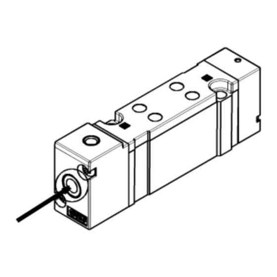
5 Port Air Operated Valve
Series SYA3000/5000/7000
The intended use of this product is to control the movement of an
actuator.
Note 1)
Validated according to ISO 13849
, see section 2.
Note 1)
Not all variants of this product series are validated. Please
refer to "How to Order" section 5 for details.
Refer to product catalogues for additional information.
1 Safety Instructions
These safety instructions are intended to prevent hazardous situations
and/or equipment damage. These instructions indicate the level of
potential hazard with the labels of "Caution", "Warning" or "Danger".
They are all important notes for safety and must be followed in addition
*1)
to International Standards (ISO/IEC)
, and other safety regulations.
*1)
ISO 4414: Pneumatic fluid power - - General rules relating to
systems.
ISO 4413: Hydraulic fluid power - - General rules relating to
systems.
IEC 60204-1: Safety of machinery - -Electrical equipment of
machines. (Part 1: General requirements)
ISO 10218-1: Manipulating industrial robots -Safety.etc.
This manual contains essential information for the protection of users
and others from possible injury and/or equipment damage.
• Read this manual before using the product, to ensure correct
handling, and read the manuals of related apparatus before use.
• Keep this manual in a safe place for future reference.
• To ensure safety of personnel and equipment the safety instructions
in this manual must be observed, along with other relevant safety
practices.
Caution indicates a hazard with a low level of risk
Caution
which, if not avoided, could result in minor or
moderate injury.
Warning indicates a hazard with a medium level
Warning
of risk which, if not avoided, could result in death
or serious injury.
Danger indicates a hazard with a high level of risk
Danger
which, if not avoided, will result in death or serious
injury.
Warning
• The compatibility of the product is the responsibility of the
person who designs the equipment or decides its specifications.
Since the product specified here is used under various operating
conditions, its compatibility with specific equipment must be decided
by the person who designs the equipment or decides its
specifications based on necessary analysis and test results. The
expected performance and safety assurance of the equipment will be
the responsibility of the person who has determined its compatibility
with the product. This person should also continuously review all
specifications of the product referring to its latest catalogue
information, with a view to giving due consideration to any possibility
of equipment failure when configuring the equipment.
1 Safety Instructions - continued
• Only personnel with appropriate training should operate
machinery and equipment.
The product specified here may become unsafe if handled
incorrectly.
The assembly, operation and maintenance of machines or equipment
including our products must be performed by an operator who is
appropriately trained and experienced.
• Do
not
service
or
attempt
to
remove
product
machinery/equipment until safety is confirmed.
1) The inspection and maintenance of machinery/equipment should
only be performed after measures to prevent falling or runaway of the
driven objects have been confirmed.
2) When the product is to be removed, confirm that the safety
measures as mentioned above are implemented and the power from
any appropriate source is cut, and read and understand the specific
product precautions of all relevant products carefully.
3) Before machinery/equipment is restarted, take measures to
prevent unexpected operation and malfunction.
• Contact SMC beforehand and take special consideration of
safety measures if the product is to be used in any of the
following conditions.
1) Conditions and environments outside of the given specifications, or
use outdoors or in a place exposed to direct sunlight.
2) Installation on equipment in conjunction with atomic energy,
railways, air navigation, space, shipping, vehicles, military, medical
treatment, combustions and recreation, or equipment in contact with
food and beverages, emergency stop circuits, clutch and brake
circuits in press applications, safety equipment or other applications
unsuitable for the standard specification described in the product
catalogue.
3) An application which could have negative effects on people,
property, or animals requiring special safety analysis outside the
scope of ISO 13849 described in this document.
4) Use in an interlock circuit, which requires the provision of double
interlock for possible failure by using a mechanical protective
function, and periodical checks to confirm proper operation.
• Always ensure compliance with relevant safety laws and
standards.
All electrical work must be carried out in a safe manner by a qualified
person in compliance with applicable national regulations.
Caution
• The product is provided for use in manufacturing industries.
The product herein described is basically provided for peaceful use in
manufacturing industries.
If considering using the product in other industries, consult SMC
beforehand and exchange specifications or a contract if necessary.
If anything is unclear, contact your nearest sales branch.
2 Specifications
Fluid
Air
2 position single
0.15 to 0.7
Operating
pressure range
2 position double
-100 kPa to 0.7
[MPa]
3 position
-100 kPa to 0.7
(0.7 x P + 0.1) to 0.7 P:
2 position single
Pilot pressure
Operating pressure range
Note 1)
range
2 position double
0.1 to 0.7
[MPa]
3 position
0.2 to 0.7
Ambient and fluid temperature [° C]
-10 to +60 (no freezing)
Manual override (Manual operation)
Non-locking push type
Maximum
2 position single
5
operating
2 position double
5
frequency (Hz)
3 position
3
Minimum operating frequency
1 cycle/30days
Lubrication
Not required (refer to 3.4)
Mounting orientation
Unrestricted
Note 2)
2
Impact/Vibration resistance
[m/s
]
150 / 30
Air quality
5µm filtration or smaller
2 Specifications – continued
Flow
Complies with the basic and
Note 3)
Standards
well-tried safety principles of
ISO 13849-2:2012
2 Position single
Note 4)
B
10
3 Position
2 Position single
Note 4)
B
10D
and
3 Position
Table 1
Notes:
Note 1) In case of single type, be certain that pressure within operating
pressure range be supplied to supply port, because return
pressure is introduced from supply port {1(P)} for activation.
Note 2) Impact resistance: No malfunction resulted from the impact test
using a drop impact tester. The test was performed on the axis
and right angle directions of the main valve and armature, when
pilot signal is ON and OFF. (Value in the initial state)
Vibration resistance: No malfunction occurred in one sweep test
between 45 and 2000 Hz. Test was performed to axis and right
angle directions of the main valve and armature when pilot
signal is ON and OFF. (Value in the initial state)
Note 3) For validated variants refer to section 5 "How to Order".
Note 4) Under SMC test conditions. The B
figure is estimated from
10
SMC life tests. The B
figure is derived from B
10D
assumption in EN ISO 13849-1:2015 Annex C. Contact SMC for
details.
2.1 Flow characteristics
1 → 4/2 (P → A/B)
Model
3
C [dm
/(s·bar)]
b
SYA3000
1.0
0.30
SYA5000
2.4
0.41
SYA7000
4.9
0.29
Table 2
4/2 → 5/3 (A/B → EA/EB)
Model
3
C [dm
/(s·bar)]
b
SYA3000
1.1
0.30
SYA5000
2.8
0.29
SYA7000
4.5
0.27
Table 3
Note: The values given in Table 2 and Table 3 vary depending on the
different types of actuation and selected port size. Refer to the
catalogue for full details.
2.2 Pilot Pressure Range (Single pilot)
Pilot pressure
range
Operating pressure [MPa]
Figure 1
2 Specifications – continued
Refer to 2.1
2.3 Symbols
2 position single
47 million cycles
27 million cycles
94 million cycles
54 million cycles
3 position closed
3 position exhaust
center
Note) Refer to section "8 Limitations of Use" for valves with air return or
combined air/spring return spool.
2.4 Manual Override Operation
• Non-locking push type [Standard]
using the
10
Press in the direction of the arrow.
Cv
0.24
0.64
1.2
Cv
Special products might have specifications different from those shown
0.26
in this section. Contact SMC for specific drawings. These drawings will
0.66
give the appropriate specification details and compliance with the safety
1.1
principles of ISO 13849, if applicable.
3 Installation
3.1 Installation
• Do not install the product unless the safety instructions have been
read and understood.
• If air leakage increases or equipment does not operate properly,
stop operation.
Check mounting conditions when the air supply is connected. Initial
function and leakage tests should be performed after installation.
• Ensure sufficient space for maintenance activities.
When installing the products, allow access for maintenance.
• Operation in a vacuum condition
When a valve is used for switching a vacuum, take measures to
install a suction filter or similar to prevent external dust or other
foreign matter from entering inside the valve.
In addition, at the time of vacuum adsorption, be sure to vacuum at
all times. Failure to do so may result in foreign matter sticking to the
adsorption pad, or air leakage causing the workpiece to drop.
• Regarding a vacuum switch valve and a vacuum release valve
If a non-vacuum valve is installed in the middle of piping system
having a vacuum, the vacuum condition will not be maintained. Use a
valve designed for use under vacuum condition.
3.2 Environment
• Do not use in an environment where corrosive gases, chemicals, salt
water or steam are present.
• Do not use in an explosive atmosphere.
2 position double
3 position pressure
center
center
Figure 2
Warning
Figure 3
Caution
Warning
Warning
Page 1 of 3
Advertisement
Table of Contents

Subscribe to Our Youtube Channel
Related Manuals for SMC Networks SYA5000 Series


Summary of Contents for SMC Networks SYA5000 Series
- Page 1 SY3000-TFS01EN 1 Safety Instructions - continued 2 Specifications – continued 2 Specifications – continued ORIGINAL INSTRUCTIONS • Only personnel with appropriate training should operate Flow Refer to 2.1 2.3 Symbols machinery and equipment. Complies with the basic and 2 position single 2 position double Note 3) The product specified here may become unsafe if handled...
- Page 2 SY3000-TFS01EN 3 Installation – continued 3 Installation – continued 4 Settings – continued • About using the 2 position double type • Do not expose to direct sunlight. Use a suitable protective cover. Nylon tubing within ±0.1 mm When using the 2 position double type for the first time, actuators •...
- Page 3 SY3000-TFS01EN 6 Outline Dimensions (mm) 8 Limitations of Use – continued 9 Contacts Refer to the catalogue. Caution • SMC products are not intended for use as instruments for legal SMC Pneumatik GmbH,Girakstrasse 8, AT-2100 AUSTRIA 7 Maintenance Korneuburg, Austria metrology.
Need help?
Do you have a question about the SYA5000 Series and is the answer not in the manual?
Questions and answers