Table of Contents
Advertisement
Quick Links
SY3000-TFS01EN-A
ORIGINAL INSTRUCTIONS
Instruction Manual
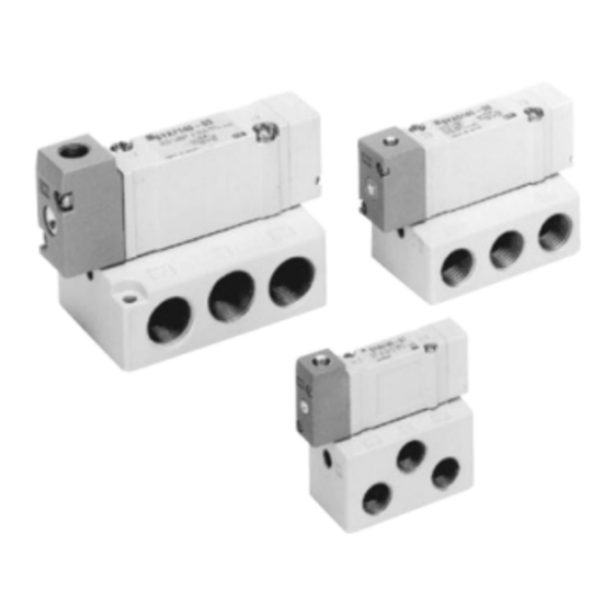
SYA3000/5000/7000
5 Port Air Operated Valve
The intended use of this product is to control the movement of an
actuator.
1 Safety Instructions
These safety instructions are intended to prevent hazardous situations
and/or equipment damage. These instructions indicate the level of
potential hazard with the labels of "Caution," "Warning" or "Danger."
They are all important notes for safety and must be followed in addition
*1)
to International Standards (ISO/IEC)
, and other safety regulations.
*1)
ISO 4414: Pneumatic fluid power - General rules relating to systems.
ISO 4413: Hydraulic fluid power - General rules relating to systems.
IEC 60204-1: Safety of machinery - Electrical equipment of machines.
(Part 1: General requirements)
ISO 10218-1: Manipulating industrial robots -Safety. etc.
• Refer to product catalogue, Operation Manual and Handling
Precautions for SMC Products for additional information.
• Keep this manual in a safe place for future reference.
Caution indicates a hazard with a low level of risk which, if
Caution
not avoided, could result in minor or moderate injury.
Warning indicates a hazard with a medium level of risk
Warning
which, if not avoided, could result in death or serious injury.
Danger indicates a hazard with a high level of risk which, if
Danger
not avoided, will result in death or serious injury.
Warning
• Always ensure compliance with relevant safety laws and
standards.
• All work must be carried out in a safe manner by a qualified person in
compliance with applicable national regulations.
2 Specifications
2.1
Specifications
Fluid
Air
2 position single
0.15 to 0.7
Operating
pressure range
2 position double
-100 kPa to 0.7
[MPa]
3 position
-100 kPa to 0.7
(0.7 x P + 0.1) to 0.7 P:
Pilot pressure
2 position single
Operating pressure range
range
Note 1)
2 position double
0.1 to 0.7
[MPa]
3 position
0.2 to 0.7
Ambient and fluid temperature [°C]
-10 to +60 (no freezing)
Manual override (Manual operation)
Non-locking push type
Maximum
2 position single
5
operating
2 position double
5
frequency (Hz)
3 position
3
Minimum operating frequency
1 cycle / 30days
Lubrication
Not required (refer to 3.4)
Mounting orientation
Unrestricted
Note 2)
2
Impact/Vibration resistance
[m/s
]
150 / 30
Flow characteristics
Refer to catalogue
Table 1.
2 Specifications - continued
Notes:
Note 1)
In case of single type, be certain that pressure within operating
pressure range is supplied to the supply port, because return pressure is
introduced from supply port {1(P)} for activation.
Note 2) Impact resistance: No malfunction resulted from the impact test
using a drop impact tester. The test was performed on the axis
and right angle directions of the main valve, when pilot signal is
ON and OFF. (Values quoted are for a new valve)
Vibration resistance: No malfunction occurred in one sweep test
between 45 and 2000 Hz. Test was performed to axis and right
angle directions of the main valve when pilot signal is ON and
OFF. (Values quoted are for a new valve)
2.2
Pilot Pressure Range (Single pilot)
Pilot pressure
range
Operating pressure [MPa]
Figure 1
2.3
Symbols
2 position single
2 position double
3 position closed
3 position pressure
3 position exhaust
centre
centre
centre
Figure 2
Note) Refer to section "7.9 Limitations of Use" for valves with air return
spool.
2.4
Manual Override Operation
Warning
• Non-locking push type [Standard]
Press in the direction of the arrow.
Figure 3
Warning
Special products might have specifications different from those shown in
this section. Contact SMC for specific drawings.
3 Installation
3.1
Installation
Warning
• Do not install the product unless the safety instructions have been read
and understood.
• If air leakage increases or equipment does not operate properly,
stop operation.
Check mounting conditions when the air supply is connected. Initial
function and leakage tests should be performed after installation.
• Ensure sufficient space for maintenance activities.
When installing the products, allow access for maintenance.
• Operation in a vacuum condition
When a valve is used for switching a vacuum, take measures to install
a suction filter or similar to prevent external dust or other foreign matter
from entering inside the valve.
• About ventilation
When it is used inside a sealed control panel, etc., provide ventilation
to prevent a pressure increase caused by exhausted air inside the
control panel or temperature rise caused by the any heat generated.
3.2
Environment
Warning
• Do not use in an environment where corrosive gases, chemicals, salt
water or steam are present.
• Do not use in an explosive atmosphere.
• Do not expose to direct sunlight. Use a suitable protective cover.
• Do not install in a location subject to vibration or impact in excess of
the product's specifications.
• Do not mount in a location exposed to radiant heat that would result in
temperatures in excess of the product's specifications.
3.3
Piping
Caution
• Before connecting piping make sure to clean up chips, cutting oil, dust
etc.
• When installing piping or fittings, ensure sealant material does not
enter inside the port. When using seal tape, leave 1 thread exposed
on the end of the pipe/fitting.
• Tighten fittings to the specified tightening torque.
Connection thread
Tightening torque [N m]
M5
1 to 1.5
1/8"
3 to 5
1/4"
8 to 12
3/8"
15 to 20
Table 2.
• Closed centre valves
When using closed centre type valves, check carefully to be sure there
are no air leaks from the piping between the valves and cylinders.
3.4
Lubrication
Caution
• SMC products have been lubricated for life at manufacture, and do not
require lubrication in service.
• If a lubricant is used in the system, refer to catalogue for details.
3.5
Air supply
Warning
Use clean air
If the compressed air supply includes chemicals, synthetic materials
(including organic solvents), salinity, corrosive gas etc., it can lead to
damage or malfunction.
Caution
Install an air filter
Install an air filter upstream of the valve. Select an air filter with a filtration
size of 5µm or smaller.
3.6
One-touch Fittings
3.6.1 Tube attachment and detachment
Caution
Refer to the Specific Precautions in the catalogue.
3.7
Precautions on other tubing brands
Caution
• When using non-SMC brand tubes, refer to the Specific Precautions in
the catalogue.
3 Installation - continued
3.8
Manual override
Warning
Since connected equipment will operate when the manual override is
activated, confirm that conditions are safe prior to activation.
4 How to Order
4.1
Standard products
Refer to catalogue for 'How to order' information.
4.2
Special products
For special products (-X number) refer to product drawing for 'How to
order' details and specifications.
5 Outline Dimensions (mm)
Refer to
catalogue
for outline dimensions.
6 Maintenance
6.1
General Maintenance
Caution
• Not following proper maintenance procedures could cause the product
to malfunction and lead to equipment damage.
• If handled improperly, compressed air can be dangerous.
• Maintenance of pneumatic systems should be performed only by
qualified personnel.
• Before performing maintenance, turn off the power supply and be sure
to cut off the supply pressure. Confirm that the air is released to
atmosphere.
• After installation and maintenance, apply operating pressure and
power to the equipment and perform appropriate functional and
leakage tests to make sure the equipment is installed correctly.
• If any electrical connections are disturbed during maintenance, ensure
they are reconnected correctly and safety checks are carried out as
required to ensure continued compliance with applicable national
regulations.
• Do not make any modification to the product.
• Do not disassemble the product, unless required by installation or
maintenance instructions.
6.2
Low frequency operation
Valves should be switched at least once every 30 days to prevent
malfunction. (Use caution regarding the air supply.)
6.3
Drain flushing
Remove drainage from air filters regularly.
6.4
Release of residual pressure
Provide a residual pressure release function for maintenance purposes.
Especially in case of 3 position closed centre valve or perfect valve,
ensure the release of residual pressure between valve and cylinder.
7.1
Limited warranty and Disclaimer/Compliance Requirements
Refer to Handling Precautions for SMC Products.
Caution
7.2
Intermediate stopping
Refer to Precautions of 3/4/5 port Solenoid Valves.
7.3
Effect of back pressure when using a manifold
Use caution when valves are used on a manifold, as actuator malfunction
due to back-pressure may occur.
Special caution must be taken when using 3 position exhaust centre
valve or when driving a single acting cylinder. To prevent a malfunction,
implement counter measures such as using a single EXH spacer
assembly or an individual exhaust manifold.
7.4
Holding of pressure (including vacuum)
Since valves are subject to air leakage, they cannot be used for
applications such as holding pressure (including vacuum) in a pressure
vessel.
7.5
Vacuum absorption
Stopping of continuous vacuum absorption can result in leakage, a
workpiece dropping or problems from foreign matter sticking to the
vacuum pad.
Page 1 of 2
Advertisement
Table of Contents

Related Manuals for SMC Networks SYA3000


Summary of Contents for SMC Networks SYA3000
- Page 1 Note 2) Impact resistance: No malfunction resulted from the impact test • If air leakage increases or equipment does not operate properly, SYA3000/5000/7000 4 How to Order using a drop impact tester. The test was performed on the axis stop operation.
- Page 2 SY3000-TFS01EN-A 7 Limitations of Use - continued About using the 2 position double type When using the 2 position double type for the first time, actuators may travel in an unexpected direction depending on the switching position of a valve. Implement countermeasures not to incur any danger by the actuator’s operation.
Need help?
Do you have a question about the SYA3000 and is the answer not in the manual?
Questions and answers